Table of Contents
Advertisement
Advertisement
Table of Contents

Related Manuals for Browan BW1254


Summary of Contents for Browan BW1254
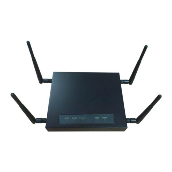
- Page 1 Dual Radio 802.11a/n+b/g/n Indoor Access Point BW1254 User’s Guide v1.0...
-
Page 2: Copyright
BROWAN reserves the right to change specifications without prior notice. While the information in this document has been compiled with great care, it may not be deemed an assurance of product characteristics. BROWAN shall be liable only to the degree specified in the terms of sale and delivery. - Page 3 BW1254 User Guide v1.0 Nov. 2013 Federal Communication Commission Interference Statement This equipment has been tested and found to comply with the limits for a Class B digital device, pursuant to Part 15 of the FCC Rules. These limits are designed to provide reasonable protection against harmful interference in a residential installation.
-
Page 4: Table Of Contents
BW1254 User Guide v1.0 Nov. 2013 Contents Copyright ............................. 1 Notice ..............................1 Trademarks ............................1 CONTENTS ............................3 ABOUT THIS GUIDE ..........................6 Purpose ............................... 6 Prerequisite Skills and Knowledge ...................... 6 ... - Page 5 BW1254 User Guide v1.0 Nov. 2013 Wireless | Neighbor List ......................... 58 Wireless | Priority 5G ........................59 User ..............................61 User | Users ........................... 61 User | Station Supervision ......................63 Services ............................. 64 ...
- Page 6 FAQ ..............................175 APPENDIX ............................176 A) Specification ..........................176 B) Factory Defaults for the BW1254 ....................177 Network Interface Configuration Settings ..................177 User Settings ..........................179 System Settings ........................... 179 ...
-
Page 7: About This Guide
Purpose This document provides information and procedures on hardware installation, setup, configuration, and management of the high performance Indoor Access Point BW1254. Prerequisite Skills and Knowledge To use this document effectively, you should have a working knowledge of Local Area Networking (LAN) concepts and wireless Internet access infrastructures. -
Page 8: Chapter 1 - Introduction
The BW1254 is fully compliant to 802.11a/b/g/n standard and provides the flexibility of different kinds of 802.11n, 802.11a, 802.11g or 802.11b clients access to the BW1254. With the high speed data rate(Max. 300Mbps) and security, feature rich software functionality, it provides the high performance wireless connection for the SMB, enterprise, and hotspot of public area. -
Page 9: Features Highlight
Power option includes an integrated IEEE 802.3at Power-over-Ethernet port enables effortless deployment in various environments. Easy and Secure Remote Management BW1254 supports secure remote management through HTTPS, CLISH, SNMP and TR-069(DMS) management. Secure management via HTTPs, CLISH, SNMP Support TR-069 protocol... -
Page 10: Chapter 2 - Installation
Nov. 2013 Chapter 2 - Installation This chapter provides installation instructions for the hardware and software components of the Access Point BW1254. It also includes the procedures for the following tasks: Hardware Introduction (LEDs, Connectors) Connecting the Access Point Software Installation... -
Page 11: Rear Panel
5 seconds to reset factory default configuration. Console For console connection(RJ-45 interface) LAN/PoE Connecting RJ-45 cable to Ethenet network and for PoE power supply. reserved table 2 – BW1254 connectors Bottom Cover The Bottom Cover of the BW1254 contains: Page 10 of 184... -
Page 12: Back Label
4. Rubber foot Wall mount hole 5. Wall mount hole Rubber foot Rubber foot Figure 4 –Bottom Cover of the BW1254 Back label The back label format and location as below. Figure 5 – back label Right side: Two RP-SMA type of antenna connectors for WLAN 1(2.4G) -
Page 13: Left Side
Connect DC 48V power supply to PoE injector DC jack. Step 3 Connect the Ethernet cable from the BW1254 to PoE injector “P+data” out port. Step 4 Connect Ethernet cable from PoE injector “data in” port to the computer or through LAN switch connect to your local network. -
Page 14: Access To Your Access Point
Configure your PC with a static IP address on the 192.168.2.x subnet with mask 255.255.255.0. Connect the BW1254 into the same physical network as your PC. Open the Web browser and type the default IP address of the BW1254: https://192.168.2.2/a.rg Step 2 Enter the BW1254 administrator login details to access the Web management. - Page 15 Figure 9 – Security alert Figure 10 – login page Step 3 After successful administrator log on you will see the main page of the BW1254 Web interface: Figure 11 – Web interface Management Menu Now you are enabled to perform your configuration.
-
Page 16: Chapter 3 - Reference Manual
Nov. 2013 Chapter 3 – Reference Manual----AP Mode This chapter describes the configuration of the BW1254 which works in AP mode using the Web Interface. The BW1254 Web Interface in AP mode is different from that in AP-Router mode. To change your BW1254 to AP-Router mode, please refer to System | System Mode . -
Page 17: Status
System Log – check the system log locally or specify address where to send system log file System Mode – specify whether the BW1254 works in AP mode or in AP router mode System Info – specify some device related information for BW1254 Configuration –... - Page 18 Free System Memory – indicate the memory currently available in the BW1254 Total System Memory – indicate the total memory in the BW1254 LAN Mode – indicate static IP or DHCP client is used for BW1254 LAN IP address LAN MAC – display the Ethernet MAC address LAN IP –...
-
Page 19: Status | Wireless Status
Mode – AP or Bridge mode is be used for this wireless interface Band – specify which band is in use for wireless interface Total Connected Clients – indicate number of the currently connected clients to your BW1254 Tx Power – indicate radio transmit power of the BW1254 MAC ACL –... -
Page 20: Status | Interface Statistics
BW1254 User Guide v1.0 Nov. 2013 Status | Interface Statistics The Interface Statistics shows each network interface status, including Input / Output bytes, packets or error. Figure 15 – Interface Statistics Interface Name – show the name of each network interface, where ixp0 is related to LAN interface, wlan1_x is related to wireless sub-interface. -
Page 21: Network
Apply Changes – save all changes in the interface table at once. Discard Changes – restore all previous values. For such change of settings, the BW1254 needs to be restarted to apply all settings changes when clicking Apply Changes. Request for reboot server appears:... -
Page 22: Network | Bridge
Specify STP(spanning tree protocol) status of 802.1d bridge here. Figure21– 802.1d bridge STP settings STP Status – Enable or disable the 802.1d STP for BW1254 Clicking Edit, the follow UI will be appear: Figure 22 – Edit bridge settings... -
Page 23: Network | Attack Countermeasure
Reboot button to restart and take effect for all settings. Network | Attack Countermeasure To protect BW1254 from outside attack, anti-attack polices can be set here based on network needs. Figure 24– Attack Countermeasure settings Anti-DOS Status –... -
Page 24: Network | Radius Server
BW1254 User Guide v1.0 Nov. 2013 Network | RADIUS Server Up to 32 different RADIUS servers can be configured in the RADIUS servers menu. By default, one RADIUS server is specified for the system: Figure 25 – RADIUS Servers Settings Details –... - Page 25 BW1254 User Guide v1.0 Nov. 2013 Authentication Secret – show the shared secret string that is used to make sure the integrity of data frames used for the Authentication RADIUS server Accounting IP – show the IP address of Accounting RADIUS server If the Accounting IP address is 0.0.0.0, it means that the Accounting service is...
- Page 26 BW1254 User Guide v1.0 Nov. 2013 Figure 28 – Add a new RADIUS Server's profile Name – specify the new RADIUS server name which is used for selecting RADIUS server Default – specify this RADIUS profile as default or not. When selected, the profile will be used as default Authentication IP –...
- Page 27 BW1254 User Guide v1.0 Nov. 2013 Figure 29 – Apply or Discard RADIUS Server Changes Details – show the detail information of this RADIUS Server profile Edit – edit the selected RADIUS Server entry you want to configure Delete – delete the selected RADIUS Server entry. The last entry can not be deleted Add –...
-
Page 28: Network | Radius Properties
BW1254 User Guide v1.0 Nov. 2013 Network | RADIUS Properties General RADIUS settings are configured using the RADIUS Properties menu under the network: Figure 31 – RADIUS Properties settings RADIUS Retries – retry count of sending RADIUS packets before giving up [0-99] RADIUS Timeout (seconds) –... -
Page 29: Network | Dhcp
Discard Changes – restore all previous values Network | DHCP In AP mode, BW1254 can act as DHCP server. The DHCP (Dynamic Host Configuration Protocol) service is supported on layer 2 interfaces. DHCP server and DHCP relay are disabled by default. - Page 30 BW1254 User Guide v1.0 Nov. 2013 Status – select status from the drop-down menu. Disabled – disable the DHCP server service. DHCP Server – enable the DHCP server service. Choose DHCP Server to enable DHCP server service. DHCP Server This DHCP server service enables clients on the LAN to request configuration information, such as IP address, from a server.
- Page 31 The Gateway of DHCP server settings must be same with the Gateway of BW1254 For each change of settings, the BW1254 needs to be restarted to apply all settings changes when clicking Apply Changes. Request for reboot server appears:...
- Page 32 When BW1254 network Interface uses DHCP to get IP address dynamically, DHCP server service cannot be enabled. When BW1254 uses DHCP to get IP address, the similar WEB UI will be appeared: Figure 38 – Warning information Page 31 of 184...
-
Page 33: Network | Dhcp Lease
Status – Enable or disable the feature of Link Integrity Target IP1 to Target IP5 – IP addresses for BW1254 detecting if its Ethernet interface can access network. The AP will ping every IP address 15 times in sequence. As long as one ping is successful it will consider the network is no problem. - Page 34 Apply Changes – save all changes in the interface table at once. Discard Changes – restore all previous values. Maximum 5 target IP can be specified. The BW1254 needs to be restarted to apply all settings changes when clicking Apply Changes. Request for reboot server appears: Figure 43 – Reboot Server Reboot –...
-
Page 35: Network | Wapi Certificate Upload
VOIP-phones for the end users. The TR-069 standard was developed for automatic configuration of these devices with Auto Configuration Servers(ACS). configure the remote management through TR069 ACS server(eg:BROWAN DMS server) Figure 45 – TR-069 settings Click Edit button and the similar page will be appeared. - Page 36 BW1254 User Guide v1.0 Nov. 2013 Figure 46 – edit TR-069 settings Status – enable or disable TR-069 setting.[enable/disable] ACS URL – enter the ACS server URL. ACS UserName – the user name for AP register to ACS server. ACS UserPassword – the password for AP register to ACS server.
- Page 37 BW1254 User Guide v1.0 Nov. 2013 Reboot – click the button to restart the server and apply the changes. If there is no other settings needed to be modified, click the Reboot button to apply all changes. If there are any other settings need to be changed, continuously to finish and apply all changes and then click Reboot button to restart and take effect for all settings.
-
Page 38: Wireless
BW1254 User Guide v1.0 Nov. 2013 Wireless Wireless | Basic Use the Wireless | Basic menu to configure wireless settings such as regulatory domain, channel, band, and power, layer 2 isolation. Click the edit button on the setting you need to change: Figure 48 –... - Page 39 DCA threshold – specify the value (in minutes) of DCA threshold. This threshold is been used to judge if there is no wireless users connected during this time. And if yes, BW1254 will monitor the environment and adjust channel for the best operational one.
- Page 40 BW1254 User Guide v1.0 Nov. 2013 Wireless users’ will be kicked off when DCA is processing (new operational frequency channel takes effect). DCA optional channel – show the channels only in which auto channel selection (DCA) will be processed to reduce interference.
- Page 41 Nov. 2013 Figure 51 – Edit Basic Wireless Settings with DCA enabled Radio Name – specify wireless interface of BW1254 is shown Mode – configure the radio operation mode. [AP mode or Dynamic Bridge mode]. There will be different configuration for the two mode within Wireless | Advanced menu. Please refer to corresponding chapter.
- Page 42 DCA threshold – specify the value (in minutes) of DCA threshold. This threshold is been used to judge if there is no wireless users connected during this time. And if yes, BW1254 will monitor the environment and adjust channel for the best operational one.
- Page 43 Change status or leave in the default state if no editing is necessary and click the Save button. Figure 53 – Apply or Discard dynamicbridge setting For such change of settings, the BW1254 needs to be restarted to apply all settings changes when clicking Apply Changes. Request for reboot server appears:...
-
Page 44: Wireless | Advanced
BW1254 supports Multiple BSSID (MBSSID) function. You can configure up to 16 BSSIDs on BW1254 and assign different configuration settings to each BSSID. For wireless users, they can think BW1254 as single AP with multi-service supporting, including different security policy, different VLAN ID, different authentication etc. - Page 45 BW1254 User Guide v1.0 Nov. 2013 AP Mode If you configure AP mode, the page will be shown as below in Wireless | Advanced menu. Figure 55 – Advanced Wireless Setting (AP Mode) Radio – specify wireless interface to be configured.[wlan1(2.4G/wlan2(5G)] Mode –...
- Page 46 BW1254 User Guide v1.0 Nov. 2013 Figure 56 – BSSID Setting -1 Radio – show the wireless interface is being configured. Interface – show the current sub-interface. Mode – show the operation mode of current radio. SSID – a unique ID for your wireless network. It is case sensitive and must not exceed 32 characters.
- Page 47 WMM –BW1254 support WMM wireless clients and implement WMM QoS with the WMM clients. [enable] ESS in Tunnel – Settings for ESS in tunnel. When enabled, BW1254 setup tunnel with remote AC for passing through layer3 network. Remote Server IP – IP address of remote AC product that setup tunnel with BW1254...
- Page 48 BW1254 User Guide v1.0 Nov. 2013 Figure 58 – Multiple BSSID Setting – 3 Security – specify the security policy WEP – Wired Equivalent Privacy(WEP) is a security algorithm for IEEE 802.11 wireless networks. WEP Key Index – select the default key Index to make it the Default key and encrypt the data before being transmitted.
- Page 49 Group Key MAC Auth – when selected, the MAC address of wireless client will be passed to RADIUS server for PAP authentication when it connects with BW1254. The MAC address of wireless client acts as username and password RADIUS Server Profile –...
- Page 50 Change status or leave in the default state if no editing is necessary and click the Save button. Figure 61 –Apply or Discard the advanced Settings in AP mode For each change of settings, the BW1254 needs to be restarted to apply all settings changes when clicking Apply Changes. Request for reboot server appears:...
- Page 51 DynamicBridge is smart, high efficiency, high performance, easy deployment and easy configuration for point to multi-point bridge link. It enables BW1254 to automatically seek and associate nearby root AP and dynamically self-configure for wireless bridge connection. Whenever a bridge link is broken, the network will auto re-configure route to minimize the lost of WLAN operation.
- Page 52 Click Save button to save the change of settings or Cancel button to discard the change Figure 65 –Apply or Discard the advanced Settings in Bridge mode For each change of settings, the BW1254 needs to be restarted to apply all settings changes when clicking Apply Changes. Request for reboot server appears:...
-
Page 53: Wireless | Wep
BW1254 User Guide v1.0 Nov. 2013 Figure 66 – Reboot information Reboot – click the button to restart the server and apply the changes. If there is no other setting needed to be modified, click the Reboot button for applying all modifications. - Page 54 Change status or leave in the default state if no editing is necessary and click the Save button. Figure 69 –Apply or Discard WEP Configuration For each change of settings, the BW1254 needs to be restarted to apply all settings changes when clicking Apply Changes. Request for reboot server appears: Figure 70 –...
-
Page 55: Wireless | Mac Acl
Nov. 2013 Wireless | MAC ACL Use the MAC ACL service to control the default access to the wireless interface of the BW1254 or define special access rules for mobile clients. Configure the ACL using the Wireless | MAC ACL menu: Figure 71 –... - Page 56 Apply Changes – to save all changes made in the interface table at once Discard Changes – restore all previous values For such change of settings, the BW1254 needs to be restarted to apply all settings changes when clicking Apply Changes. Request for reboot server appears: Figure 75 –...
-
Page 57: Wireless | Layer 2 Isolation(Inter-Bss)
BW1254 User Guide v1.0 Nov. 2013 Reboot – click the button to restart the server and apply the changes If there is no other settings needed to be modified, click the Reboot button to apply all changes. If there are any other settings need to be changed, continuously to finish and apply all changes and then click Reboot button to restart and take effect for all settings. - Page 58 Save – click the button to save the new Allowed MAC List entry Cancel – discard change and restore all previous values For such change of settings, the BW1254 needs to be restarted to apply all settings changes when clicking Apply Changes. Request for reboot server appears: Figure 80 –Save Allowed MAC List Changes...
-
Page 59: Wireless | Neighbor List
Adjacent Interference –display the neighbor access point channel adjacent to BW1254.[“Y”,yes or “N”,no]. It is based on the neighbor within 4 channels of BW1254. For instance, if BW1254 channel is 6 then the neighbor access point will be marked “Y” if its channel is 2,3,4,5 or 7,8,9,10. -
Page 60: Wireless | Priority 5G
Figure 84 – enable 5G priority Interface – the interface of BW1254 SSID – the SSID of BW1254.[both 2.4G and 5G] Reject counter – the counter that AP will reject 2.4G client connection Interval second – the interval second during every reject counter Delay –... - Page 61 BW1254 User Guide v1.0 Nov. 2013 If there is no other settings needed to be modified, click the Reboot button to apply all changes. If there are any other settings need to be changed, continuously to finish and apply all changes and then click Reboot button to restart and take effect for all settings.
-
Page 62: User
BW1254 User Guide v1.0 Nov. 2013 User User | Users The User | Users menu shows the statistics of connected users. The user can be monitored and managed such as drop from the network. Figure 87 – User’s statistics User – show the connected client’s MAC address Interface –... - Page 63 BW1254 User Guide v1.0 Nov. 2013 Figure 88 – User’s Details MAC address – hardware address of the network device from which the user is connected L2 Auth – show layer2 authentication status, including all supported EAP type of 802.1x auth and MAC auth WISP –...
-
Page 64: User | Station Supervision
The Station Supervision function is used to monitor the connected host station availability. This monitoring is performed with ping. If the specified number of ping failures is reached (failure count), the user is logged out from the BW1254. Figure 89 – Station Supervision To adjust the ping interval/failure count, click the Edit button. -
Page 65: Services
BW1254 User Guide v1.0 Nov. 2013 For such change of settings, the BW1254 needs to be restarted to apply all settings changes when clicking Apply Changes. Request for reboot server appears: Figure 92 – Reboot Server Reboot – click the button to restart the server and apply the changes If there is no other settings needed to be modified, click the Reboot button to apply all changes. -
Page 66: Services | Snmp
BW1254 User Guide v1.0 Nov. 2013 Services | SNMP SNMP is the standard protocol that regulates network management over the Internet. To communicate with SNMP manager you must set up the same SNMP communities and identifiers on both ends: manager and agent. -
Page 67: Services | Time
Thus the modified time will be taken effect at once. No reboot is needed. If NTP is enabled, the local time cannot be modified. Since BW1254 hasn’t RTC (real-time clock), the system time will back to 1970/01/01 00:00 after reboot. - Page 68 BW1254 User Guide v1.0 Nov. 2013 Figure 98 – NTP Settings NTP Status – specify enable or disable this NTP service Time Zone – specify the time zone for NTP service Delete – delete the existed NTP server Edit – edit the settings of the existed NTP server Add –...
- Page 69 Click Save button to save new Time Zone setting. Figure 102 – Apply or Discard Time Zone/NTP status Changes For each change of settings, the BW1254 needs to be restarted to apply all settings changes when clicking Apply Changes. Request for reboot server appears: Figure 103 –...
-
Page 70: Services | Watchdog
Figure 105 – edit Software Watchdog settings Status – Enable or Disable software watchdog Check Interval – the periodical time that software watchdog checks the whole file system of BW1254. The hardware watchdog function will protect device even the operation system crash. -
Page 71: System
The System | Administrator menu is for changing the administrator’s settings: username and password: Figure 107 – system security settings User Name – administrator username for access to BW1254 (e.g. web interface, CLI mode) [1-32 symbols, spaces not allowed] Old Password – old password New Password –... -
Page 72: System | System Log
Do not output “debug” log unless there are important issue needs to be clarified. Debug log will output all of the information so that it will severely drop down the network performance. BW1254 support standard sys. log server. Save – save changes Cancel – restore the previous values... -
Page 73: System | System Mode
In this page, you can select the system mode of your BW1254. Figure 113 – System Mode Settings Mode – select whether the system mode of BW1254 is AP mode or AP Router mode AP – The Ethernet interface and wireless interface will bridge into the same interface working as transparent access point. -
Page 74: System | System Info
Apply and Reboot – click the button to restart the device and apply all setting changes The BW1254 Web Interface in AP mode is different from that in AP-Router mode. For the detailed configuration of BW1254 working in AP-Router mode, please refer to the next chapter: Chapter 4 –... -
Page 75: System | Configuration
A configuration file name will be required when you download/save the configuration file. And please remember or re-name the file if necessary. The configuration file name should only include characters or numbers. Otherwise, this configuration file will not upload to BW1254. Page 74 of 184... -
Page 76: System | Reset And Reboot
BW1254 User Guide v1.0 Nov. 2013 You can upload saved configuration file any time you want to restore this configuration to the device by using the Browse button. Select the configuration file and upload it on the device: Figure 120 – Configuration Upload/Restore - 1 Click Upload for upload the specified configuration and then the similar UI appears Figure 121 –... -
Page 77: System | Local Upgrade
Click the Upload and then click the browse button to specify the full path of the new firmware image and click the Upload button: Figure 127 – Firmware Upgrade Click the Upgrade button to flash and upgrade the firmware. Please make sure the firmware is correct for BW1254. Otherwise the upgrade will be failed. Page 76 of 184... -
Page 78: System | Tftp Upgrade
BW1254 User Guide v1.0 Nov. 2013 Figure 128 – upgrade firmware Do not turn off the BW1254 during the firmware update process. It will backward to previous version in case upgrade failure. Update firmware will take about 4 minutes. System | TFTP Upgrade BW1254 support firmware upgrade via TFTP server. -
Page 79: System | Location Settings
BW1254 User Guide v1.0 Nov. 2013 Please make sure the firmware is correct for BW1254. Otherwise the upgrade will be failed. Do not turn off the BW1254 during the firmware update process. It will backward to previous version in case upgrade failure. -
Page 80: Chapter 4 - Reference Manual
The BW1254 Web Interface in AP-Router mode is different from that in AP mode. To change your BW1254 to AP mode, please refer to System | System Mode . For the detailed configuration of BW1254 working in AP mode, please refer to: Chapter 3 –... - Page 81 System Log – check the system log locally or specify address where to send system log file System Mode – specify whether the BW1254 works in AP mode or in AP router mode System Info – specify some device related information for BW1254 Configuration –...
-
Page 82: Status
Free System Memory – indicate the memory currently available in the BW1254 Total System Memory – indicate the total memory in the BW1254 WAN Mode – indicate static IP or DHCP client is used for BW1254 WAN IP address WAN IP – show the WAN IP address of BW1254 WAN Mask –... -
Page 83: Status | Wireless Status
Mode – AP or Bridge mode is be used for this wireless interface Band – specify which band is in use for wireless interface Total Connected Clients – indicate number of the currently connected clients to your BW1254 Tx Power – indicate radio transmit power of the BW1254 MAC ACL –... - Page 84 BW1254 User Guide v1.0 Nov. 2013 Output Packets – show the packets number transmitted out of the network interface. Output Errors – show the packets number which contain errors preventing them from being transmitted out correctly. Refresh – get the updated network interface information.
-
Page 85: Network
BW1254 User Guide v1.0 Nov. 2013 Network Network | Interface The AP-Router contains two kinds of network interfaces: eth1 is worked as wide area network (WAN) interface for Access Points; each BSS interface is worked as local area network (LAN) interface which bridge into the br0 interface. - Page 86 Apply Changes – save all changes in the interface table at once. Discard Changes – restore all previous values. For such change of settings, the BW1254 needs to be restarted to apply all settings changes when clicking Apply Changes. Request for reboot server appears:...
-
Page 87: Network | Pppoe
BW1254 User Guide v1.0 Nov. 2013 Figure 141 – Reboot Server Reboot – click the button to restart the server and apply the changes. If there is no other settings needed to be modified, click the Reboot button to apply all changes. -
Page 88: Network | L2Tp
BW1254 User Guide v1.0 Nov. 2013 Figure 144 – edit PPPoE service Default WAN gateway specified in Network | Interface page will not be used, because all Internet traffic will be sent/received via the specified PPPoE server (tunnel). Click Save and Apply Changes button to take effect the changes. - Page 89 BW1254 User Guide v1.0 Nov. 2013 Click Edit button to enable or disable the service. Figure 147 – L2TP services Name – service name Status – change status for this service.[disable/enable] Server IP – enter the server IP address. [in digits and dots notation, e.g. 192.168.2.2] Username –...
-
Page 90: Network | Radius Server
BW1254 User Guide v1.0 Nov. 2013 Figure 150 – reboot and take effect the changes If there is no other settings needed to be modified, click the Reboot button to apply all changes. If there are any other settings need to be changed, continuously to finish and apply all changes and then click Reboot button to restart and take effect for all settings. - Page 91 BW1254 User Guide v1.0 Nov. 2013 Figure 152 – Detail for Radius Server profile Name – the new RADIUS server name which is used for selecting RADIUS server If a “(default)” appears on the right side of the Name entry, it means this RADIUS server profile is the default profile.
- Page 92 BW1254 User Guide v1.0 Nov. 2013 Figure 153 – Edit the RADIUS Server’s profile Figure 154 – Add a new RADIUS Server's profile Name – specify the new RADIUS server name which is used for selecting RADIUS server Default – specify this RADIUS profile as default or not. When selected, the profile will be used as default Authentication IP –...
- Page 93 BW1254 User Guide v1.0 Nov. 2013 Accounting Port –specify the network port used to communicate with the Accounting RADIUS server [1-65535] Accounting Secret – shared secret string that is used to make sure the integrity of data frames used for the Accounting RADIUS server The default port value for authentication is 1812.
-
Page 94: Network | Radius Properties
BW1254 User Guide v1.0 Nov. 2013 Figure 156 – Reboot Server Reboot – restart the access point to make applied changes work. If there is no other settings needed to be modified, click the Reboot button to apply all changes. If there are any other settings need to be changed, continuously to finish and apply all changes and then click Reboot button to restart and take effect for all settings. - Page 95 BW1254 User Guide v1.0 Nov. 2013 User Session Timeout (seconds) – amount of time from the user side (no network carrier) before closing the connect [1-999999999] User Accounting Update Interval (Seconds) – period after which server should update accounting information [60-999999999] User Accounting Update Retry (seconds) –...
-
Page 96: Network | Dns
Discard Changes – restore all previous values Network | DNS DNS (Domain Name Service) service allows BW1254 subscribers to enter URLs instead of IP addresses into their browser to reach the desired web site. You can enter the DNS server settings under the Network | DNS menu. -
Page 97: Network | Dhcp
Change status or leave in the default state if no editing is necessary and click the Save button. Figure 162 – Apply or Discard DNS server Settings For each change of settings, the BW1254 needs to be restarted to apply all settings changes when clicking Apply Changes. Request for reboot server appears: Figure 163 –... - Page 98 BW1254 User Guide v1.0 Nov. 2013 Interface Name – select which LAN interface to be configured.[only br0 interface in BW1254] Select the interface, and then click Edit button, a similar screen will appear as below: Figure 165 – Set DHCP Mode Mode –...
- Page 99 BW1254 User Guide v1.0 Nov. 2013 Figure 167 – Apply or Discard DHCP server Settings The DHCP server settings will be automatically adjusted to match the network interface settings. If all of the DHCP settings are correct, click Apply Changes, request for reboot server appears: Figure 168 –...
-
Page 100: Network | Dhcp Lease
BW1254 User Guide v1.0 Nov. 2013 Network | DHCP Lease This page display the DHCP lease information of wireless client which connect to the AP when DHCP server enable. Figure 169 – DHCP lease information Host Name – the host name of wireless client which associate to the access point. -
Page 101: Network | Attack Countermeasure
Figure 172 – Save New Route Static route will take effect immediately after click save button. Network | Attack Countermeasure To protect BW1254 from outside attack, anti-attack polices can be set here based on network needs. Figure 173– Attack Countermeasure settings Anti-DOS Status –... - Page 102 Status – Enable or disable the feature of Link Integrity Target IP1 to Target IP5 – IP addresses for BW1254 detecting if its Ethernet interface can access network. The AP will ping every IP address 15 times in sequence. As long as one ping is success it will consider the network is reachable.
-
Page 103: Network | Tr069 Settings
VOIP-phones for the end users. The TR-069 standard was developed for automatic configuration of these devices with Auto Configuration Servers(ACS). configure the remote management through TR069 ACS server(eg:BROWAN DMS server) Figure 178 – TR-069 settings Click Edit button and the similar page will be appeared. - Page 104 BW1254 User Guide v1.0 Nov. 2013 Figure 179 – edit TR-069 settings Status – enable or disable TR-069 setting.[enable/disable] ACS URL – enter the ACS server URL. ACS UserName – the user name for AP register to ACS server. ACS UserPassword – the password for AP register to ACS server.
- Page 105 BW1254 User Guide v1.0 Nov. 2013 Reboot – click the button to restart the server and apply the changes. Figure 181 – reboot device If there is no other settings needed to be modified, click the Reboot button to apply all changes.
-
Page 106: Wireless
BW1254 User Guide v1.0 Nov. 2013 Wireless Wireless | Basic Use the Wireless | Basic menu to configure wireless settings such as regulatory domain, channel, band, and power, layer 2 isolation. Click the edit button on the setting you need to change: Figure 182 –... - Page 107 DCA threshold – specify the value (in minutes) of DCA threshold. This threshold is been used to judge if there is no wireless users connected during this time. And if yes, BW1254 will monitor the environment and adjust channel for the best operational one.
- Page 108 BW1254 User Guide v1.0 Nov. 2013 Wireless users’ will be kicked off when DCA is processing (new operational frequency channel takes effect). DCA optional channel – show the channels only in which auto channel selection (DCA) will be processed to reduce interference.
- Page 109 Nov. 2013 Figure 185 – Edit Basic Wireless Settings with DCA enabled Radio Name – specify wireless interface of BW1254 is shown Mode – configure the radio operation mode. In AP-Router mode, the radio only support AP mode for wireless client connection.
- Page 110 DCA threshold – specify the value (in minutes) of DCA threshold. This threshold is been used to judge if there is no wireless users connected during this time. And if yes, BW1254 will monitor the environment and adjust channel for the best operational one.
- Page 111 Figure 186 – Apply or Discard Basic Wireless Settings with Static Channel selection Figure 187 – Apply or Discard Basic Wireless Settings with DCA enabled For such change of settings, the BW1254 needs to be restarted to apply all settings changes when clicking Apply Changes. Request for reboot server appears:...
-
Page 112: Wireless | Advanced
BW1254 supports Multiple BSSID (MBSSID) function. You can configure up to 16 BSSIDs on BW1254 and assign different configuration settings to each BSSID. For wireless users, they can think BW1254 as single AP with multi service supporting, including different security policy, different VLAN ID, different authentication etc. - Page 113 BW1254 User Guide v1.0 Nov. 2013 AP Mode If you configure AP mode, the page will be shown as below in Wireless | Advanced menu. Figure 189 – Advanced Wireless Setting (AP Mode) Radio – specify wireless interface to be configured. [wlan1(2.4G/wlan2(5G)] Mode –...
- Page 114 BW1254 User Guide v1.0 Nov. 2013 Figure 190 – BSSID Setting -1 Radio – show the wireless interface is being configured. Interface – show the current sub-interface. Mode – show the operation mode of current radio. SSID – a unique ID for your wireless network. It is case sensitive and must not exceed 32 characters.
- Page 115 WMM –BW1254 support WMM wireless clients and implement WMM QoS with the WMM clients. [enable] ESS in Tunnel – Settings for ESS in tunnel. When enabled, BW1254 setup tunnel with remote AC for passing through layer3 network. Remote Server IP – IP address of remote AC product that setup tunnel with BW1254...
- Page 116 BW1254 User Guide v1.0 Nov. 2013 Figure 192 – Multiple BSSID Setting – 3 Security – specify the security policy WEP – Wired Equivalent Privacy(WEP) is a security algorithm for IEEE 802.11 wireless networks. WEP Key Index – select the default key Index to make it the Default key and encrypt the data before being transmitted.
- Page 117 Group Key MAC Auth – when selected, the MAC address of wireless client will be passed to RADIUS server for PAP authentication when it connects with BW1254. The MAC address of wireless client acts as username and password RADIUS Server Profile –...
- Page 118 Change status or leave in the default state if no editing is necessary and click the Save button. Figure 195 –Apply or Discard the advanced Settings in AP mode For each change of settings, the BW1254 needs to be restarted to apply all settings changes when clicking Apply Changes. Request for reboot server appears:...
-
Page 119: Wireless | Wep
BW1254 User Guide v1.0 Nov. 2013 Figure 196 – Reboot information Reboot – click the button to restart the server and apply the changes. If there is no other settings needed to be modified, click the Reboot button to apply all changes. - Page 120 Change status or leave in the default state if no editing is necessary and click the Save button. Figure 199 –Apply or Discard WEP Configuration For each change of settings, the BW1254 needs to be restarted to apply all settings changes when clicking Apply Changes. Request for reboot server appears:...
-
Page 121: Wireless | Mac Acl
Reboot button to restart and take effect for all settings. Wireless | MAC ACL Use the MAC ACL service to control the default access to the wireless interface of the BW1254 or define special access rules for mobile clients. Configure the ACL using the Wireless | MAC ACL menu: Figure 201 –... - Page 122 BW1254 User Guide v1.0 Nov. 2013 Select Allow means only the wireless clients whose MAC are listed in the MAC List would be permitted to access this AP. Other wireless client cannot access this AP. Select Deny means only the wireless clients whose MAC are listed in the MAC List would be prevented from accessing.
- Page 123 BW1254 User Guide v1.0 Nov. 2013 Discard Changes – restore all previous values For such change of settings, the BW1254 needs to be restarted to apply all settings changes when clicking Apply Changes. Request for reboot server appears: Figure 205 – Reboot Server Reboot –...
-
Page 124: User
BW1254 User Guide v1.0 Nov. 2013 User User | Users The User | Users menu shows the statistics of connected users. The user can be monitored and managed such as drop from the network. Figure 206 – User’s statistics User – show the connected client’s MAC address Interface –... - Page 125 BW1254 User Guide v1.0 Nov. 2013 Figure 207 – User’s Details User – login user name interface – the interface that wireless client associated. User IP – the IP address of wireless client. MAC address – hardware address of the network device from which the user is connected WEB Auth/L2 Auth –...
-
Page 126: User | Station Supervision
The Station Supervision function is used to monitor the connected host station availability. This monitoring is performed with ping. If the specified number of ping failures is reached (failure count), the user is logged out from the BW1254. Figure 208 – Station Supervision To adjust the ping interval/failure count, click the Edit button. -
Page 127: User | User Acl
Apply Changes – to save all changes at once Discard Changes – restore all previous values For such change of settings, the BW1254 needs to be restarted to apply all settings changes when clicking Apply Changes. Request for reboot server appears: Figure 211 –... - Page 128 BW1254 User Guide v1.0 Nov. 2013 First step select the rule policy [drop/accept/masquerade] to deal with packet and the packet type [all/TCP/UDP/ICMP] and which interface the rule will act on. Policy – define the policy of client through the access point. It supports three types of rules: DROP, ACCEPT and MASQUERADE.
-
Page 129: User | Walled Garden
Discard Changes – restore all previous values Please be careful to use the DROP policy. For example, if DROP tcp for any source IP, BW1254 web UI will not be accessed. User | Walled Garden The walled garden is an environment that controls the user's access to Web content and services. It is to define a free, restricted service set for a user do not logged into the system. -
Page 130: User | Wisp
User | WISP menu: Figure 224 – WISP Menu Domain policy means BW1254 use which policy to fetch WISP name from user name then to judge user belong which domain. Page 129 of 184... - Page 131 Save – click the button to save the new WISP Cancel – restore all previous values Figure 227 – Apply or Discard Changes of WISP settings BW1254 needs to be restarted to apply all settings changes when clicking Apply Changes. Request for reboot server appears: Page 130 of 184...
-
Page 132: User | Start Page
BW1254 User Guide v1.0 Nov. 2013 Figure 228 – Reboot information Reboot – click the button to restart the server and apply the changes. If there is no other settings needed to be modified, click the Reboot button to apply all changes. -
Page 133: User | Customized Uam
BW1254 support internal and external customized UAM. Internal means user can upload their html login and logout page to BW1254. External means BW1254 will go to an external web server to fetch login and logout page the local and push to web login client. - Page 134 First is Customized UAM status configuration: Pop Logout Page – after user successful web login, if this item is enabled, BW1254 will pop out a logout page for user. In default this setting is enabled if customized page is enabled Logout Page’s Dimension –...
- Page 135 Don’t forget fill out the Logout page’s dimension, or logon user maybe can only see part of your logout page. After select the file you want, press upload button and the files will upload to BW1254. after successful upload files, you can see the page below:...
- Page 136 BW1254 User Guide v1.0 Nov. 2013 Figure 236 – Flash upload files OK After successful flash the files, uploaded files will appear in uploaded file list. Next is an example for customized login and logout page. Figure 237 – Example login and logout page For external page, enabled the “Use External Page”...
-
Page 137: User | Pages
External page example will be found in the links under the last line. In External page mode, BW1254 will only fetch the login and logout html page to local, the picture or the CSS file which link on the customized login/logout page will not be fetch. - Page 138 BW1254 User Guide v1.0 Nov. 2013 Figure 239 – Available User Pages for Configuration Login/Logout/Help/Unauthorized pages settings detailed description is given in the Chapter 5 – User Pages. Only Welcome page settings reference is provided here. Welcome – first page the user gets when he/she opens its browser and enters the URL.
-
Page 139: User | Upload
How to upload user pages see in the Chapter 5 – User Pages. User | HTTP Headers System administrator can set HTML headers encoding and language settings for BW1254 web management interface and new uploaded user pages. Select User | HTTP Headers menu: Figure 243 –... -
Page 140: User | Remote Authentication
Shared Secret – enter password for WAS to communicate with AC [sting (4-32), no spaces allowed]. The shared secret must match that configured on the WAS. This shared secret allows the WAS to initiate a secure (SSL) command session with the BW1254 to pass login commands. -
Page 141: Services
Nov. 2013 Services Services | Telnet Use Services | Telnet menu to manage the telnet/SSH service of your BW1254. Figure 247 – System Configuration settings Telnet Service – Enable or disable telnet service of BW1254 SSH Service – Enable or disable SSH service of BW1254 The default of these two services are all Enabled. -
Page 142: Services | Ntp
BW1254 User Guide v1.0 Nov. 2013 HeartBeat Trap Interval – define the interval that AP send trap information to the server.[in seconds] Trap Configuration Table: You can configure your SNMP agent to send SNMP Traps (and/or inform notifications) under the defined host (SNMP manager) and community name (optional). - Page 143 BW1254 User Guide v1.0 Nov. 2013 NTP Status – specify enable or disable this NTP service Time Zone – specify the time zone for NTP service Delete – delete the existed NTP server Edit – edit the settings of the existed NTP server Add –...
- Page 144 Click Save button to save new Time Zone setting. Figure 255 – Apply or Discard Time Zone/NTP status Changes For each change of settings, the BW1254 needs to be restarted to apply all settings changes when clicking Apply Changes. Request for reboot server appears: Figure 256 –...
-
Page 145: Services | Time
Since BW1254 hasn’t RTC (real-time clock), the system time will back to 1970/01/01 00:00 after reboot. Services | Watchdog BW1254 supply watchdog function for the reliability. Use Services | Watchdog to enable/disable watchdog service. Figure 259 – Watchdog settings Page 144 of 184... - Page 146 Figure 260 – edit Software Watchdog settings Status – Enable or Disable software watchdog Check Interval – the periodical time that software watchdog checks the whole file system of BW1254. The hardware watchdog function will protect device even the operation system crash.
-
Page 147: System
The System | Administrator menu is for changing the administrator’s settings: username and password: Figure 262 – system security settings User Name – administrator username for access to BW1254 (e.g. web interface, CLI mode) [1-32 symbols, spaces not allowed] Old Password – old password value New Password –... -
Page 148: System | System Log
Do not output “debug” log unless there are important issue needs to be clarified. Debug log will output all of the information so that it will severely drop down the network performance. BW1254 support standard sys. log server. Save – save changes Cancel – restore the previous values... -
Page 149: System | System Mode
Refresh – get the updated log messages Return – back to System Log page System | System Mode In this page, you can select the system mode of your BW1254. Figure 268 – System Mode Settings Page 148 of 184... -
Page 150: System | System Info
BW1254 User Guide v1.0 Nov. 2013 Mode – select whether the system mode of BW1254 is AP mode or AP Router mode IP – specify the IP address of current interface [dots and digits] Netmask – specify the subnet mask of current interface [dots and digits] Gateway –... -
Page 151: System | Configuration
A configuration file name will be required when you download/save the configuration file. And please remember or re-name the file if necessary. The configuration file name should only include characters or numbers. Otherwise, this configuration file will not upload to BW1254. Page 150 of 184... -
Page 152: System | Reset And Reboot
BW1254 User Guide v1.0 Nov. 2013 You can upload saved configuration file any time you want to restore this configuration to the device by using the Browse button. Select the configuration file and upload it on the device: Figure 275 – Configuration Upload/Restore - 1 Click Upload for upload the specified configuration and then the similar UI appears Figure 276 –... -
Page 153: System | Local Upgrade
Click the Upload and then click the browse button to specify the full path of the new firmware image and click the Upload button: Figure 282 – Firmware Upgrade Click the Upgrade button to flash and upgrade the firmware. Please make sure the firmware is correct for BW1254. Otherwise the upgrade will be failed. Page 152 of 184... -
Page 154: System | Tftp Upgrade
BW1254 User Guide v1.0 Nov. 2013 Figure 283 – upgrade firmware Do not turn off the BW1254 during the firmware update process. It will backward to previous version in case upgrade failure. Update firmware will take about 4 minutes. System | TFTP Upgrade BW1254 support firmware upgrade via TFTP server. -
Page 155: System | Location Settings
BW1254 User Guide v1.0 Nov. 2013 Please make sure the firmware is correct for BW1254. Otherwise the upgrade will be failed. Do not turn off the BW1254 during the firmware update process. It will backward to previous version in case upgrade failure. -
Page 156: Chapter 5 - User Pages (Based On Xsl)
The subscriber gets to the login page after clicking the link on the welcome page. The login page is loaded from the BW1254. To get access to the network, the user should enter his authentication settings: login name and password and click the login button:... -
Page 157: Logout Page
BW1254 User Guide v1.0 Nov. 2013 Figure 289 – Simple Login Page The login name and password can be obtained from your Hotspot Operator. The login page also displays subscriber’s logical and physical network addresses (IP and MAC). Once authenticated, a start page appears. In addition, a smaller logout window (page) pops up. -
Page 158: Help Page
BW1254 User Guide v1.0 Nov. 2013 Logout button – click the button to logout from the network. The log-out pop-up window closes. Bill button – display subscriber’s billing information (not include current session). Passwd button – click the button to change subscriber’s password. -
Page 159: Unauthorized Page
The following image formats are supported for new templates. Other formats are not accepted: The following examples demonstrate the use of internal and external user pages. Contact with BROWAN if you need the User Pages templates samples. Example for External Pages... - Page 160 BW1254 User Guide v1.0 Nov. 2013 Figure 294 - configure external pages Step 3 Choose the external option under the use column: Figure 295 - configure external pages Step 4 Specify the new user page location in the location field (http://servername/filelocation): Figure 296 - configure external pages Do not to upload different type of formats.
- Page 161 BW1254 User Guide v1.0 Nov. 2013 Figure 297 - configure external pages Step 6 Check for new uploaded user page (e.g. login): Figure 298 - login page If at anytime you wish to restore factory default user pages, click the reset button under the system | reset &...
-
Page 162: Example For Internal Pages
We will use the user pages templates to show the example how to upload the internal pages. Follow the steps below: Contact with BROWAN if you need the User Pages templates samples. Step 1 Ensure that internal option is selected for all user pages you want to change. By... - Page 163 BW1254 User Guide v1.0 Nov. 2013 Figure 301 - upload template files Step 4 Click the upload button to upload specified templates and files. You do not need to upload all additional files at once. You can repeat the upload process a number of times until all necessary images are uploaded.
- Page 164 BW1254 User Guide v1.0 Nov. 2013 Figure 303 - customize login page If at anytime you wish to restore the factory default user pages, click the reset button under the system | reset & reboot menu. Page 163 of 184...
-
Page 165: Extended Uam
BW1254 User Guide v1.0 Nov. 2013 Extended UAM The Extensions feature (User menu) allows an external Web Application Server (WAS) to intercept/take part in the user authentication process externally log on and log off the user as necessary. It provides means to query user session information as well. - Page 166 BW1254 User Guide v1.0 Nov. 2013 When the Web Application server has all needed data from the client, it must try to authenticate (6) the client. Authentication is done by the RADIUS server but through the AC. At this step the shared secret is used to make the connection between the WAS and the AC.
-
Page 167: Parameters Sent To Was
BW1254 User Guide v1.0 Nov. 2013 Parameters Sent to WAS Parameters that are send to the external server (WAS) using the remote user authentication method (UAM). Parameter Description Comments nasid NAS server ID value Can be specified under the Network | RADIUS Properties... - Page 168 BW1254 User Guide v1.0 Nov. 2013 Disabled Remote authentication is disabled. Bad secret Incorrect shared secret supplied. No password No user password. User already logged on. Failed to authorize Failed to authorize user. Bad password Incorrect username or/and password. Network failed Network connection failed.
- Page 169 BW1254 User Guide v1.0 Nov. 2013 found. No user by IP User with supplied IP address and username not found. No user by IP and MAC User with supplied IP, MAC addresses and username not found. Failed to logoff Failed to logoff user.
- Page 170 BW1254 User Guide v1.0 Nov. 2013 <entry id="1">g17</entry> <entry id="2">192.168.2.117</entry> <entry id="3">200347C92B63</entry> <entry id="4">00:00:05</entry> <entry id="5">3E64C7967A36</entry> <entry id="6">00:01:10</entry> <entry id="7">0 bytes</entry> <entry id="8">0 bytes</entry> <entry id="9">testlab</entry> <entry id="10">unlimited</entry> <entry id="11">unlimited</entry> <entry id="12">unlimited</entry> <entry id="13">32 Mbps</entry> <entry id="14">32 Mbps</entry> <entry id="15">04:59:55</entry>...
-
Page 171: Chapter 6 - Customized User Page (Html)
Step1. Configure and Upload Customized Login/Logout Page files Login BW1254 as super administrator and go to User | Customized UAM. In order to configure BW1254 using the customized login/logout page, Customize Page status must be set to enable. To enable Customized Page, edit the Customize page status(User | Customized UAM) and set to Enabled. - Page 172 BW1254 User Guide v1.0 Nov. 2013 Figure 308 – upload files Enter the physical path and filename of the coffee template files, or click the “browse” button to search the coffee template files are located. The first two items are for login.html and logout.html files only. Additional files are for CSS and image files, such as jpg, gif, png and etc.
- Page 173 Nov. 2013 Figure 309 – upload login.html After entering all the template files, press upload button to start the uploading files to BW1254. Only ten Additional files can be uploaded at one time. To upload more additional file, repeat the same upload process in step 2-4, but please be aware of the first two items are only for login.html and logout.html files.
- Page 174 Figure 312 – set the pixels of logout window Step3. Everything is ready Now, any users that access the internet via the BW1254 will see the new personalized login and logout pages. Let’s look at the new appearance of login and logout page based on the coffee bar template.
- Page 175 BW1254 User Guide v1.0 Nov. 2013 Figure 313 – example of coffee bar login page Figure 314 – example of coffee bar logout page Page 174 of 184...
-
Page 176: Faq
3. Question: If I don’t want the logout window to pop-up to users, how could I do? Answer: Please login BW1254 and go to User | Customized UAM to disable “pop logout page.” 4. Question: If I close the logout window, how can I logout? Answer: 1. -
Page 177: Appendix
BW1254 User Guide v1.0 Nov. 2013 Appendix A) Specification Wireless Standard IEEE 802.11a/b/g/n 802.11n : 300,270,240,200.180,150,120,100,54,48,36,24,18,12,11,9,6,5.5,2,1Mbps 802.11a : 54,48,36,24,18,12,9,6Mbps Data Rate 802.11g : 54,48,36,24,18,12,9,6Mbps 802.11b : 11,5.5,2,1Mbps (auto fallback) Transmit Power Max. 27 dBm ± 2dBm (adjustable RF power) (Maximum power will vary by channel, rate and regulatory domain) -
Page 178: B) Factory Defaults For The Bw1254
BG-6020G/G-4200 Public Access Controller Access Points: BW1253 single radio 802.11a/b/g/n BW2251 dual radio 802.11a/b/g/n hotspot indoor access point hotspot outdoor access point B) Factory Defaults for the BW1254 Network Interface Configuration Settings Operation Mode Mode Network | Interface AP Mode (Default) - Page 179 BW1254 User Guide v1.0 Nov. 2013 Port 1813 Secret secret (case sensitive) User Password Md5sum Secret disabled Network | DHCP Server DHCP Server Status Disabled IP Address from 192.168.3.2 IP Address to 192.168.3.254 Netmask 255.255.255.0 Gateway 192.168.3.1 WINS Address 0.0.0.0...
-
Page 180: User Settings
BW1254 User Guide v1.0 Nov. 2013 Hidden SSID Disabled Security Disabled WLAN2 SSID BW1254-11na Hidden SSID Disabled Security Disabled Wireless | MSSID No multiple BSSID entry Wireless | WEP Status Disabled Key1 to Key4 aaaaa Wireless |MAC ACL ACL Policy... -
Page 181: C) Location Id And Iso Country Codes
BW1254 User Guide v1.0 Nov. 2013 System | NTP NTP Service Disabled Time Zone GMT-12:00 There are no NTP Server settings on system. System | Time Date 1970/01/01 System | System Log Remote Log Status Disabled Host IP 192.168.2.1 Log Level... - Page 182 BW1254 User Guide v1.0 Nov. 2013 Bangladesh Micronesia, federated states of Barbados Moldova, republic of Belarus Monaco Belgium Mongolia Belize Montserrat Benin Morocco Bermuda Mozambique Bhutan Myanmar Bolivia Namibia Bosnia and Herzegovina Nauru Botswana Nepal Bouvet island Netherlands Brazil Netherlands Antilles...
- Page 183 BW1254 User Guide v1.0 Nov. 2013 Djibouti Saint Kitts and Nevis Dominica Saint Lucia Dominican republic Saint Pierre and Miquelon Ecuador Saint Vincent and the grenadines Egypt Samoa El Salvador San Marino Equatorial guinea Sao tome and Principe Eritrea Saudi Arabia...
- Page 184 BW1254 User Guide v1.0 Nov. 2013 Indonesia Uganda Iran, Islamic republic of Ukraine Iraq United Arab emirates Ireland United kingdom Israel United states Italy United states minor outlying islands Jamaica Uruguay Japan Uzbekistan Jordan Vanuatu Kazakhstan Vatican city state see holy see...
Need help?
Do you have a question about the BW1254 and is the answer not in the manual?
Questions and answers