Table of Contents
Advertisement
Quick Links
Advertisement
Table of Contents

Related Manuals for Videx DINB100-SA v2

Summary of Contents for Videx DINB100-SA v2
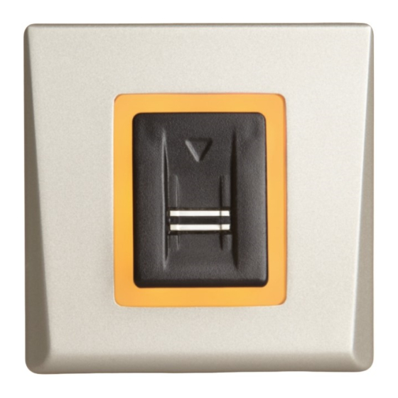
- Page 1 DINB100-SA Standalone Biometric Reader USER’S MANUAL...
-
Page 2: Table Of Contents
Contents .............. INTRODUCTION ..............MOUNTING ..............SPECIFICATIONS .............. APPLICATION DIAGRAM RECOMMENDED SWIPING TECHNIQUE ......................INDICATION WIRING ..........................ADDING ADMIN FINGER ......PAIRING - BIOMETRIC READER AND REMOTE RELAY UNIT ............Pairing DINB100-SA with DINRTT ............Pairing DINB100-SA with RTT ............ -
Page 3: Introduction
-10ºC or/and if the sensor could only be exposed to direct sunlight, it is strongly recommended to install the reader inside a third party sealed wall mount box (fitted with additional heater if very low temperature) to keep a constant sensor level performance. Videx™ cannot guarantee the functionality of the product if measures and advice before are not followed. -
Page 4: Specifications
Backlight ON/OFF: Buzzer ON/OFF: Firmware upgrade: via RS485 converter and windows application Current Consumption: 100 mA max. Power Supply: 9-14 V DC DINB100-SA v2 Indication: Tricolor Status LED IP Factor: IP40 Storage/Operating Temperature : -20°C to +50°C Storage/Operating Humidity: 5% to 93% RH without condensation... -
Page 5: Wiring
WIRING Relay Output Power Supply +12V Connection to additional (9-14V DC) Jumper (Adding Master Finger) card reader or keypad RS485 Push Button DINB100-SA v2 tamp tamp Tamper tamp tamp Electric Door Strike (DC powered) Exit Bu on (NO) GND(PB) tamp... -
Page 6: Pairing - Biometric Reader And Remote Relay Unit
Follow the instructions bellow to pair(couple) both devices or refer to the Remote Relay’s Manual. Pairing DINB100-SA with DINRTT 12 VDC 1. Close the Jumper. DINRTT beeps continuously and the red led blinks. DINB100-SA v2 DINRTT 2. Open the Jumper 3. Wait for Beep + OK Beep (short + short + long beep) -
Page 7: Administrator Programming
ADMINISTRATOR PROGRAMMING Use point fingers as Administrator and Installer. You can use the other fingers as access fingers. Administrator finger is enrolled at the end of the system installation. Initial enrollment of the Admin finger is described in installer manual. RIGHT LEFT ADD Finger Relay 1... -
Page 8: Delete Finger
CONNECTING DINB100 WITH DINMTPX PROXIMITY READER Connect both devices with the cable provided. The proximity reader will be powered via that cable. No extra power supply for the proximity reader is needed. DINB100-SA v2 DINMTPX Once connected, no further settings are needed. -
Page 9: Administrator Programming Block Diagram
Administrator Programming block diagram Swipe the ADMIN Finger 1 to 6 times depending of the desired menu swipes swipe swipes swipes swipes swipes Change Enroll ADD Finger ADD Finger ADD Finger ADMIN INSTALLER DELETE FINGER Relay 1 Relay 2 Relay 1&2 Finger Finger Wait... -
Page 10: Installer Programming
INSTALLER PROGRAMMING Set Relay 1 Time Action Finger Backlight Buzzer Sound Swipe Installer Finger 1 time short beep slow blinking short beep Wait 5 seconds (until fast blinking) Swipe the INSTALLER Finger fast blinking beeps on 1 second and start counting seconds Swipe the INSTALLER Finger to stop or wait 30 seconds to short + long beep... -
Page 11: Installer Programming Block Diagram
Installer Programming block diagram Swipe the Installer Finger 1 to 4 times depending of the desired menu swipe swipes swipes swipes BACKLIGHT BUZZER RELAY 1 RELAY 2 ON/OFF ON/OFF Time Time Wait Wait Wait Wait 5 seconds 5 seconds 5 seconds 5 seconds (until fast blinking) (until fast blinking) -
Page 12: Administrator Programming By Keypad
ADMINISTRATOR PROGRAMMING BY KEYPAD Programming by keypad can be done only if the DINB100-SA reader is connected to keypad DINPAD-M as shown in the pictures bellow. The connection is done by the cable provided with the biometric reader. Once connected, the keypad must be put in slave mode. - Page 13 ADMINISTRATOR PROGRAMMING BY KEYPAD Note: Entering this menu is done by ENTER ADMIN CODE default: 1234+A admin PIN Code. You can not enter with Admin Finger. Press 0A to exit the Menu MENU DELETE ENROLL ENROLL DELETE Installer Finger Admin Finger User User or PIN Code...
-
Page 14: Administrator Programming By Keypad
INSTALLER PROGRAMMING BY KEYPAD Note: Entering this menu is done by ENTER INSTALLER CODE installer PIN Code. You can not enter with Installer Finger. default: 5678+A MENU Press 0A to exit the Menu Buzzer Set Relay 1 Set Relay 2 Backlight ON/OFF TIME... - Page 16 This product herewith complies with requirements of EMC directive 2014/30/EU. In addition it complies with RoHS directive EN50581:2012 Northern Office Videx Security Ltd Unit 4-7 Chillingham ind Est Newcastle Upon Tyne NE6 2XX Tel: 0870 300 1240 Fax: 0191 224 5678...
Need help?
Do you have a question about the DINB100-SA v2 and is the answer not in the manual?
Questions and answers