Advertisement
Quick Links
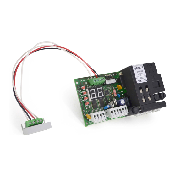
Q60A/R
CONTROL UNIT
FOR SWING GATE
SINGLE
OR DOUBLE LEAF 230V
8.8.
A
EXTERNAL
RADIO
B
PANEL
C
SI
+
D
NO
_
F5
1
2
M 2a
SELF-RESTORABLE FUSE 24V
IMPORTANT:
If a temporary short circuit occurs the fuse will
restore itself after few seconds.
8.8.
A
BUTTON A
Cycle round the top
level menu
B
DISPLAY
BUTTON B
Move from the top
DISPLAY SIGNALS
level menu to the lower
level menu
C
BUTTON C
SI
Increase time
+
or change to YES
D
BUTTON D
_
NO
Decrease time
or change to NO
CODE
FUNCTIONS
Show stored codes
New remote control
code acquisition
P C
Remote control code
acquisition with
STOP function
P
Remote control code
acquisition with
PEDESTRIAN function
C
Delete ALL remote
control codes
THE RADIO PANEL CAN ALSO BE PLACED
INSIDE THE BLINKER TO FURTHER IMPROVE
THE RADIO RANGE
EXTERNAL RADIO PANEL
Trasformer
230V / 23V
Aerial
CN
F4
24V
DISPLAY
AC
V2
AC
K1
K3
K2
F3
3
4
7
8
9
10
11
12
13
14
15
16
M 2b
M 3
In case of a permanent short circuit, cut the main power
off, remove the terminal blocks 2A and 2B, wait few
seconds and then power the unit again.
The fuse will be automatically restored.
Find and remove the short circuit cause before plugging
the terminal blocks in.
TOP LEVEL MENU
—
—
Opening
P
A
Closing
A
Delay time before
automatic Closing
A S
CODE
FUNCTIONS
P
Press & hold button C
to set defaults for
LEADER, ACE or SHARK.
ADVANTAGE MOTOR DEFAULTS
S
DISPLAY
Press & hold button C
I
to set defaults for
ADVANTAGE
WHEELER DRIVE DAFAULTS
2
Press & hold button C
to set defaults for
WHEELER
CONTROL UNIT COMPONENTS
A
top level menu button
B
lower level menu button
C
button to increase or change to yes (si)
D
button to decrease or change to no
F1
230V fuse 5A
F2
cocoon fusesfuse
F3
cocoon fusesfuse motor
230V
F4
24V fuse (self-restorable) 1,6A
L
N
F5
24V fuse (self-restorable) 0,65A
A B C
DISPLAY 7 SEGMENTS Display
M1
radio/aerial terminal block
V1
M2A/M2B Controls and safety devices terminal blocks
M3
motors terminal block
M4
main power terminal block
earth connections
Z2
A B C
MR
radio unit
CN
electrolock interface pcb connector
Z2
filter
K1/ K2
motors relay
F2
F1
K3
blinker relay
VI
Primary Varistor
V2
Secondary Varistor
17
18
19
20
M 4
DISPLAY
I
Motor 1 working time
0
2
Motor 2 working time
0
I F
I
Motor 1 Torque
8
F
2
Motor 2 Torque
8
STAND BY
F
Motor power during
PARAMETERS
deceleration
10
I
I
Motor 1
RADIO
deceleration time
0
2
Motor 2
DEFAULT
deceleration time
0
SEQUENTIAL
5
Motors' closing
PROGRAMMING
differential time delay
0
5
Motors' opening
differential delay time
0
P
Delay time before
automatic closing
0
FUNCTIONS
P
Pedestrian
Only
opening time
1 Motor
0
Lock pulse time
2 Motor
0=½ seconds, 1= 1 secs.
2=1½ secs. Etc........
motor
2 1,6 A
1 1,6 A
Tel. +39 0173 210111 - Fax +39 0173 210199
B
use button B to move to next parameter
C
use button C to INCREASE a numeric value or change NO to YES
D
use button D to DECREASE a numeric value or change YES to NO
To save changes and to ensure that they are not lost when power is
removed, use button B to step through
button C until the display reverts to idle display .
standard
advantage
wheeler
default
default
default
values
values
values
P
S
TIMES
21
13
9
Button B
99
21
13
9
99
14
10
12
19
14
10
12
19
19
19
19
19
7
4
4
(N1 - 2")
7
4
4
(N2 - 2")
3
3
2
N2
3
3
2
(N1 - 1)
3
3
3
99
7
7
3
(N1 - 1)
0
0
0
Proteco S.r.l. Via Neive, 77
12050 Castagnito (CN) ITALY
www.proteco.net - info@proteco.net
PARAMETERS
U S
parameter, the press and hold
standard
advantage
wheeler
default
default
default
values
values
values
P
S
FUNCTIONS
U S
Press & hold
button
NO
NO
NO
C to SAVE changes
Press
button D
to ABANDON changes
P
SOFT START
SI
SI
SI
8 P
Photocells test
SI
SI
SI
7 P
Motors test
SI
NO
SI
6 P
Deceleration on
SI
SI
SI
5 P
NO
NO
NO
Only one motor
4 P
NO
NO
NO
Pre blinking
P
Automatic closing
SI
SI
SI
step by step
2 P
Multi occupation
NO
NO
NO
I P
Electro lock
NO
NO
SI
O P
Reversing stroke
NO
NO
NO
06_prof._ Gb_2010
Advertisement

Related Manuals for Proteco Q60A

Summary of Contents for Proteco Q60A
- Page 1 Trasformer button to increase or change to yes (si) 230V / 23V CONTROL UNIT button to decrease or change to no Proteco S.r.l. Via Neive, 77 230V fuse 5A FOR SWING GATE Aerial 12050 Castagnito (CN) ITALY cocoon fusesfuse...
-
Page 2: Programming The Radio
PROGRAMMING THE RADIO PROGRAMMING THE Q60A PARAMETERS LLLLL IMPORTANT BEFORE PROGRAMMING FOR THE FIRST Method 1 = STANDARD TIME THE RADIO RECEIVER, DELETE ALL THE RECORDED TEST CODES. Method 2 = SEQUENTIAL SEQUENTIAL PROGRAMMING (method 2) SEE FUNCTION AT THE BOTTOM OF THIS CHAPTER... - Page 3 TERMINAL BLOCK CONNECTIONS All the connections must be done without power supply. EXTERNAL RADIO PANEL EARTH TERMINAL BLOCK CONNECTIONS Connect the yellow/green network cable and the yellow/green motor cables to earth terminals A B C. TERMINAL BLOCK 2 CONNECTIONS Start control normally open (NA) for button, key selector, radio receiver or Timer clock connections. The Start control starts the programmed running cycle.
- Page 4 WIRING SCHEME FOR THE Q60A CONTROL UNIT START PEDESTRIAN START First opening leaf, LEFT Terminal block 2b Terminal block 2a Terminal block 2b INSIDE Terminal block 3 M1 sx M2 dx YELLOW / GREEN PERMANENT START YELLOW / GREEN COMMAND WITH TIMER...
- Page 5 ONE MOTOR ONLY (RIGHT) CONNECTION ONE MOTOR ONLY (LEFT) CONNECTION WHEELER Terminal block 3 Terminal block 3 First opening leaf, RIGHT M1 dx M1 sx INSIDE Terminal block 3 M2 sx M1 dx YELLOW / GREEN YELLOW / GREEN YELLOW / GREEN SHARK YELLOW / GREEN First opening leaf, RIGHT...
- Page 6 ADVANTAGE CONNECTING PHOTOCELL IN CLOSING PHASE First opening leaf, RIGHT INSIDE RF 36 12V dc PHOTOCELLS CONNECTIONS Terminal block 3 24V dc 24V ca 8 = Power supply + PHOTO RX M2 sx M1 dx 9 = Power supply + PHOTO TX 12V dc 24V ac 10= Power supply - COM.
Need help?
Do you have a question about the Q60A and is the answer not in the manual?
Questions and answers
I connected proteco q60a/r 1-8 with flexess aqua (photo) purple and bleu ( is com and n.o. )for opening and closing gate Is that correct?