
Subscribe to Our Youtube Channel
Summary of Contents for Cybernetics V Series CY-miSAN-V
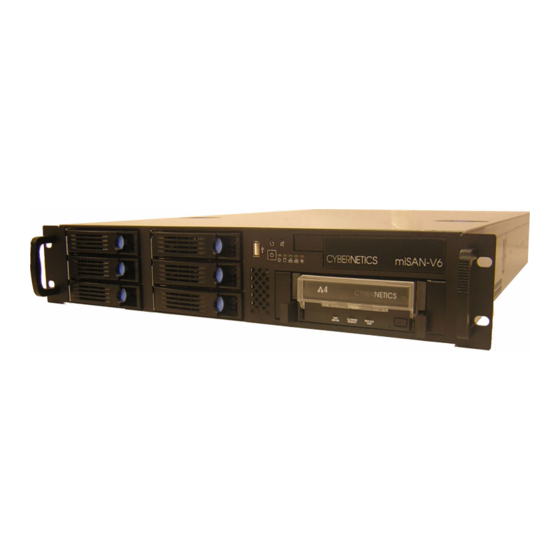
- Page 1 Operator’s miSAN-V-Series D2D2T Backup with removable AIT Tape Drive UM-MV-86 Rev. B1-0801 UM-MV-86-B1-0801 Cybernetics...
-
Page 2: Guide To Conventions
Guide to conventions Throughout the miSAN-V-Series manual, you will find caution and note boxes similar to those below. Please read the contents of the cautions and notes carefully. This icon indicates the existence of a potential hazard that could result in personal injury, damage to your equipment or loss of data if the safety instruction is not observed. -
Page 3: Table Of Contents
Table of Contents Guide to conventions ..........2 FCC Notice . - Page 4 Disk Storage ........
- Page 5 SNMPWEBCARD ............. 54 Data Compression .
- Page 6 Mounted Medium listbox........72 Autoload checkbox .
- Page 7 3DM2 Reference ........... 117 Controller Summary Page .
- Page 8 Operating ..........148 Appendix A Microsoft®...
- Page 9 Figure 2-1 miSAN-V-Series Rear Components......18 Figure 2-2 miSAN-V-Series Front Components ......20 Figure 2-3 “Confirm shutdown method”...
- Page 10 Figure 3-51 “Confirm data overwrite” Window ......95 Figure 3-52 “Manage volume tags” Window ......96 Figure 3-53 “Copy profiles”...
-
Page 11: Chapter 1 Introduction To The Misan
The miSAN-V-Series models use internal hot-swap disk drives for the virtual tape cache. The total storage capacity for the virtual tape cache is based on the number and configu- ration of the disk drives. For example, the miSAN-V-Series, with six internal disk drives of nearly 750 GB capacity each, will have about 4.5 TB of raw capacity available for the vir-... -
Page 12: Features
Standard miSAN-V-Series models include software support for virtual tapes, drives and libraries. Hardware support is offered for data backup and restoration using the integrated SCSI tape drive or via network with the iSCSI interface. The LVD parallel SCSI interface can allow the miSAN-V-Series to connect directly to a host system, either instead of or in addition to the iSCSI interface, allowing for off-network backup and data resto- ration. -
Page 13: Functionality
The RAID-based disk storage provides enhanced data integrity and security. The miSAN-V- Series makes efficient use of storage space and network bandwidth. It transfers stored data in raw block format without the overhead of traditional file systems. This can dramatically narrow the time required for even the most extensive backup schedule. -
Page 14: Web Control Panel
Introduction to the miSAN Web Control Panel The miSAN-V-Series offers a universally compatible Web Control Panel accessible through a network connection. The Web Control Panel is used for configuring, operating and viewing the status of the miSAN-V-Series in real-time. Multiple clients can access the interface using any Java™-enabled web browser. -
Page 15: Introduction
Introduction to the miSAN an illegitimate device on the network could perform a denial-of-service attack on the miSAN by sending it a SNMP message to shut down. Open Ports The miSAN has the following open ports: 23 Telnet 80 HTTP 162 SNMP-trap 888 3ware 3DM2 3260 iSCSI... - Page 16 Introduction to the miSAN SCSI host bus adapter (HBA) to the operating system and application software. To the host system, this appears to be a physical HBA, but all traffic for the iSCSI HBA is encap- sulated for delivery via the network to the remote iSCSI target. Host systems that will transmit commands and data via iSCSI should have iSCSI initiator software installed and configured.
-
Page 17: Chapter 2 Setting Up The Misan
Setting Up the miSAN This chapter provide requirements and instructions for unpacking and installing the miSAN-V-Series: • Installation Requirements • Installing the Hardware and Software Components • Connecting the Cables • Configuring the Network and iSCSI Settings • Setting Up the miSAN-V-Series Virtual Components •... -
Page 18: Installing The Hardware Components
Installing the Hardware Components Rackmount Installation The rackmount installation requires a 2U space in your rack. Follow the instructions included in the rackmount kit. Parallel SCSI Host systems that will transmit commands and data via a directly-connected SCSI inter- face to the miSAN-V-Series should have the host SCSI bus adapter installed and config- ured. -
Page 19: Network
Network Management LAN Port (ETH0) Using the Management LAN port, connect the miSAN-V-Series to your LAN using a CAT 5e or CAT 6 Ethernet cable. Please note that in some configurations the ETH0 port may be located in a different position than shown in the above illustration. Each port is clearly labeled. -
Page 20: Power Button
Series to a UPS. If you do not use a UPS, each power supply should be connected to a separate power main. Both power supplies must be connected to an AC power source, preferably separate power mains. The miSAN-V-Series uses both power suppl simultaneously to provide immediate failover in case one power supply fails If you use an APC®... -
Page 21: Configuring The Network And Iscsi Settings
Configuring the Network and iSCSI Settings The following sections include procedures for configuring the miSAN-V-Series network and iSCSI settings. You must complete the Network and iSCSI device configuration prior to initially using the miSAN-V-Series. Prerequisites Make sure to have the following available to allow for accessing the miSAN-V-Series on a private network: •... -
Page 22: Network Setup
Network Setup Certain network parameters must be changed to make the miSAN-V-Series visible on your network. 1. Open the web browser on the computer to the default Management LAN port (“ETH 0”) IP address at http://192.168.1.1 . A dialog box may appear asking for your approval to load the Web Control Panel Java applet. -
Page 23: Remote Iscsi Target Device Setup
The initiator and target are identified to each other by iSCSI Names. The iSCSI Names must be unique within the operational domain (networks encompassing the initiator and target), and are designed to be unique worldwide. The iSCSI Name may be permanently assigned to a hardware iSCSI device, or it may be constructed automatically as part of the process of installing an iSCSI software driver. -
Page 24: Misan-V-Series Iscsi Features
192.168.1.1 . Once the Web Control Panel has loaded, select Remote iSCSI Devices from miSAN- V-Series Options on the main menu bar. On the Remote iSCSI Devices window, set the following parameters: Remote iSCSI Devices Remote iSCSI device XSet this to Enabled to make the remote device visible to iSCSI host initiators. -
Page 25: The Administrator
2. Administrator • Can do anything except change encryption settings. • Configures menu settings, networking, iSCSI, virtual devices, etc. • Creates, deletes, and modifies VTs. • Configures the user account. • Can access SSH and telnet. 3. User • Limited set of abilities defined by the administrator. Only the administrator account is enabled by default. -
Page 26: The Security Officer
The Security Officer The security officer account is disabled by default. While the security officer account is disabled, the administrator has all the capabilities of the security officer. Enabling the security officer account takes away encryption-related capabilities from the administrator and reassigns them to the security officer. -
Page 27: Deciding How Many Virtual Tapes To Create
Choosing the number of virtual tapes to create involves deciding how to allocate the available miSAN-V-Series storage space. Factors to consider are the size of each physical tape, number of disk drives used by the miSAN-V-Series, total miSAN-V-Series disk storage capacity, tape car- tridge capacity, and historical/estimated compression ratio for backup data. -
Page 28: Virtual Standalone Drives
Virtual Standalone Drives Standalone drives are useful in cases where tapes are not assigned for different uses (e.g., when backups are typically large scale, spanning multiple tapes). For a virtual standalone drive, the miSAN-V-Series can automatically change the mounted tape, a method called autoloading, when using multiple tapes during a backup or restore. -
Page 29: Creating Virtual Devices
3. Select the “Create virtual tapes…” option. A window will appear showing the current number of virtual tapes and their disk space allocation over the total storage capacity. Caution Make sure to format the disks before creating virtual tapes for the first time. -
Page 30: Assigning Virtual Tapes To Virtual Devices
7. Click OK to save changes. The device tree on the “Devices” tab will refresh to update the configuration changes. Note Anytime the number of virtual devices is changed, the virtual tapes should be reassigned to the virtual devices. Assigning Virtual Tapes to Virtual Devices The virtual tapes can be assigned to a virtual device in either a random manner (e.g., VT 1.1, VT 1.3, VT 1.5, and VT 1.9) or a contiguous group (e.g., VT 1.1, VT 1.2, VT 1.3 and VT 1.4). -
Page 31: Testing The Installation
Using the IBM 3580 may require device drivers to be installed, which are available from the IBM FTP site (ftp://ftp.software.ibm.com/storage/devdrvr/). Drivers for the Overland NEO are not needed, although they are included with many backup applica- tions. -
Page 32: Figure 2-3 "Confirm Shutdown Method" Window
Note If the Host machine is connected to the miSAN-V-Series via Microsoft iSCSI Initiator software, it is necessary to log off the iSCSI connections before shutting down in order to avoid possible data loss. Failure to log off the iSCSI connections will cause Microsoft Windows to send “Unsafe Device Removal”... -
Page 33: Chapter 3 Operating The Web Control Panel
Operating the Web Control Panel Operating the Web Control Panel Interface Layout Introduction The miSAN-V-Series presents the Web Control Panel Java applet in an 800 frame (See Figure 3-1). You may have to adjust the screen size to accommodate the frame dimensions. -
Page 34: Tools
The Tools selection contains menu items that allow clients to configure the HSTC vir- tual components. The menu offers the following items, which are explained in the “Menu Descriptions” section: Disk storage, Create virtual tapes, Configure virtual devices, Assign virtual tapes, Physical stacker copy profiles, Configure auto-archive, Set date and time, Update license, Export or import configuration, Rescan physical devices, Logout admin, and Shut down the HSTC (See Figure 3-2). -
Page 35: Browser Links
Operating the Web Control Panel items, which are explained in the “Menu Descriptions” section: Product Information, SCSI Device List, Local iSCSI Initiator Name, Local iSCSI Target List and Credits and Licenses (See Figure 3-4). For further details see “Information” on page 69. Browser links The Browser links selection contains menu items that allow you to view information about the current miSAN-V-Series operating status, menu settings and hardware configurations. -
Page 36: Virtual Tape Tab
The menu offers the following items, which are explained in the “Menu Descriptions” sec- tion: Disk storage, Create virtual tapes, Configure virtual devices, Assign virtual tapes, Physical stacker copy profiles, Configure auto-archive, Set date and time, Update license, Export or import Cybernetics for more information. -
Page 37: Disk Storage
This item provides menu options for managing the miSAN-V-Series disk drives: • Manage disk storage : Opens a web-based GUI interface called the 3ware Disk Manager 2 (3DM® 2) that manages the integrated 3ware® Escalade® 9500S-8 SATA RAID controller. See page 109 for further instructions. -
Page 38: Create Virtual Tapes
Tools >Disk Storage Create Virtual Tapes This item allows for creating virtual tapes from the disk storage space available to the miSAN-V-Series. When selected, a window will appear showing the total number of virtual tapes and their disk space allocation over the total storage capacity (See Fig- ure 3-9). -
Page 39: Basic Tab
Operating the Web Control Panel To create a number of virtual tapes use either the Basic or Advanced tab: 1. Enter a “Number of virtual tapes.” 2. For the Advanced tab, choose to “Use all available space” or “Specify the tape size,”... -
Page 40: Advanced Tab
Operating the Web Control Panel the total storage capacity for all disks to create equally sized virtual tapes (See Figure 3-10). Figure 3-10 Create Virtual Tapes Basic Tab Advanced Tab The Advanced tab is used for specifying a disk to use for creating virtual tapes (See Figure 3-11). -
Page 41: Configure Virtual Devices
Operating the Web Control Panel Figure 3-12 Create Virtual Tapes “Format disks” Tab Caution Make sure to format the disks before creating virtual tapes for the first time. Failure to do so may cause errors when creating the virtual tapes. After creating tapes, remember that formatting the disks will erase the data stored on all disks used for the virtual tape cache. -
Page 42: Assign Virtual Tapes
Operating the Web Control Panel Figure 3-13 “Configure virtual devices” Window Assign Virtual Tapes This item allows for viewing and changing the assignments of the virtual tapes to the virtual devices. When this menu item is selected, a window will appear showing the current virtual tape assignments and any unassigned virtual tapes (See Figure 3-14). -
Page 43: Physical Stacker Copy Profiles
Operating the Web Control Panel Physical Stacker Copy Profiles Note This option only appears when the miSAN-V-Series is configured with optional Tape Library Control support and a tape library is connected. This item allows you to create copy profiles to use when enabling the Offload disk to tapes mode for a physical stacker. -
Page 44: Configure Auto-Archive
Operating the Web Control Panel clicking the -> button, which assigns the virtual tape name to the “Virtual tape” cell for that slot (See Figure 3-15). Once all the desired virtual tapes have been assigned, click Save changes to save the copy profile. The Help button provides an explanation of how to set up the associations. -
Page 45: Set Date And Time
Operating the Web Control Panel in the range, hold down SHIFT, and then click the last tape in the range. To assign the selected virtual tapes, click Add for the desired physical tape drive. Finally, choose the desired backup source: “... -
Page 46: Update License
Operating the Web Control Panel the “Messages” tab and for email messages sent from the miSAN-V-Series (See “Message Delivery” on page Figure 3-17 “Set date and time” Window Update License This item allows for entering license text provided by Cybernetics for changing the miSAN-V-Series model configuration. -
Page 47: Shut Down The Hstc
Operating the Web Control Panel standalone tape drive or tape library, the “Devices” folder on the “Devices” tab will refresh to allow for accessing and using the new device. Caution Since multiple clients can access and view the control panel simultaneously, users must not rescan for physical devices while other users are connected. -
Page 48: Figure 3-20 "Confirm Shutdown Method" Window
Operating the Web Control Panel Note If the Host machine is connected to the miSAN-V-Series via Microsoft iSCSI Initiator software, it is necessary to log off the iSCSI connections before shutting down in order to avoid possible data loss. Failure to log off the iSCSI connections will cause Microsoft Windows to send “Unsafe Device Removal”... -
Page 49: Hstc Options
Operating the Web Control Panel HSTC Options Configuration. Figure 3-21 Configuration Note Some of the options shown in the above menu will only be present if Compression or Encryption options are installed. Device ID order This option is only displayed when the miSAN-V-Series is configured for a virtual stacker. -
Page 50: Host Vs. Job I/O Policy
Operating the Web Control Panel An miSAN-V-Series with two standalone drives and one changer, Base SCSI ID set to 2 , and Device ID Order set to “Stacker then drives,” will use SCSI IDs as follows: An miSAN-V-Series with two virtual stackers, each with two virtual tape drives, with Base SCSI ID set to 0 , and Device ID Order set to “Drives then stacker,”... -
Page 51: Host I/O Idle Minutes
Operating the Web Control Panel policy will pause and remain in the running state but will not access the disk(s) until the host I/O finishes. Individual jobs can be configured to either use or ignore this setting’s policy. Jobs that ignore the policy run immediately without concern for the impact on the host’s available I/O bandwidth. -
Page 52: Drive Compression For Copying
Operating the Web Control Panel Drive compression for copying This option enables or disables internal tape drive data compression for con- nected tape devices (e.g., physical standalone or library tape drives). Note This feature can toggle drive data compression only if the tape drive is physically documentation for connected tape devices for information about drive compression settings. -
Page 53: Receive Snmp Messages From Ups
Operating the Web Control Panel “Advanced Options” menu. For each virtual device, select a tape device emulation for backup hosts to see and use. Note Device emulation may require a driver to be installed on the host computer system. Receive SNMP messages from UPS This menu option allows you to enable the HSTC to receive SNMP messages from an APC®... -
Page 54: Configuring A Tripp Lite® Smartpro®/Smartonline™ Model Ups With
Operating the Web Control Panel Note From the miSAN-V-Series’s Web Control Panel, make sure “Receive SNMP messages from UPS” is set to Enabled. To test the configuration, pull the AC power plug on the UPS. The “Messages” tab on the Web Control Panel should give a message that the UPS is on battery power. -
Page 55: Data Compression
Operating the Web Control Panel You do not have to configure “Settings” > “Network” > “SNMP”, because the HSTC does not send SNMP messages to the UPS; it only receives them. Note From the HSTC’s Web Control Panel, make sure “Receive SNMP messages from UPS”... -
Page 56: Scsi Configuration
Operating the Web Control Panel SCSI Configuration SCSI HBA Ports Depending on the miSAN-V series configuration, there will be HBA 1 and HBA2, or HBA 1a, HBA1b, HBA2a, and HBA2b. HBA 2 will normally be connected to a host, though it may be configured to connect to a target. HBA X direction Choose betwen Connects to host and Connects to devices. -
Page 57: Hba X Speed
Operating the Web Control Panel HBA X speed The “SCSI bus speed” setting defaults to “Auto.” The “Auto” setting provides the optimal bus speed for most configurations. To set a fixed, limiting bus speed, select from the wide and narrow speeds in the drop-down menu . . Note The actual SCSI bus speed negotiated between the miSAN-V-Series and the attached host system depends on the host hardware configuration... -
Page 58: Iscsi Host Password
Device X DNS Name or IP address Set this to match the DNS Name or IP address of the remote iSCSI device (tape drive, library, and/or iSCSI storage device (i.e. miSAN-D Series) with which the miSAN-V-Series is to communicate. Device X iSCSI Username Default is CyberneticsASP. - Page 59 Operating the Web Control Panel 2. Enable Remote iSCSI device 1. 3. Enter the IP address iSCSI device. 4. Enter iSCSI username (default iSCSI username is CyberneticsASP).. 5. Click on iSCSI password. Cybernetics UM-MV-86-B1-0801...
- Page 60 Operating the Web Control Panel 6. Enter new password. (Password must match the password on the iSCSI device and is recommended to be 14 characters long). Press OK . 7. A dialog box will pop up. Wait for it to disappear. 8.
- Page 61 Operating the Web Control Panel 10. Select Create virtual tapes... from the Tools drop-down menu. 11. Open the Format disks tab. Select either Format disks that need formatting , or Format all disks . After formatting the disks, press the Apply changes . 12.
-
Page 62: Network Configuration
Operating the Web Control Panel Network Configuration This submenu is used to configure the network interface(s). Based on the configura- tion, the unit may have three or more interfaces, which are used for either configura- tion and remote display only or for data transfer (iSCSI) as well. Each network interface may be configured individually. - Page 63 Operating the Web Control Panel interface, menu options are to enable the interface, and to set “IP address”, “sub- net mask”, and “MTU”. At least one network interface (“bond0”, “eth0”, “eth1”) must be Enabled . If all net- work interfaces are set to Disabled , attempting to save changes will give an error message.
-
Page 64: Ethx Ip Bonding
Operating the Web Control Panel If the user tries to save an invalid configuration, the miSAN-V-Series will display an error message. Return to the “Network Configuration” menu so that the conflict can be corrected or the changes cancelled. Two or more interfaces may be “bonded” together to transfer data as a single Ethernet interface “bondX”. -
Page 65: Bondx
Operating the Web Control Panel bond X Note This menu item only appears when two or more Ethernet interfaces are set to “Bonded”. Settings for “bondX IP address”, “bondX subnet mask” and “bondX MTU” will be shown only if Bonding is set to Enabled . However, settings for the “eth”... -
Page 66: Send Messages By Email
Operating the Web Control Panel • “ ” line: Given as the miSAN-V-Series “Hostname,” as set in the “Network From Configuration” menu (See address “ techsupport@cybernetics.com • “ ” line: Reply-To <techsupport@cybernetics.com> address is supplied for miSAN-V-Series email recipients who need assistance after receiving a message reporting an error. -
Page 67: Accounts
Operating the Web Control Panel separate each with a semi-colon (‘;’) followed by a space. For example: techsupport@domain.com; webmaster@domain,com; admin@domain.com Accounts This sub-menu sets a password for restricting access to the Java Web Control Panel and the Telnet Menu System. For the Web Control Panel, this password is used to load the Java applet. -
Page 68: Advanced Options
Operating the Web Control Panel To disable password authentication (remove an existing password), clear the cur- rent entry without entering a new password, and then save the change. The following options apply to the user account: • User may offload to PTs (Disabled or Enabled). •... -
Page 69: Debugging
Operating the Web Control Panel The configured emulations can be selected for use by virtual devices using the “Virtual Device Emulations” menu (See Note Enabling support for each emulation requires a passcode. Contact Cybernetics Technical Support to identify numbered emulations and obtain passcodes for specific manufacturer models. -
Page 70: Physical Devices
Operating the Web Control Panel “Flags” are installed con figuration options, such as “ASP”, “iSCSI-HOST” and “iSCSI DEVICE.” If no options are installed, this line will simply display “Flags:” Note The network settings (IP address/subnet mask) and MAC address will be shown for each installed network interface. -
Page 71: Tabs
Operating the Web Control Panel Tabs Devices Tab The “Devices” tab shows a “tree” view on the left with an entry representing each virtual and physical device (physically attached or connected via iSCSI) (See Figure 3-22). Vir- tual tape drives and stackers (libraries) appear as numbered “VirtTapeDrive” and “Virt- Stacker”... -
Page 72: Virtual Tape Drive Device Panel
Operating the Web Control Panel Virtual Tape Drive Device Panel When selected in the device tree, a virtual standalone tape drive will expand to reveal a device panel in the frame on the “Devices” tab (See Figure 3-24). The device panel presents a “Mounted medium”... -
Page 73: Figure 3-25 Virtual Stacker Device Panel
Operating the Web Control Panel • Stacker slots are presented as a table with columns for the following fields: • Element: Numbered virtual stacker slots and tape drive(s) • Tape: Tapes presented in the virtual stacker slots and drive(s) • The “Tape”... -
Page 74: Figure 3-26 "Move To Slot" Popup Menu
Operating the Web Control Panel another slot (See Figure 3-26) or drive (See Figure 3-27). Unavailable slots and drives are greyed out. Figure 3-26 “Move to slot” Popup Menu Figure 3-27 “Move to drive” Popup Menu Cybernetics UM-MV-86-B1-0801... -
Page 75: Physical Tape Drive Device Panel
Operating the Web Control Panel Physical Tape Drive Device Panel When selected in the device tree, a physical tape drive will reveal a device panel in the frame on the “Devices” tab. The device panel presents the status informa- tion for the tape drive (See Figure 3-28). Figure 3-28 Physical Tape Drive Device Panel The physical tape drive status information is presented with the following fields: •... -
Page 76: Menu Button
Operating the Web Control Panel • Tape status : Tape cartridge load status, which reports “Loaded” when ready for use. For a “Loaded” tape cartridge, “MEDIUM ERROR” will also appear if a loaded tape has a problem that prevents the drive from reading or writing data, and “Write-protected”... -
Page 77: Figure 3-29 "Setup Offload" Window
Operating the Web Control Panel This option allows for setting up offloading from a virtual tape to the physical tape drive. Figure 3-29 “Setup offload” Window To specify which virtual tape to be offloaded to the physical tape: 1) Click Select VT to offload... 2) Select the virtual tape you want to copy to the physical tape. -
Page 78: Figure 3-31 "Clear Vt For Offloading" Option
Operating the Web Control Panel You can clear the association between a physical tape and the virtual tape for off- loading from the “Physical tapes” tab. Figure 3-31 “Clear VT for offloading” Option • Action After you choose a virtual tape to be offloaded to a physical tape, you may select one of the following actions to be performed to the virtual tape: Do nothing to VT –... -
Page 79: Figure 3-32 "Offload Disk To Tape" Window
Operating the Web Control Panel An alternative way to purge the record of an old backup from your backup soft- ware’s database is to use “Host access” to have your software erase the physical tape (See “Host access” on page manually through your software. -
Page 80: Figure 3-33 "Load Tape Onto Disk" Window
Operating the Web Control Panel The “Source and Destination” frame shows the name of the source (“Virtual tape”) and destination (“Physical tape”) for offloading the tape. Click “Select VT to offload...”, and then choose the virtual tape to set the source. “Offload status”... -
Page 81: Host Access
Operating the Web Control Panel Host access Host access enables you to access the physical tape drive directly from your soft- ware, bypassing the disk cache. This is often useful for restoring directly from a physical tape. Enabling host access Choose one of the virtual devices listed in the “Host access”... -
Page 82: Physical Stacker Device Panel
Operating the Web Control Panel Physical Stacker Device Panel Note This section only applies if the miSAN-V-Series is configured with Tape Library Control support. The physical stacker device panel is only used when the miSAN-V-Series is configured to operate an external tape library. -
Page 83: Figure 3-34 Physical Stacker Device Panel
Operating the Web Control Panel • Tape – Tapes inserted in the physical library slots and drive(s) Figure 3-34 Physical Stacker Device Panel All control and jobs for the physical stacker are initiated using commands avail- able from a popup menu. To access the popup menu, right-click in the stacker table. -
Page 84: Figure 3-35 "Setup Offload" Window
Operating the Web Control Panel • Tape capacity, used space, and free space • Write-protect status If the tape has a serial number, then the “Inventory tapes...” option can be used to identify the tape from the database of known tapes. •... - Page 85 Operating the Web Control Panel select one of the actions, right-click the row for the desired physical tape/virtual tape assignment, and choose the “Set action” menu option. Do nothing to VT – Choose this if the virtual tape already contains a backup you want to offload to the physical tape.
-
Page 86: Figure 3-37 "Wait For Backup" Option
Operating the Web Control Panel for backup” is selected by default if you choose “Erase VT” or if the virtual tape is already blank, but you can deselect it if desired Figure 3-37 “Wait for backup” Option You can clear the association between a physical tape and the virtual tape for off- loading from the “Physical tapes”... -
Page 87: Figure 3-39 "Copy Selections" Tab
Operating the Web Control Panel The “Copy selections” tab is used to offload the set of virtual tapes specified using the “Setup offload...”option to the physical tapes. Figure 3-39 “Copy selections” Tab The “Copy profiles” frame (See Figure 3-40) allows for selecting and using one of the saved copy profiles to automatically assign virtual tapes to physical tapes (See “Physical Stacker Copy Profiles”... - Page 88 Operating the Web Control Panel Continue running jobs even when tapes are changed (requires a copy pro- file) – This option lets you offload a specific set of virtual tapes to any physical tapes that you load in specific slots in the stacker. The jobs will continue to run even when you open the stacker door and change the physical tapes.
-
Page 89: Figure 3-42 "Load Tapes Onto Disk" Window
Operating the Web Control Panel physical stacker and a table, on the right, with all the virtual tapes assigned to devices (See Figure 3-42). Figure 3-42 “Load tapes onto disk” Window To assign a physical tape to a virtual tape for copying, first, select the desired physical tape cartridge in the “Physical tapes”... - Page 90 Operating the Web Control Panel Enabling host access 1) Choose the slot(s) in the physical stacker that you want to allow host access; you can select slots individually or in a contiguous group: To allow host access to the physical stacker using a virtual tape drive, select only one slot.
-
Page 91: Properties Tab
Operating the Web Control Panel Properties tab The “Properties” tab gives the following information: the model, firmware version, serial number, stacker type (“Normal stacker” or “Autoloader”), number of slots, number of import/export slots, and number of tape drives. Figure 3-44 Physical Stacker “Properties” Tab The “Properties”... -
Page 92: Figure 3-45 Optical Drive Device Panel
Caution The size of the virtual tape to be copied to the optical disc must not be larger than the optical disc storage capacity, else the copied virtual tape will be truncated and incomplete. After clicking Backup a VT , a window will appear with a drop-down listbox that includes all the virtual tapes. -
Page 93: Virtual Tapes Tab
Operating the Web Control Panel Figure 3-46 “Select virtual tape to backup” Window Virtual Tapes Tab The “Virtual tapes” tab shows the current status of each miSAN-V-Series virtual tape. Status Fields The virtual tape cache is presented as a table with rows for each virtual tape and col- umns for the following tape fields (See Figure 3-47): •... -
Page 94: Virtual Tape Popup Menu
Operating the Web Control Panel Virtual Tape Popup Menu Virtual tape control is handled using a popup menu (See Figure 3-48). Figure 3-48 Virtual Tape Popup Menu The virtual tape popup menu is accessed by first selecting the desired virtual tape and then right-clicking it. -
Page 95: Figure 3-50 "Select Copy Destination" Window
Operating the Web Control Panel volume tag will allow the virtual tape to appear as if it has been replaced by a new empty tape in the virtual device. Copy to another VT: Used to initiate a copy from the virtual tape to another virtual tape. -
Page 96: Bar Code
Operating the Web Control Panel Bar code: Note This tab can only be used when the miSAN-V-Series is configured with Tape Library Control support and is configured to operate an external tape library that reports barcodes. Use the Physical tapes tab to select and assign a volume tag from the bar code labels on the tapes in the physical stacker. -
Page 97: Physical Tapes Tab
Operating the Web Control Panel number (0-65535). The OK button sets and the Clear button erases the volume tag. Be sure not to assign the same volume tag to more than one virtual tape. Figure 3-54 “Edit” Tab for Volume Tags •... -
Page 98: Status Fields
Operating the Web Control Panel their copied virtual tapes. When a backup of a virtual tape begins, its associated phys- ical tapes will be used. Whenever the library door is opened and then closed, the tape status for all physical tapes is automatically refreshed. -
Page 99: Jobs Tab
Operating the Web Control Panel Jobs Tab The HSTC uses jobs to do its own internal work such as offloading virtual tapes to physical tapes. These jobs are similar in concept but separate from the jobs that your backup software may use to do backups and restores. The HSTC performs the following types of jobs: •... -
Page 100: Job Log
Operating the Web Control Panel • State : Indicates one of the following states: • “Running” – Either Actively doing work, waiting for some trigger condition, or waiting for a required resource to become available • “Suspended” – Not doing any work until you manually resume it •... -
Page 101: Activity Monitor
Operating the Web Control Panel You can copy the “Job log” contents to the clipboard by first right-clicking in the “Job” log, from the popup menu, selecting “Copy to clipboard”, and then pasting the text into a text editor. Figure 3-58 Exporting the “Job log” You can export the entire “Jobs”... -
Page 102: Messages Tab
USB disks are intended for offloading Virtual Tapes rather than being used as primary storage, so the HSTC treats USB disks slightly differently than other disks. A USB disk will show up in the Java applet under the physical device tree with its own panel of infor- mation and controls, just like a physical tape drive would. - Page 103 Operating the Web Control Panel 1) "Create VTs" - this brings up the same window as "Tools->Create virtual tapes...", except that it is specifically for the one USB disk only. You may create multiple VTs on one USB disk, just like any other disk drive. Note that "Tools->Create virtual tapes..." does not list USB disks.
- Page 104 Operating the Web Control Panel Cybernetics UM-MV-86-B1-0801...
-
Page 105: Chapter 4 Telnet Menu System
Telnet Menu System Telnet Menu System This section describes the telnet menu system available used for configuration and oper- ation of the miSAN-V-Series. To use the telnet menu system, the unit must be powered on and fully initialized. To con- nect, open a standard telnet or terminal emulation program on a host system connected to the local network. -
Page 106: Misan-V-Series Messages
miSAN-V-Series Messages The miSAN-V-Series may on occasion need to display a message to the user. Messages are displayed during startup initialization or to announce completion of an offline opera- tion or to request user confirmation of an action. When the menu system is being accessed, all messages will be held by the miSAN-V- Series. -
Page 107: Scsi Configuration
The “Main Menu” and each submenu include an item marked: x) Exit If if any changes are made to the information, the changes are not committed until after leaving the menu system. The exit item will change to a pair of menu items: s) Save changes and exit x) Discard changes and exit Type s or x as desired, to exit the menu with changes saved or not. -
Page 108: Swap Scsi Hba Ports
Swap SCSI HBA ports Offline Maintenance Note This menu option and its submenu item are only available using the Telnet Menu System. This menu is used for maintenance such as uploading hardware code or debugging. While the miSAN-V-Series is in this mode, all connected SCSI devices will be “offline” and unavailable to a host computer system. -
Page 109: Reset Options To Defaults
Load board code This menu item loads firmware into the miSAN-V-Series from a connected physical tape drive or via a TCP/IP network connection, for code upgrades as directed by Cybernetics Technical Support. Reset options to defaults This menu item resets all settings to default values. Do not do this unless directed by Cybernetics Technical Support. - Page 110 Telnet Menu System Cybernetics UM-MV-86-B1-0801...
-
Page 111: Chapter 5 Using The 3Ware Disk Manager
Note 3DM can be used while the drives are online, but changing the RAID configuration will fail because the disks will be mounted. “Disk Storage” on page 40 they can be reconfigured. Browser Requirements 3DM 2 (3ware Disk Manager) displays information in a web browser. It requires the fol- lowing: •... -
Page 112: Logging In
Using the 3ware Disk Manager® Logging In When you first view 3DM in a browser, you must log in before you can view or change any information. Two levels of access are provided: • User can check the status of the controller, units, and drives attached to it. •... -
Page 113: 3Dm Menus
Using the 3ware Disk Manager® The menu bar across the top of the screen gives you access to other pages in 3DM. You can move between pages by using the menu bar, or by clicking a link on the page. The main area of the page provides summary or detail information about your 3ware RAID controller and the resources connected to it. -
Page 114: 3Dm Screens And What They're Used For
Using the 3ware Disk Manager® 3DM Screens and What They're Used For 3DM Page Description Controller Summary Provides basic information the 3ware RAID controller in the miSAN-V-Series. To see this page, click Summary in the menu bar. Controller Details Provides detailed information about the current controller. To see this page, choose Information >... -
Page 115: Setting Up 3Dm Preferences
Using the 3ware Disk Manager® Setting Up 3DM Preferences The 3DM Settings page allows for defining preference settings that affect the overall operation of 3DM. Most of these settings are factory-set during installation of 3DM. Setting and Changing 3DM Passwords 3DM provides different access levels for users and administrators. -
Page 116: Caution About Disabling Remote Access
Do not change the Incoming Port # from the default 888. If the Incoming Port # default is changed from 888, the Web Control Panel will not be able to open 3DM using the Manage disk storage option. (See “Disk Storage” on page 67). -
Page 117: 3Dm2 Reference
Using the 3ware Disk Manager® To set the frequency of page refreshes: 1. Click 3DM Settings on the menu bar. 2. In the Page Refresh section of the 3DM Settings page, select how often you want you want the page to be refreshed in the Minutes Between Refresh field. Note If you don’t want 3DM to refresh the screen automatically, select Never in the Minutes Between Refresh field. -
Page 118: Controller Summary Page
Using the 3ware Disk Manager® Controller Summary Page Figure 5-3 Controller Summary Page The Summary page appears after you first logon to 3DM, and when you click the Sum- mary link in the menu bar. The Summary page provides basic information about each 3ware RAID controller in your system. -
Page 119: Controller Details Page
Using the 3ware Disk Manager® Controller Details Page Figure 5-4 Controller Details Page The Controller Details page appears when you choose Information > Controller Details from the menu bar. The Controller Details page provides detailed information about the controller specified in the drop-down list on the menu bar. -
Page 120: Unit Information Page
Using the 3ware Disk Manager® Unit Information Page The Unit Information page appears when you choose Information > Unit Information from the menu bar, and when you click an ID number on the Controller Summary page. The Unit Information page shows a list of the units on the controller specified in the drop- down list on the menu bar and provides summary information about each unit. -
Page 121: Unit Details Page
Using the 3ware Disk Manager® Unit Details Page The Unit Details page appears when you click an ID number on the Unit Information page. Since it is a sub-page of Unit Information, the page title in the menu bar continues to display “Unit Information”... -
Page 122: Drive Information Page
1K = 1000. Consequently, the capacity of the drive may appear smaller in the 3DM screens. No storage capacity is actually lost; the size has simply been calculated differently for consistency. -
Page 123: Smart Details About Drive At Particular Port Page
Using the 3ware Disk Manager® • Firmware : The firmware version of the drive. • Unit : The unit the drive belongs to, if applicable. • Status : The status of the drive: OK, Not Supported, Read Timeout, Read Failure, Orphan, DCB Data Check, Unsupp DCB, Unconv DCB, Offline JBOD, or Not Present. -
Page 124: Controller Settings Page
Using the 3ware Disk Manager® Controller Settings Page Figure 5-9 Controller Settings Page The Controller Settings page appears when you choose Management > Controller Set- tings from the menu bar. The Controller Settings page lets you view and change settings that affect the units on the controller specified in the drop-down list on the menu bar. -
Page 125: Background Task Rate
Using the 3ware Disk Manager® Background Task Rate The Background Task Rate fields let you change the balance of background tasks and I/ O performed by the controller. The 5 radio buttons let you set the ratio at which background tasks are performed in com- parison to I/O. -
Page 126: Unit Names
Using the 3ware Disk Manager® manually. It is recommended that a file system check be executed when the rebuild completes. Unit Names Units can be assigned names. A name can be assigned when the unit is created and can be changed from this screen. Other Controller Settings •... -
Page 127: Scheduling Page
Using the 3ware Disk Manager® Scheduling Page The Scheduling page appears when you choose Management > Scheduling from the menu bar. The Scheduling page lets you view and change the schedule for background tasks that affect all units on the controller specified in the drop-down list on the menu bar, including: •... -
Page 128: About Task Schedules
Using the 3ware Disk Manager® About Task Schedules Each type of task may be scheduled for up to seven times per week. This limits active ini- tializing, rebuilding, verifying, and testing of a unit to the times you specify, so that the task does not interfere with peak I/O times. -
Page 129: Maintenance Page
Using the 3ware Disk Manager® Maintenance Page The Maintenance page appears when you choose Management > Maintenance from the menu bar. The Maintenance page lets you perform maintenance tasks on existing units on the current controller (shown in the drop-down list on the menu bar), and lets you create new units by configuring available drives. -
Page 130: Unit Maintenance
Using the 3ware Disk Manager® In addition, if there is a unit with the status Inoperable before a rescan (for example, a RAID 5 unit missing two or more drives), and a rescan finds drives that complete the unit, the inoperable unit will become a valid unit. Unit Maintenance The Unit Maintenance section of the page lists all existing units on the current controller, and displays summary information about them. -
Page 131: Maintenance Task Buttons
Using the 3ware Disk Manager® Maintenance Task Buttons Below the list of units, a row of task buttons lets you preform maintenance and configura- tion tasks related to the unit. Before clicking one of these buttons, select the appropriate unit: •... -
Page 132: Available Drives (To Create Units)
Using the 3ware Disk Manager® Available Drives (to Create Units) This section lists the drives on the controller which are not currently configured as part of a unit. The Port number, model, capacity, and status are all displayed, as they are for drives in existing units. -
Page 133: Alarms Page
Using the 3ware Disk Manager® Alarms Page The Alarms page appears when you click Alarms on the menu bar. This page displays a list of AENs (Asynchronous Event Notifications) received from the controller displayed in the drop-down list in the menu bar. Up to 1000 alarms can be listed. -
Page 134: 3Dm Settings Page
Using the 3ware Disk Manager® 3DM Settings Page The 3DM Settings page appears when you click 3DM Settings on the menu bar. Use this page to set preferences, including email notification for alarms, passwords, page refresh frequency, whether remote access is permitted, and the incoming port for 3DM to listen for requests. -
Page 135: E-Mail Notification
Using the 3ware Disk Manager® E-mail Notification Use the fields in this section to set up and manage notifications of events by e-mail. Send E-mail : This field determines whether e-mail notification is Enabled or Disabled. • • Send Severity and Above : Specifies the type of events for which notifications should be sent. -
Page 136: Remote Access
Do not change the Incoming Port # from the default 888. If the Incoming Port # default is changed from 888, the Web Control Panel will not be able to open 3DM using the Manage disk storage option (See “Disk Storage” on page 67. -
Page 137: Type Of Raid Configuration
Using the 3ware Disk Manager® before they can be used. If you want to add drives to be used in the unit, see Drive” on page 138. Type of RAID Configuration Available configuration types include RAID 0, RAID 1, RAID 5, RAID 10, RAID 50 and Single Disk. -
Page 138: Configuring Drives
3DM. It’s a good idea to select a hot spare after you create a redundant unit. In order to replace a failed drive, a hot spare must have the same or larger storage capacity than the drives it is replacing. -
Page 139: Figure 5-13 Removing A Drive In 3Dm
Using the 3ware Disk Manager® This is useful if you know that a drive is developing a problem and you want to replace it, or to replace a drive which has already failed. Caution If you unplug a drive without first removing it through 3DM, Rescan will not recognize it as gone. -
Page 140: Figure 5-14 Result Of Removing Drive From Unit In 3Dm
Using the 3ware Disk Manager® You can now remove the drive from your system. If you removed a drive that was part of a unit, the unit may become degraded. Figure 5-14 Result of Removing Drive from Unit in 3DM Cybernetics UM-MV-86-B1-0801... -
Page 141: Chapter 6 Packing And Shipping Instructions
Packing and Shipping Instructions Packing and Shipping Instructions This chapter provides instructions for transporting the miSAN-V-Series or returning the miSAN-V-Series to Cybernetics for service or repair. The packing and shipping process involves first removing the miSAN-V-Series from the place where it is installed, enclosing the unit in an anti-static bag, and then placing the miSAN-V-Series in the packing materi- als. -
Page 142: Using The Proper Packing Materials
Packing and Shipping Instructions Using the Proper Packing Materials You must use the original packing materials that came with the miSAN-V-Series from Cybernetics. Replacement packing materials can be purchased by contacting Cybernet- ics’ Technical Support at (757) 833-9200. Note Styrofoam pellets or “peanuts” are not adequate for packing, since they may shift and allow the miSAN-V-Series to move about in the shipping box. - Page 143 Packing and Shipping Instructions To prepare the chassis for shipping, complete the following steps: 1. Enclose the unit in an anti-static bag to prevent ESD damage. 2. Place the Cybernetics box on a level surface. 3. Place one of the cardboard shellsl (identified in “Using the Proper Packing Materials” on page 142) plastic-side up at the bottom of the Cybernetics box.
- Page 144 Packing and Shipping Instructions 5. Place the second cardboard shell on top of the chassis. 6. Open the accessory box, place the accessories inside (e.g., cables, terminators, and AC power cord), if requested by Cybernetics, and close the box. 7. Place the two filler boxes on top of the cardboard shell. Cybernetics UM-MV-86-B1-0801...
- Page 145 Packing and Shipping Instructions 8. Place the accessory box on top of the cardboard shell and if you are returning the rackmount kit, place it next to the accessory box as shown in the bottom right picture.. 9. The figure below illustrates the previous steps. 10.
- Page 146 Packing and Shipping Instructions Cybernetics UM-MV-86-B1-0801...
-
Page 147: Chapter 7 Product Specifications
Product Specifications Supported iSCSI Initiators Microsoft iSCSI Initiator 2.0 or higher Windows XP/2000/2003 Server http://www.microsoft.com/downloads/details.aspx?FamilyID=12cb3c1a-15d6-4585-b385- befd1319f825&displaylang=en Cisco iSCSI Driver 3.x Sun Solaris 7/8/9 Go to http://www.cisco.com/univercd/cc/td/doc/product/sn5000/sn5400/iscsidrv/index.htm Sun Solaris 10 Go to http://www.sunsolve.sun.com/search/document.do?assetkey=1-21-119090-20-1 QLogic SANblade iSCSI HBA QLA4010C Windows 2000/2003 Server, Sun Solaris SPARC, Linux (32-bit and 64-bit) Go to http://www.qlogic.com/support/product_resources.asp?id=341 Protocols and Standards... -
Page 148: Iscsi Network Ports (Eth1, Eth2)
iSCSI Network Ports (ETH1, ETH2) 10/100/1000Base-T (1 Gigabit/sec.) TCP/IP RJ-45 connector SCSI Parallel Interfaces Low Voltage Differential (LVD) VHDCI 68-pin, female socket Ultra3 (Ultra160) Wide SCSI Maximum synchronous data transfer rate of 160 megabytes/sec. Auto-selectable between LVD and Single-Ended (SE) mode Physical Dimensions Height Width, chassis... -
Page 149: Appendix A Microsoft® Iscsi Initiator Software Client
Microsoft ® Host systems running Microsoft® Windows® 2000, XP or 2003 can access Cybernetics iSCSI devices using the Microsoft iSCSI Initiator software. The following sections provide detailed steps for downloading and running the setup program and installing and config- uring the driver. The following information is subject to change by Microsoft. The screen shots that follow may be different than what will show on your computer, depending on what software you are running, and whether you are updating or newly installing the Microsoft®... - Page 150 4. Scroll down to the “Files in this Download” section, and then click the applicable “fre” link for a 32-bit (“x86”) or 64-bit (“ia64”) system. 5. Click Save in the “File Download” dialog box. Note It is also recommended that you download and study the release notes and user guide.
-
Page 151: Installing The Software
6. Choose a location for the file in the Save As dialog box, and then click Save . The file is then saved to the specified location. Installing the Software To install and set up the iSCSI Initiator software, complete the following steps: Note The information presented here is provided as a courtesy only and may not reflect the current software version provided by Microsoft. - Page 152 2. Click Next to continue. 3. Read the license agreement in the “License Agreement” window, select “I agree,” and then click Next . Cybernetics UM-MV-86-B1-0801...
- Page 153 4. Choose a location to install the driver files in the “Select Installation Folder” window, and then click Next to continue. Note The ability to select a location for the installation of the Microsoft iSCSI Initiator is only available for new installations. If you are upgrading to a newer version of the initiator, the options will be different than shown here.
-
Page 154: Configuring The Iscsi Initiator
The Microsoft iSCSI Installation Program will execute once the setup files have been copied. 6. Choose to “Install Complete iSCSI Initiator,” and then click OK . Configuring the iSCSI Initiator The iSCSI Initiator Properties window is used for configuring the driver and can be accessed by launching the “iSCSI Initiator”... -
Page 155: Changing Initiator Node Name
Make a note of the “initiator node name,” which can be used by Cybernetics iSCSI devices for assigning control of storage resources. This name is displayed on the “Gen- eral” tab and can be changed if a target has not yet been assigned to it. To change the name, click the “Change”... -
Page 156: Figure A-1 Advanced Settings
3. Clicking Advanced... allows access to security settings, such as CHAP authentication, which is supported by Cybernetics iSCSI devices. The CHAP password must be between 12 and 16 characters. Cybernetics Figure A-1 Advanced Settings UM-MV-86-B1-0801... - Page 157 Select the “Targets” tab to view the iSCSI targets discovered through the added target portals. To log onto an iSCSI target, select it from the list, and then click Log On... 4. Select the option to “Automatically restore this connection when the system boots” to make a target persistent, so the iSCSI Initiator will attempt to reconnect to it each time the computer is rebooted.
-
Page 158: Creating System Dependencies
Using iSCSI Disk Devices with the iSCSI Initiator When using an iSCSI disk device to create file shares (e.g., for network storage, backup copies, e-mail), the iSCSI Initiator service needs to start before the Server service, which creates file shares. This is because the Server service cannot create file shares for iSCSI disk devices until the iSCSI Initiator service is initialized. - Page 159 3. Select lanmanserver 4. Select Edit > Add value... from the menu bar 5. Enter the Value Name 6. Select REG_MULTI_SZ 7. Click OK 8. Make the value DependOnService 9. After you are finished editing the registry, be sure to restart the computer to make sure the settings will take effect.
-
Page 160: Using Backup Software With The Iscsi Initiator
Using Backup Software with the iSCSI Initiator When using backup software with the Microsoft® iSCSI Initiator, the iSCSI Initiator ser- vice needs to start before the backup software services. This ensures the backup soft- ware will be able to detect the SCSI devices that the iSCSI Initiator logs into. This requires starting the services in a specific sequence. -
Page 161: Logging Off
Initiator service MSiSCSI LanmanWorkstation 5. After you are finished editing the registry, be sure to restart the computer to make sure the settings will take effect. Logging Off Caution It is necessary to log off the iSCSI connections before shutting down a target in order to avoid possible data loss. - Page 162 2. Highlight one of the targets and press “Details” 3. Click “Log off”. 4. Repeat the process for each target on the machine you are shutting down. Cybernetics UM-MV-86-B1-0801...
-
Page 163: Appendix B Linux Iscsi Initiator
Linux iSCSI Initiator Introduction There are many variations of Linux available. Your installation and configuration of Linux may be different than those mentioned later in this Appendix. Cybernetics takes no responsibility for any of the code recommendations or content of the links provided. Before starting, determine the kernel version being used by typing uname -r The project page for Linux iSCSI is: The linux-iscsi driver began as an open source version of the Cisco iSCSI Initiator. -
Page 164: Core-Iscsi Setup
The project does not have a web page. It has an active discussion board at groups.google.com/group/core-iscsi core-iscsi Initiator: http://www.kernel.org/pub/linux/kernel/people/nab/iscsi-initiator-core/ core-iscsi-tools: http://www.kernel.org/pub/linux/utils/storage/iscsi/ Core-iSCSI Setup The configuration file is /etc/sysconfig/initiator, and the syntax is different from linux- iscsi's /etc/iscsi.conf. For an iTape/HSTC, you need a line like: CHANNEL="0 1 eth0 192.168.1.1 3260 0 HeaderDigest=None;DataDigest=None"... -
Page 165: Red Hat 9 & Enterprise Linux 3
Red Hat 9 & Enterprise Linux 3 To install an RPM: Go to http://sourceforge.net/projects/linux-iscsi for your distro version. Install from the RPM - run `rpm -i rpmfile` SuSE Linux Pro 9.1 The package name is linux-iscsi (version 4.0.1-83). This initiator works with cy-iscsi prod- ucts (hstc, misan, itape). - Page 166 Also, try a tar to write & read to the drive. `tar -cvf /dev/st0 /somedir` will backup the "somedir" directory. `tar -tvf /dev/st0` will display the file listing on the drive. `tar -xvf /dev/ st0 /somedir` will restore to the "somedir" directory. Cybernetics UM-MV-12-B1-0801...
-
Page 167: Appendix C Glossary
The following list of terms and definitions are used in the preceding chapters and should be read and understood by administrators of the miSAN-V-Series. 3DM – 3ware Disk Manager 2 (3DM®) is a web-based interface used for viewing the sta- tus of and managing the 3ware®... - Page 168 “Offload disk to tapes” is enabled. D2D2T – Disk-to-Disk-to-Tape (D2D2T) is an approach to computer backup and archiving in which data is initially copied to a disk storage device and then periodically copied again to a tape storage device (or to an optical disc drive).
- Page 169 iSCSI Initiator – A device that begins an iSCSI transaction by issuing a command to another device (the iSCSI target) to perform a task. Typically an iSCSI host bus adapter is the initiator, but targets may also become initiators, such as when the miSAN-V-Series is configured to use remote iSCSI devices.
- Page 170 Optical Disc – An optical disc is an electronic data storage medium that can be written to and read using a low-powered laser beam (e.g., CD-R/W, Blu-ray, ProData). Optical Disc Drive – For the miSAN-V-Series, a SCSI drive that records data on an opti- cal disc.
- Page 171 RAID 1 implementations involve two sets of data (hence the term mirror), three or more sets can be created if increased reliability is desired. In a RAID 1 array, storage capacity is determined by the smaller of the two disks in the array. This provides maximum fault tolerance with complete redundancy but minimum data storage capacity, since a host system sees only the capacity of a single disk drive.
- Page 172 The purpose of the terminator is to absorb signals so that they do not reflect back down the line. Striping – A data storage technique used in most RAID levels. Striping is a method of mapping data across the physical drives in an array to create a large logical drive. The data is subdivided equally into consecutive segments, or “stripes,”...
- Page 173 TCP/IP – The suite of communications protocols used to connect hosts on the Internet. Unit – A logical unit of storage, which the operating system treats as a single drive. A unit may consist of a single drive or several drives. Also known as an array.
- Page 174 Cybernetics UM-MV-86-B1-0801...
-
Page 175: Appendix D Common Questions
Common Questions The following text explains possible answers and solutions to common miSAN-V-Series questions and problems. If a solution to the problem you are experiencing is not found below, contact Cybernetics Technical Support (See Question :What is the proper order for powering on all devices? Answer : 1. - Page 176 virtual tapes. As explained earlier, the barcode labels will also be copied from physical tape to virtual tape. Problem :The miSAN-V-Series will not respond to a ping command. Solution : 1. Make sure the miSAN-V-Series is powered on and fully initialized. 2.
- Page 177 2. Confirm you have assigned the created virtual tapes to the desired virtual devices from the Web Control Panel: “Tools” > “Assign virtual tapes...”. 3. Capture a Debug Log from “Browser Links”, and then contact Cybernetics Technical Support (See “Browser links” on page Problem :The Web Control Panel appears as a blank gray box.
- Page 178 • If using a managed network switch, verify the miSAN-V-Series is synchronizing at 1000Base-T. If not, change the networking hardware. • Directly connect the miSAN-V-Series to the backup server. • Disable all virus scanning software on the backup server and the data source machines.
-
Page 179: Appendix E Return Policies
Return Policies Shipping Damage You must immediately inspect your new Cybernetics equipment and notify Cybernetics and the freight carrier within 2 business days of receipt, if the item arrives damaged. Cybernetics cannot be responsible for shipping damage that is not immediately reported Hardware Products At Cybernetics, we take customer satisfaction very seriously, and we value our relation- ship with every customer. -
Page 180: Software Products
Software Products Software is not eligible for return. Tape Media Products Unopened tapes are eligible for return within 14 days of the original shipment date. Opened tapes are not eligible for return. Promotional Items If a promotional item was provided as the result of a hardware purchase, the promotional item must also be returned in like new condition in the event a return is approved for the qualifying hardware purchase. - Page 181 Note Before you ship the product(s) to us, make sure to back up the data on the hard drive(s) and any other storage device(s) in the product(s). Remove any confidential, proprietary or personal information, removable media, such as floppy disks, CDs, or PC Cards. We are not responsible for any of your confidential, proprietary or personal information;...
- Page 182 Cybernetics UM-MV-86-B1-0801...
-
Page 183: Appendix F Technical Support
Technical Support If problems occur during installation or operation of the miSAN-V-Series, contact our Technical Support staff at (757) 833-9200 with the following information available: • Your company name, ZIP code, and phone number • The 8-digit serial number, located on the rear of the device case and on the Product Documentation CD •... - Page 184 Cybernetics UM-MV-86-B1-0801...
- Page 185 Cybernetics miSAN-V-Series Notices Copyright © 2006 Cybernetics, Inc. All rights reserved. This manual and the information contained herein are the property of Cybernetics. No part of this document may be reproduced, transmitted, transcribed, stored in a retrieval system, or translated into any language or computer language in any form or by any means - electronic, mechanical, magnetic, opti- cal, chemical, manual, or otherwise - without prior written permission of Cybernetics, 111 Cybernetics Way,...
- Page 186 FCC Notice This equipment was tested and found to comply with the limits for a Class A digital device pursuant to Part 15 of FCC Rules. These limits are designed to provide reasonable pro- tection against harmful interference when the equipment is operated in a commercial environment.
- Page 187 more of the outstanding shares, or (iii) beneficial ownership of such entity. “You” (or “Your”) shall mean an individual or Legal Entity exercising permissions granted by this License. “Source” form shall mean the preferred form for making modifications, including but not limited to software source code, documentation source, and configuration files.
- Page 188 royalty-free, irrevocable (except as stated in this section) patent license to make, have made, use, offer to sell, sell, import, and otherwise transfer the Work, where such license applies only to those patent claims licensable by such Contributor that are necessarily infringed by their Contribution(s) alone or by combination of their Contribution(s) with the Work to which such Contribution(s) was submitted.
- Page 189 Notwithstanding the above, nothing herein shall supersede or modify the terms of any separate license agreement you may have executed with Licensor regarding such Contributions. 6. Trademarks. This License does not grant permission to use the trade names, trademarks, service marks, or product names of the Licensor, except as required for reasonable and customary use in describing the origin of the Work and reproducing the content of the NOTICE file.
- Page 190 I N T E R R U PTI O N ) H O W E V E R C AU S E D A N D O N A N Y T H E O RY O F LIABILITY, WHETHER IN CONTRACT, STRICT LIABILITY, OR TORT (INCLUDING NEGLIGENCE OR OTHERWISE) ARISING IN ANY WAY OUT OF THE USE OF THIS SOFTWARE, EVEN IF ADVISED OF THE POSSIBILITY OF SUCH DAMAGE.
Need help?
Do you have a question about the V Series CY-miSAN-V and is the answer not in the manual?
Questions and answers