
Related Manuals for Gigabyte GA-K8U-939


Summary of Contents for Gigabyte GA-K8U-939
- Page 1 GA-K8U-939 AMD Socket 939 Processor Motherboard User's Manual Rev. 1001 12ME-K8U939-1001...
- Page 3 Gigabyte's prior written permission. Specifications and features are subject to change without prior notice. Product Manual Classification In order to assist in the use of this product, Gigabyte has categorized the user manual in the following: For quick installation, please refer to the "Hardware Installation Guide" included with the product.
-
Page 4: Table Of Contents
I/O Back Panel Introduction ... 16 Connectors Introduction ... 17 Chapter 2 BIOS Setup ... 29 The Main Menu ... 30 (For example: GA-K8U-939 / BIOS Ver.: F1) ... 30 Standard CMOS Features ... 32 Advanced BIOS Features ... 34 Integrated Peripherals ... 35 Power Management Setup ... - Page 5 Chapter 3 Drivers Installation ... 47 Install Chipset Drivers ... 47 Software Application ... 48 Software Information ... 48 Hardware Information ... 49 Contact Us ... 49 Chapter 4 Appendix ... 51 Unique Software Utilities ... 51 4-1-1 EasyTune 5 Introduction ... 51 4-1-2 Xpress Recovery Introduction ...
-
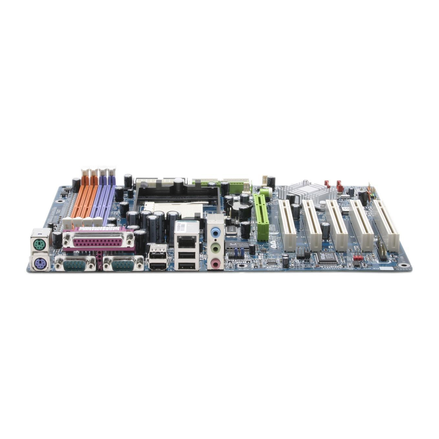
Page 6: Ga-K8U-939 Motherboard Layout
GA-K8U-939 Motherboard Layout MS/KB ATX_12V R_USB CD_IN AUDIO F_AUDIO 8100C CODEC SUR_CEN SMSC LPC47M997-NR SPDIF_IO GAME Socket 939 CPU_FAN CLR_CMOS PCI1 PCI2 PCI3 PCI4 PCI5 F_USB1 - 6 - IDE1 SYS_FAN ULi M1689 SATA1 SATA0 BIOS PWR_LED F_USB2 F_PANEL DDR4... -
Page 7: Block Diagram
Block Diagram CPUCLK+/-(1000MHz) AMD K8 DDR 400/333/266/200MHz DIMM Socket 939 DDR RAM AGP Slot Hyper Transport Bus 4X/8X AGPCLK (66MHz) BIOS 2 Serial ATA ATA33/66/100/133 IDE Channels 5 PCI ULi M1689 PCI Bus LPC BUS Floppy SMSC LPT Port LPC47M997- 8100C COM Port RJ45... - Page 8 - 8 -...
-
Page 9: Chapter 1 Hardware Installation
2. Damage as a result of violating the conditions recommended in the user manual. 3. Damage due to improper installation. 4. Damage due to use of uncertified components. 5. Damage due to use exceeding the permitted parameters. 6. Product determined to be an unofficial Gigabyte product. - 9 - Hardware Installation... -
Page 10: Feature Summary
Supports data transfer rate of up to 150 MB/s Supports a maximum of 2 SATA connections Supported on the Win 2000/XP operating systems BIOS Use of licensed AWARD BIOS Supports Q-Flash GA-K8U-939 Motherboard / Athlon 64 / Athlon 64 X2 Dual-Core processor (K8) (Note 2) - 10 -... -
Page 11: Installation Of The Cpu And Heatsink
(Note 2) To set up an 8 channel audio configuration, you must use Audio Combo Kit (optional device). (Note 3) EasyTune 5 functions may vary depending on different motherboards. Installation of the CPU and Heatsink Before installing the CPU, please comply with the following conditions: Please make sure that the motherboard supports the CPU. -
Page 12: Installation Of The Heatsink
The heat sink may adhere to the CPU as a result of hardening of the heat sink paste. To prevent such an occurrence, it is suggested that either thermal tape rather than heat sink paste be used for heat dissipation or using extreme care when removing the heat sink. GA-K8U-939 Motherboard - 12 -... -
Page 13: Installation Of Memory
Installation of Memory Before installing the memory modules, please comply with the following conditions: Please make sure that the memory used is supported by the motherboard. It is recommended that memory of similar capacity, specifications and brand be used. Before installing or removing memory modules, please make sure that the computer power is switched off to prevent hardware damage. - Page 14 Dual Channel Memory Configuration The GA-K8U-939 supports the Dual Channel Technology. When the Dual Channel Technology is activated, the bandwidth of memory bus will be double the original one. Due to CPU limitation, if you want to operate the Dual Channel Technology, please follow the guidelines below for Dual Channel memory configuration.
-
Page 15: Installation Of Expansion Cards
Installation of Expansion Cards You can install your expansion card by following the steps outlined below: Read the related expansion card's instruction document before install the expansion card into the computer. Remove your computer's chassis cover, screws and slot bracket from the computer. Press the expansion card firmly into expansion slot in motherboard. -
Page 16: I/O Back Panel Introduction
Devices like CD-ROM, walkman etc. can be connected to Line In jack. Line Out Connect the stereo speakers, earphone or front surround speakers to this connector. MIC In Microphone can be connected to MIC In jack. You can use audio software to configure 2-/4-/6-/8-channel audio functioning. GA-K8U-939 Motherboard - 16 -... -
Page 17: Connectors Introduction
Connectors Introduction 1) ATX_12V 2) ATX (Power Connector) 3) CPU_FAN 4) SYS_FAN 5) PWR_FAN 6) FDD 7) IDE1 / IDE2 8) SATA0 / SATA1 9) PWR_LED 10) BAT 11) F_PANEL 12) F_AUDIO 13) CD_IN 14) SUR_CEN 15) SPDIF_IO 16) F_USB1 / F_USB2 17) IR 18) GAME 19) CLR_CMOS... - Page 18 (300W or greater). If a power supply is used that does not provide the required power, the result can lead to an unstable system or a system that is unable to start. GA-K8U-939 Motherboard Pin No. Definition...
- Page 19 3/4/5) CPU_FAN / SYS_FAN / PWR_FAN (Cooler Fan Power Connector) The cooler fan power connector supplies a +12V power voltage via a 3-pin power connector and possesses a foolproof connection design. Most coolers are designed with color-coded power connector wires. A red power connector wire indicates a positive connection and requires a +12V power voltage.
- Page 20 8) SATA0 / SATA1 (Serial ATA Connector) Serial ATA can provide up to 150MB/s transfer rate. Please refer to the BIOS setting for the Serial ATA and install the proper driver in order to work properly. GA-K8U-939 Motherboard IDE1 IDE2 Pin No.
- Page 21 9) PWR_LED PWR_LED is connect with the system power indicator to indicate whether the system is on/off. It will blink when the system enters suspend mode. 10) BAT (Battery) Pin No. Definition MPD+ MPD- MPD- Danger of explosion if battery is incorrectly replaced. Replace only with the same or equivalent type recommended by the manufacturer.
-
Page 22: F_Panel (Front Panel Jumper)
F_PANEL connector according to the pin assignment below. MSG (Message LED/Power/Sleep LED) PW (Power Switch) SPEAK (Speaker Connector) HD (IDE Hard Disk Active LED) RES (Reset Switch) GA-K8U-939 Motherboard Speaker Connector Message LED/ Power Power/ Switch Sleep LED... - Page 23 12) F_AUDIO (Front Audio Panel Connector) If you want to use Front Audio connector, you must remove 5-6, 9-10 Jumper. In order to utilize the front audio header, your chassis must have front audio connector. Also please make sure the pin assignments for the cable are the same as the pin assignments for the front audio header.
- Page 24 SPDIF_IO connector. Check the pin assignment carefully while you connect the SPDIF cable, incorrect connection between the cable and connector will make the device unable to work or even damage it. For optional SPDIF cable, please contact your local dealer. GA-K8U-939 Motherboard Pin No. Definition...
- Page 25 16) F_ USB1 / F_USB2 (Front USB Connector) Be careful with the polarity of the front USB connector. Check the pin assignment carefully while you connect the front USB cable, incorrect connection between the cable and connector will make the device unable to work or even damage it.
- Page 26 19) CLR_CMOS (Clear CMOS) You may clear the CMOS data to its default values by this jumper. To clear CMOS, temporarily short 1-2 pin. Default doesn't include the "Shunter" to prevent from improper use this jumper. GA-K8U-939 Motherboard Pin No. Open: Normal...
- Page 27 - 27 - Hardware Installation...
- Page 28 GA-K8U-939 Motherboard - 28 -...
-
Page 29: Chapter 2 Bios Setup
BIOS needs to be reset to its original settings. If you wish to upgrade to a new BIOS, either GIGABYTE's Q-Flash or @BIOS utility can be used. Q-Flash allows the user to quickly and easily update or backup BIOS without entering the operating system. -
Page 30: The Main Menu
The Main Menu (For example: GA-K8U-939 / BIOS Ver.: F1) Once you enter Award BIOS CMOS Setup Utility, the Main Menu (as figure below) will appear on the screen. Use arrow keys to select among the items and press <Enter> to accept or enter the sub-menu. - Page 31 Load Optimized Defaults Optimized Defaults indicates the value of the system parameters which the system would be in best performance configuration. Set Supervisor Password Change, set, or disable password. It allows you to limit access to the system and Setup, or just to Setup. Set User Password Change, set, or disable password.
-
Page 32: Standard Cmos Features
Number of heads Precomp Write precomp Landing Zone Landing zone Sector Number of sectors If a hard disk has not been installed, select NONE and press <Enter>. GA-K8U-939 Motherboard Standard CMOS Features Thu, Jan 20 2005 22:31:24 [None] [None] [None]... -
Page 33: Extended Memory
Drive A / Drive B The category identifies the types of floppy disk drive A or drive B that has been installed in the computer. None No floppy drive installed. 360K, 5.25" 5.25 inch PC-type standard drive; 360K byte capacity. 1.2M, 5.25"... -
Page 34: Advanced Bios Features
(Default value) System The system will not boot and will not access to Setup page if the correct password is not entered at the prompt. GA-K8U-939 Motherboard Advanced BIOS Features [Press Enter] [Floppy]... -
Page 35: Integrated Peripherals
Integrated Peripherals CMOS Setup Utility-Copyright (C) 1984-2005 Award Software OnChip Audio OnChip SATA OnChip SATA Mode On-Chip Primary IDE On-Chip Secondary IDE IDE DMA transfer access Onboard H/W LAN USB 1.1 Controller USB Keyboard Support USB Mouse Support USB 2.0 Controller OnBoard LAN Boot ROM Onboard Serial Port 1 Onboard Serial Port 2... - Page 36 Enable onboard Serial port 2 and address is 2F8/IRQ3. (Default value) 3E8/IRQ4 Enable onboard Serial port 2 and address is 3E8/IRQ4. 2E8/IRQ3 Enable onboard Serial port 2 and address is 2E8/IRQ3. Disabled Disable onboard Serial port 2. GA-K8U-939 Motherboard - 36 -...
- Page 37 UART Mode Select This item allows you to determine which Infra Red(IR) function of Onboard I/O chip. Normal Set onboard I/O chip UART to normal mode. (Default value) IrDA Set onboard I/O chip UART to IrDA mode. ASKIR Set onboard I/O chip UART to ASKIR mode. UR2 Duplex Mode This feature allows you to seclect IR mode.
-
Page 38: Power Management Setup
Modem Ring Resume An incoming call via modem can awake the system from any suspend state. Disabled Disable Modem Ring Resume function. Enabled Enable Modem Ring Resume function. (Default value) GA-K8U-939 Motherboard Power Management Setup [S1(POS)] [Soft-Off] [Instant-off] [Enabled] [Enabled]... - Page 39 Resume by Alarm You can set "Resume by Alarm" item to enabled and key in Date/Time to power on system. Disabled Disable this function. (Default value) Enabled Enable alarm function to POWER ON system. If RTC Alarm Lead To Power On is Enabled. Date (of Month) Alarm : Everyday, 1~31 Time (hh: mm: ss) Alarm : (0~23) : (0~59) : (0~59)
-
Page 40: Pnp/Pci Configurations
Auto 3,4,5,7,9,10,11,12,14,15 PCI 3 IRQ Assignment Auto 3,4,5,7,9,10,11,12,14,15 PCI 4 IRQ Assignment Auto 3,4,5,7,9,10,11,12,14,15 PCI 5 IRQ Assignment Auto 3,4,5,7,9,10,11,12,14,15 GA-K8U-939 Motherboard PnP/PCI Configurations [Auto] [Auto] [Auto] [Auto] [Auto] +/-/PU/PD: Value F10: Save ESC: Exit F6: Fail-Safe Defaults F7: Optimized Defaults Auto assign IRQ to PCI 1. -
Page 41: Pc Health Status
PC Health Status CMOS Setup Utility-Copyright (C) 1984-2005 Award Software Current CPU Temperature Current System Temperature Vcore DDR25V +3.3V +12V Current CPU FAN Speed Current SYSTEM FAN Speed : Move Enter: Select F5: Previous Values Current CPU/System Temperature Detect CPU/System temperature automatically. Current Voltage(V) Vcore / DDR25V / +3.3V / +12V Detect system's voltage status automatically. -
Page 42: Frequency/Voltage Control
Supply voltage as VCC12 required. (Default value) +5%, +7.5%, +10% Increase voltage range as user selected. AGP OverVoltage Control Auto Supply voltage as AGP required. (Default value) +5%, +7.5%, +10% Increase voltage range as user selected. GA-K8U-939 Motherboard Frequency/Voltage Control [Default] [Enabled] [200MHz] [Auto] [Auto] [Auto]... -
Page 43: Load Fail-Safe Defaults
Load Fail-Safe Defaults CMOS Setup Utility-Copyright (C) 1984-2005 Award Software Standard CMOS Features Advanced BIOS Features Integrated Peripherals Power Management Setup PnP/PCI Configurations PC Health Status Frequency/Voltage Control ESC: Quit F8: Q-Flash Fail-Safe defaults contain the most appropriate values of the system parameters that allow minimum system performance. -
Page 44: Set Supervisor/User Password
Setup Menu. If you select "Setup" at "Password Check" in Advance BIOS Features Menu, you will be prompted only when you try to enter Setup. GA-K8U-939 Motherboard Load Fail-Safe Defaults Load Optimized Defaults... -
Page 45: Save & Exit Setup
2-11 Save & Exit Setup CMOS Setup Utility-Copyright (C) 1984-2005 Award Software Standard CMOS Features Advanced BIOS Features Integrated Peripherals Power Management Setup PnP/PCI Configurations PC Health Status Frequency/Voltage Control ESC: Quit F8: Q-Flash Type "Y" will quit the Setup Utility and save the user setup value to RTC CMOS. Type "N"... - Page 46 GA-K8U-939 Motherboard - 46 -...
-
Page 47: Chapter 3 Drivers Installation
Chapter 3 Drivers Installation Pictures below are shown in Windows XP. Insert the driver CD-title that came with your motherboard into your CD-ROM drive, the driver CD-title will auto start and show the installation guide. If not, please double click the CD-ROM device icon in "My computer", and execute the Setup.exe. -
Page 48: Software Application
Software Application This page displays all the tools that Gigabyte developed and some free software, you can choose anyone you want and press "install" to install them. Software Information This page lists the contents of software and drivers in this CD-title. -
Page 49: Hardware Information
Hardware Information This page lists all device you have for this motherboard. Contact Us Please see the last page for details. K8U939 F1 - 49 - Drivers Installation... - Page 50 GA-K8U-939 Motherboard - 50 -...
-
Page 51: Chapter 4 Appendix
Enters the PC Health setting page Confirmation and Execution button Toggles between Easy and Advance Mode Display panel of CPU frequency Shows the current functions status Log on to GIGABYTE website Display EasyTune 5 Help file Quit or Minimize EasyTune 5 software... -
Page 52: Xpress Recovery Introduction
Once you have completed this step, subsequent access to Xpress Recovery can also function by pressing the F9 key during computer power on. Verifying DMI Pool Data Boot from CD: Xpress Recovery V1.0 (C) Copy Right 2003. GIGABYTE Technology CO. , Ltd. 1. Execute Backup Utility 2. Execute Restore Utility 3. Remove Backup Image 4. - Page 53 Press DEL to enter SETUP / Q-Flash, F9 For Xpress Recovery 08/16/2002-I845GE-6A69YG01C-00 Xpress Recovery V1.0 (C) Copy Right 2003. GIGABYTE Technology CO. , Ltd. If you have already entered Xpress Recovery by booting from the CD-ROM, you can enter Xpress Recovery in the future by pressing the F9 key.
- Page 54 If you wish to remove the need for password entry, please select "Set Password" and under "New Password/Confirm Password", make sure there is no entry and then press "Enter" to remove password requirement. 5. Exit and Restart: Exit and restart your computer. GA-K8U-939 Motherboard - 54 -...
-
Page 55: Flash Bios Method Introduction
Updating BIOS with Q-Flash Utility on Dual BIOS Motherboards. Some of Gigabyte motherboards are equipped with dual BIOS. In the BIOS menu of the motherboards supporting Q-Flash and Dual BIOS, the Q-Flash utility and Dual BIOS utility are combined in the same screen. - Page 56 Action bar: Contains the names of four actions needed to operate the Q-Flash/Dual BIOS utility. Pressing the buttons mentioned on your keyboards to perform these actions. GA-K8U-939 Motherboard Select Language Load Fail-Safe Defaults Load Optimized Defaults...
- Page 57 Using the Q-Flash utility: This section tells you how to update BIOS using the Q-Flash utility. As described in the "Before you begin" section above, you must prepare a floppy disk having the BIOS file for your motherboard and insert it to your computer.
- Page 58 Primary Slave : None Secondary Master : CREATIVEDVD-RM DVD1242E BC101 Secondary Slave : None Press DEL to enter SETUP / Dual BIOS / Q-Flash / F9 For Xpress Recovery 09/23/2003-i875P-6A79BG03C-00 GA-K8U-939 Motherboard Dual BIOS Utility Disable Boot From Main Bios...
-
Page 59: Updating Bios With Q-Flash Utility On Single-Bios Motherboards
Press Y on your keyboard to save and exit. Part Two: Updating BIOS with Q-Flash Utility on Single-BIOS Motherboards. This part guides users of single-BIOS motherboards how to update BIOS using the Q-Flash CMOS Setup Utility-Copyright (C) 1984-2004 Award Software Standard CMOS Features Advanced BIOS Features... - Page 60 After BIOS file is read, you'll see a confirmation dialog box asking you "Are you sure to update BIOS?" Please do not take out the floppy disk when it begins flashing BIOS. GA-K8U-939 Motherboard Q-Flash Utility V1.30 Keep DMI Data...
- Page 61 Press Y button on your keyboard after you are sure to update BIOS. Then it will begin to update BIOS. The progress of updating BIOS will be shown at the same time. Flash Type/Size...SST 49LF003A >>>>>>>>>>>>>>>>>>>... Enter : Run Don't Turn Off Power or Reset System Press any keys to return to the Q-Flash menu when the BIOS updating procedure is completed.
- Page 62 Please search for BIOS unzip file, downloading from internet or any other methods (such as: K8U939.F1). Complete update process following the instruction. GA-K8U-939 Motherboard Utility Fig 2. Installation complete and run @BIOS Click Sart/ Programs/ GIGABYTE/@BIOS Fig 4. Select the desired @BIOS server - 62 -...
- Page 63 III. In method I, if the BIOS file you need cannot be found in @BIOS website for downloading and updating it according to method II. IV. Please note that any interruption during updating will cause system unbooted. server, please go onto Gigabyte's - 63 - Appendix...
-
Page 64: Serial Ata Bios Setting Utility Introduction
Spanning stores data onto a drive until it is full, then proceeds to store files onto the next drive in the array. When any disk member fails, the failure affects the entire array. JBOD is not really a RAID and does not support fault tolerance. GA-K8U-939 Motherboard - 64 -... - Page 65 6) Complete RAID utility installation. More information on steps 4 and 5 is provided. (For more detailed setup information, please visit "Support\ Motherboard\ Technology Guide section" on our website at http:\\www.gigabyte.com.tw to read or download the information you need.) Configuring the ALi RAID BIOS The ALi RAID BIOS setup utility lets you choose the RAID array type and which hard drives you want to make part of the array.
- Page 66 Press Y, and then some necessary information will be written to the drives, which will destroy the original data in the drives. Make sure the data in drives is no longer in use before creating RAID 0. GA-K8U-939 Motherboard www.ali.com.tw SPACE :...
- Page 67 Next, the Array Name input line appears for the user to key in a name for the newly created array. The effective characters for an array name is 0-9, A-Z, a-z, space and underscore. RAID BIOS Setup Utility (c) 2004 ALi Corporation Create RAID 0 Striping for Performance Create RAID 1 Mirroring for Reliability Create JBOD for integrated Capacity...
- Page 68 Duplicate Data from M to m (Y/N) ? Drive Model Channel 1 Master : ST3120026AS Channel 2 Master : ST3120026AS Capacity RAID Array A : RAID Array B : RAID Array C : GA-K8U-939 Motherboard www.ali.com.tw SPACE : Select Moving Cursor Enter : Select & Finish Exit...
- Page 69 After the RAID array has been created successfully, its information shows up at RAID Array List. RAID BIOS Setup Utility (c) 2004 ALi Corporation Create RAID 0 Striping for Performance Create RAID 1 Mirroring for Reliability Create JBOD for integrated Capacity Stripe Size Delete RAID Settings &...
- Page 70 "M" and "m" in Drive Select Menu respectively. Press Y to start the rebuild process and data duplication. The process status bar shows up during the duplication process. After configuration of RAID Array, press ESC to exit ALi RAID BIOS setup utility. GA-K8U-939 Motherboard - 70 -...
-
Page 71: Installing The Raid Drivers
Installing the RAID drivers To install Windows 2000/XP onto a Serial ATA hard disk sucessfully, you need to install required driver for the SATA controller on your motherboard during OS installation. Without the driver, the hard disk may not be recognized during the Windows setup process. -
Page 72: 4- / 6- / 8- Channel Audio Function Introduction
Click the icon to select the function. STEP 3: Click "Speaker Configuration" then click on the left selection bar and select "2CH Speaker" to complete 2 channel audio configuration. GA-K8U-939 Motherboard - 72 -... - Page 73 4 Channel Audio Setup STEP 1: Connect the Front Speakers to "Line Out", the Rear Speakers to "Line In". STEP 2: Following installation of the audio driver, you'll find a Sound Effect icon on the lower right hand taskbar. Click the icon to select the function. STEP 3: Click "Speaker Configuration"...
- Page 74 Click "Speaker Configuration" and select the "UAJ Function". Then click on the left selection bar and select "6CH Speaker" to complete 6 channel audio configuration. GA-K8U-939 Motherboard Line In (Rear Speaker Out) Line Out (Front Speaker Out) Mic In (Center/Subwoofer Speaker Out)
- Page 75 8 Channel Audio Setup (requires Audio Combo Kit, optional device) : Audio Combo Kit includes a Surround-Kit and a SPDIF output cable (an optical and coaxial cable). If you want to set up an 8 channel configuration, you need to use the Surround-Kit.
- Page 76 "UAJ Function" and "Only Surround-Kit". Then click on the left selection bar and select "8CH Speaker" to complete 8 channel audio configuration. Sound Effect Configuration: At the sound effect menu, users can adjust sound option settings as desired. GA-K8U-939 Motherboard - 76 -...
- Page 77 SPDIF Output Device (Optional Device) A "SPDIF output" connector is available on the motherboard. Cable with rear bracket could link to the "SPDIF output" connector (As picture.) For the further linkage to decoder, rear bracket provides coaxial cable and Fiber connecting port Connect the SPDIF output device to the rear bracket of PC, and fix it with screw.
- Page 78 Please connect the devices to the right jacks as above. A window will appear as right picture if you setup the devices properly. Please note that 3D audio function will only appear when 3D audio inputs. GA-K8U-939 Motherboard - 78 -...
- Page 79 If you set wrong with the connectors, the warning message will come out as right picture. Manual setting: If the device picture shows different from what you set, please press "Manual Selection" to set. UAJ Introduction UAJ (Universal Audio Jack) has a very smart feature: It will switch signal automatically when user plugs his audio device to the wrong jack (Line-in/ Line-out).
-
Page 80: Troubleshooting
Below is a collection of general asked questions. To check general asked questions based on a specific motherboard model, please log on to http://www.gigabyte.com.tw Question 1: I cannot see some options that were included in previous BIOS after updating BIOS. Why? Answer: Some advanced options are hidden in new BIOS version. - Page 81 - 81 - Appendix...
- Page 82 GA-K8U-939 Motherboard - 82 -...
- Page 83 - 83 - Appendix...
- Page 84 GA-K8U-939 Motherboard - 84 -...
- Page 85 - 85 - Appendix...
- Page 86 GA-K8U-939 Motherboard - 86 -...
- Page 87 Address: No.6, Bau Chiang Road, Hsin-Tien, Taipei 231, Taiwan TEL: +886-2-8912-4888 FAX: +886-2-8912-4003 Tech. Support : http://tw.giga-byte.com/TechSupport/ServiceCenter.htm Non-Tech. Support(Sales/Marketing) : http://ggts.gigabyte.com.tw/nontech.asp WEB address (English): http://www.gigabyte.com.tw WEB address (Chinese): http://chinese.giga-byte.com U.S.A. G.B.T. INC. TEL: +1-626-854-9338 FAX: +1-626-854-9339 Tech. Support : http://tw.giga-byte.com/TechSupport/ServiceCenter.htm Non-Tech.
- Page 88 China NINGBO G.B.T. TECH. TRADING CO., LTD. Tech. Support : http://tw.giga-byte.com/TechSupport/ServiceCenter.htm Non-Tech. Support(Sales/Marketing) : http://ggts.gigabyte.com.tw/nontech.asp WEB address : http://www.gigabyte.com.cn Shanghai TEL: +86-021-63410999 FAX: +86-021-63410100 Beijing TEL: +86-10-62102838 FAX: +86-10-62102848 Wuhan TEL: +86-27-87851061 FAX: +86-27-87851330 GuangZhou TEL: +86-20-87586074 FAX: +86-20-85517843 Chengdu...
Need help?
Do you have a question about the GA-K8U-939 and is the answer not in the manual?
Questions and answers