Table of Contents

Related Manuals for HORITA VLR-100

Summary of Contents for HORITA VLR-100
- Page 1 HORITA VLR-100 SMPTE VITC/LTC CODE READER LTC GENERATOR LED DISPLAY USER MANUAL For Models VLR-100 and VLR-100PC Doc. 072450-00 Rev. F (C) Copyright 2014 P.O. Box 3993, Mission Viejo, CA 92690 (949) 489-0240 www.horita.com...
- Page 2 No part of this document may be copied or reproduced in any form or by any means without prior written consent of HORITA CO., INC. P.O. Box 3993, Mission Viejo, CA 92690. HORITA CO. INC. makes no warranties with respect to this documentation and disclaims any warranties of merchantability or fitness for a particular purpose.
-
Page 3: Table Of Contents
Connecting LTC In and Out Connecting VITC In and Out Connection Diagrams Figure 4-1, Basic VLR-100 LTC/VITC Reader Connection Figure 4-2, Adding LTC to Source Tape Figure 4-3, Adding LTC to Source Tape Using Jamsync Figure 4-4, Pre-Stripping Tape with Black-Burst and LTC... - Page 5 HORITA TC-TOOLKIT Tape Logging and Control software. The VLR-100 can be factory upgraded to the VLR-100PC. The VLR-100 comes standard as a desktop unit and can be installed in a standard 19" rack using an optional rackmount ear kit, or can be attached to a wall or other piece of equipment using an optional wall mounted swivel bracket kit.
-
Page 7: Smpte Time Code Chapter
Depending upon the playback capabilities of the video recorder, the VLR-100 can read and decode LTC signals at speeds as slow as 1/30th times play speed up to speeds as high as 100 times play speed. - Page 8 numbers progressing from ..28, 29, 00, 01, 02, etc., drop frame time code advances from frame 29 to frame 02, skipping frame numbers 00 and 01, progressing from …28, 29, 02, 03, etc. at the start of each minute. Although drop frame time code is widely used in the broadcast industry, if real time is not an issue it is often avoided elsewhere due to the nature of it’s unconventional numbering system.
-
Page 9: Connecting The Vlr-100 Chapter
4.1 Connecting Power Included with your VLR-100 is an AC power adapter that provides a 9 volt, 500 milliamperes DC output. This adapter is equipped with a miniature phone plug with the "+" (positive) voltage output connected to the front tip of the plug. - Page 10 4.5 Connecting Serial COMM (VLR-100PC Only) The HORITA-supplied serial interface cable connects the VLR-100PC COMM connector (3.5mm phone jack) to a DB-9 male connector compatible with most PC RS-232 serial port interfaces. For a USB connection an RS-232-to-USB adapter cable can be used.
-
Page 11: Operating The Vlr-100 Chapter
Because it takes an entire frame time to read the LTC number, the VLR-100 updates its display value by one frame so that it is always showing the frame number it is reading. This process is known as "on-time updating" and is generally used by all of HORITA's Longitudinal Time Code Reader products to ensure the greatest accuracy. -
Page 12: Generator Run/Stop
-30, -60, -90, or -120 seconds. If the MODE switch is held in its SET position while the VLR-100 is powered up, the automatic backtime preset selection mode is immediately entered. As long as MODE remains in the SET position, the display will sequentially change between 00:00:30:00, 00:01:00:00, 00:01:30:00, and 00:02:00:00, once per second. -
Page 13: Time Code Jamsync
LTC generator presets to the last good time code read, but remains in its STOP mode. If the SELECT switch is in its VITC position when the MODE switch is changed to GEN LTC then the VLR-100 enters the VITC-to-LTC translation, which is described in more detail further on in this manual. -
Page 14: Controlling Direction Of Ltc Output
"run" mode and begins incrementing. On the other hand, if either the translated VITC input was not at play speed or was not available at all, then the VLR-100 does not begin incrementing its time code number and enters its "stop"... -
Page 15: Display Description
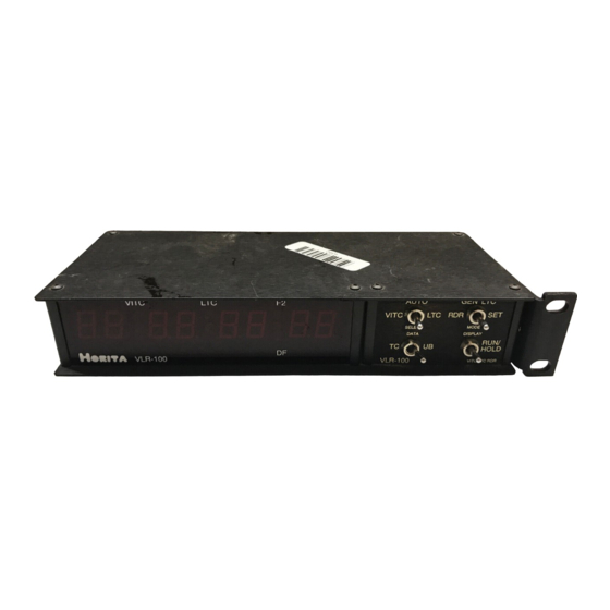
Figure 5-1, VLR-100 LED Display When displaying reader time code data, the VLR-100 automatically shuts off display of the frame digits whenever the tape speed is above two times play speed. (The frames digits can be permanently blanked via the setting of an internal jumper, see Chapter 6.) Four of the discrete LEDs indicate the operating status of the VLR-100 as follows:... -
Page 17: Cleaning
1. Check all cables for opens or shorts. 2. If using an AC power adapter different from the one supplied with the VLR-100, make sure it supplies the VLR-100 with at least 9 volts (maximum of 14 volts) when the VLR-100 is switched on. -
Page 18: Srh Offset Jumper
the shunt installed, both forward and reverse LTC is generated. With the shunt removed, the LTC OUT waveform is always in the forward direction regardless of the apparent tape direction from which the VITC is read. Factory setting allows both forward and reverse LTC generation (shunt installed). SRH OFFSET Jumper The "SRH OFFSET"... - Page 19 SPECIFICATIONS Power Operation 9-to-14V DC, 650 mA max AC Adapter 9 volt, 500 mA Connectors VIDEO IN VIDEO OUT LTC IN LTC OUT COMM 3.5MM mini phone jack (VLR-100PC only) POWER 3.5MM mini phone jack Switches And Controls SELECT Three-position toggle switch DATA Toggle switch MODE...
Need help?
Do you have a question about the VLR-100 and is the answer not in the manual?
Questions and answers