Table of Contents
Advertisement
TABLE OF CONTENTS
1 Safety Precautions----------------------------------------------- 2
2 Specifications ----------------------------------------------------- 4
2.1. CS-C9GKZW CU-2C18GKH --------------------------- 4
2.2. CS-C9GKZW CU-3C20GKH --------------------------- 6
3 Features ------------------------------------------------------------- 8
4 Location of Controls and Components ------------------- 9
4.1. Product Overview------------------------------------------ 9
5 Dimensions--------------------------------------------------------10
5.1. Indoor Unit & Remote Control -------------------------10
5.2. Outdoor Unit ----------------------------------------------- 11
6 Refrigeration Cycle Diagram --------------------------------12
6.1. CS-C9GKZW CU-2C18GKH --------------------------12
6.2. CS-C9GKZW CU-3C20GKH --------------------------13
7 Block Diagram----------------------------------------------------14
7.1. CS-C9GKZW CU-2C18GKH --------------------------14
7.2. CS-C9GKZW CU-3C20GKH --------------------------15
8 Wiring Connection Diagram ---------------------------------16
8.1. CS-C9GKZW CU-2C18GKH --------------------------16
CS-C9GKZW CU-2C18GKH
CS-C9GKZW CU-3C20GKH
PAGE
8.2. CS-C9GKZW CU-3C20GKH -------------------------- 17
9 Electronic Circuit Diagram----------------------------------- 18
10 Printed Circuit Board ------------------------------------------ 19
10.1. Indoor Unit ------------------------------------------------- 19
10.2. Indicator ---------------------------------------------------- 21
10.3. Patrol -------------------------------------------------------- 21
10.4. Outdoor Unit----------------------------------------------- 22
11 Installation Instruction ---------------------------------------- 24
11.1. Select The Best Location ------------------------------ 24
11.2. Indoor Unit ------------------------------------------------- 25
11.3. Outdoor Unit----------------------------------------------- 27
12 Operation and Control ---------------------------------------- 31
12.1. Cooling Operation---------------------------------------- 31
12.2. Soft Dry Operation --------------------------------------- 32
12.3. Automatic Operation ------------------------------------ 33
12.4. Operation Control ---------------------------------------- 34
12.5. Indoor Fan Speed Control ----------------------------- 37
12.6. Outdoor Fan Speed Control --------------------------- 38
© 2007 Panasonic HA Air-Conditioning (M) Sdn. Bhd.
(11969-T). All rights reserved. Unauthorized copying and
distribution is a violation of law.
Order No. MAC0701015C3
Air Conditioner
PAGE
Advertisement
Table of Contents

Related Manuals for Panasonic CS-C9GKZW


Summary of Contents for Panasonic CS-C9GKZW
-
Page 1: Table Of Contents
8 Wiring Connection Diagram ---------------------------------16 12.5. Indoor Fan Speed Control ----------------------------- 37 8.1. CS-C9GKZW CU-2C18GKH --------------------------16 12.6. Outdoor Fan Speed Control --------------------------- 38 © 2007 Panasonic HA Air-Conditioning (M) Sdn. Bhd. (11969-T). All rights reserved. Unauthorized copying and distribution is a violation of law. -
Page 2: Safety Precautions
12.7. Vertical Airflow Direction Control --------------------- 39 14 Troubleshooting Guide --------------------------------------- 50 12.8. Horizontal Airflow Direction Control ----------------- 39 14.1. Refrigeration cycle system ---------------------------- 50 12.9. Powerful Operation -------------------------------------- 39 15 Disassembly and Assembly Instructions -------------- 52 12.10. Quiet Operation------------------------------------------- 40 15.1. - Page 3 12. Ventilate if there is refrigerant gas leakage during operation. It may cause toxic gas when the refrigerant contacts with fire. 1. The equipment must be earthed. It may cause electrical shock if grounding is not perfect. 2. Do not install the unit at place where leakage of flammable gas may occur. In case gas leaks and accumulates at surrounding of the unit, it may cause fire.
-
Page 4: Specifications
2 Specifications 2.1. CS-C9GKZW CU-2C18GKH Item Unit Indoor unit Outdoor unit Performance Test Condition ISO 5151 Capacity (1 Unit) 2.40 - 2.44 (2 Units) 4.80 - 4.88 BTU/h (1 Unit) 8180 - 8320 (2 Units) 16400 - 16600 *kJ/h (1 Unit) 8640 - 8780 (2 Units) 17280 - 17570 (1 Unit) 3.29 - 3.17 (2 Units) 3.29 - 3.17... - Page 5 Item Unit Power Source (Phase, Voltage, Cycle) ø Single Single Input power (1 Unit) 730 (2 Units) 1.46k (1 Unit) 770 (2 Units) 1.54k Starting Current Running Current Cooling (1 Unit) 3.5 (2 Units) 7.0 (1 Unit) 3.3 (2 Units) 6.6 Power Factor Cooling Power factor means total figure of compressor, indoor fan motor and outdoor fan motor.
-
Page 6: Cs-C9Gkzw Cu-3C20Gkh
2.2. CS-C9GKZW CU-3C20GKH Item Unit Indoor unit Outdoor unit Performance Test Condition ISO 5151 Single Operation Single Operation Double Operation Triple Operation (B, A1, A2) (A1 or A2) (A1 + A2) (B + A1 or A2) (B + A1 + A2) Capacity —... - Page 7 1. Cooling capacities are based on indoor temperature of 27°C D.B. (80.6°F D.B.), 19.0°C W.B. (66.2°F W.B.) and outdoor air temperature of 35°C D.B. (95°F D.B.), 24°C W.B. (75.2°F W.B.) Item Unit Indoor unit Outdoor unit Power Source ø Single (Phase, Voltage, Cycle) 240 - 220 Input power...
-
Page 8: Features
3 Features • High Efficiency • Compact Design • Wider range of horizontal discharge air • Air Filter with function to reduce dust and smoke • Automatic air swing and manual adjusted by Remote Control for vertical airflow • Long Installation Piping - long piping up to 15 meter •... -
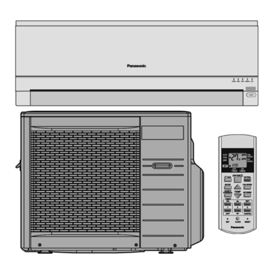
Page 9: Location Of Controls And Components
4 Location of Controls and Components 4.1. Product Overview 4.1.1. Indoor Unit 4.1.2. Outdoor Unit 4.1.3. Remote Control... -
Page 10: Dimensions
5 Dimensions 5.1. Indoor Unit & Remote Control... -
Page 11: Outdoor Unit
5.2. Outdoor Unit 5.2.1. CU-2C18GKH 5.2.2. CU-3C20GKH... -
Page 12: Refrigeration Cycle Diagram
6 Refrigeration Cycle Diagram 6.1. CS-C9GKZW CU-2C18GKH... -
Page 13: Cs-C9Gkzw Cu-3C20Gkh
6.2. CS-C9GKZW CU-3C20GKH... -
Page 14: Block Diagram
7 Block Diagram 7.1. CS-C9GKZW CU-2C18GKH... -
Page 15: Cs-C9Gkzw Cu-3C20Gkh
7.2. CS-C9GKZW CU-3C20GKH... -
Page 16: Wiring Connection Diagram
8 Wiring Connection Diagram 8.1. CS-C9GKZW CU-2C18GKH Resistance of Indoor Fan Motor Windings Resistance of Compressor Windings CONNECTION CWA921181J CONNECTION 2PS132D3AA02 390.0 Ω 4.2 Ω YELLOW-BLUE C - R 394.0 Ω 4.954 Ω YELLOW-RED C - S Resistance of Outdoor Fan Motor Windings... -
Page 17: Cs-C9Gkzw Cu-3C20Gkh
8.2. CS-C9GKZW CU-3C20GKH Resistance of Indoor Fan Motor Windings Resistance of Compressor Windings CONNECTION CWA921181J CONNECTION 2PS132D3AA02 390.0 Ω 4.2 Ω YELLOW-BLUE C - R 394.0 Ω 4.954 Ω YELLOW-RED C - S Resistance of Outdoor Fan Motor Windings CONNECTION 2PS192D3BA02 3.187 Ω... -
Page 18: Electronic Circuit Diagram
9 Electronic Circuit Diagram... -
Page 19: Printed Circuit Board
10 Printed Circuit Board 10.1. Indoor Unit TOP VIEW... - Page 20 BOTTOM VIEW...
-
Page 21: Indicator
10.2. Indicator TOP VIEW BOTTOM VIEW 10.3. Patrol... -
Page 22: Outdoor Unit
10.4. Outdoor Unit 10.4.1. CU-3C20GKH TOP VIEW... - Page 23 BOTTOM VIEW...
-
Page 24: Installation Instruction
11 Installation Instruction 11.1. Select The Best Location Indoor Unit Indoor/Outdoor Unit Installation Diagram • There should not be any heat source or steam near the unit. • There should not be any obstacles blocking the air circulation. • A place where air circulation in the room is good. •... -
Page 25: Indoor Unit
11.2. Indoor Unit 11.2.2. To Drill A Hole In The Wall And Install A Sleeve Of Piping 11.2.1. How To Fix Installation Plate 1. Insert the piping sleeve to the hole. The mounting wall is strong and solid enough to prevent it from 2. - Page 26 For the embedded piping Insert the connecting cable Install the Indoor unit Secure the Indoor Unit Pull out the piping and drain hose How to keep the cover (This can be used for left rear piping & left bottom piping also.)
-
Page 27: Outdoor Unit
• Secure the cable onto the control board with the holder (clamper). • How to pull the piping and drain hose out, in case of the embedded piping. 11.3. Outdoor Unit • In case of left piping how to insert the connecting cable and 11.3.1. - Page 28 • When tightening the flare nut with torque wrench, ensure the direction for tightening follows the arrow on the wrench. CAUTION : The CU-3C20GKH/CS-C9GKZW have different cooling capacities depending on the connection to A and/or B on CU-3C20GKH individually. (Refer to SPECIFICATIONS on CATALOG) 11.3.3.
- Page 29 2) Air purging The air which contains remaining moisture in the refrigeration cycle may cause a malfunction on the compressor. 1. To purge the air, push the pin on the gas side 3-way valve for three seconds using with a hexagonal wrench and set it free for one minute.
- Page 30 Note: Knife switch (Disconnecting means) should have minimum 3.5 mm contact gap. Secure the cable onto the control board with the holder (clamper). 11.3.5. Pipe Insulation 1. Please carry out insulation at pipe connection portion as mentioned in Indoor/Outdoor Unit Installation Diagram. Please wrap the insulated piping end to prevent water from going inside the piping.
-
Page 31: Operation And Control
12 Operation and Control 12.1. Cooling Operation • Cooling operation can be set using remote control. • This operation is applied to cool down the room temperature reaches the setting temperature set on the remote control. • The remote control setting temperature, which takes the reading of intake air temperature sensor, can be adjusted from 16°C to 30°C. -
Page 32: Soft Dry Operation
12.2. Soft Dry Operation • Soft Dry operation can be set using remote control. • Soft Dry operation is applied to dehumidify and to perform a gentle cooling to the room. • This operation starts when the intake air temperature sensor reaches the setting temperature on the remote control. •... -
Page 33: Automatic Operation
12.3. Automatic Operation • Automatic operation can be set using remote control. • This operation starts to operate with indoor fan at SLo speed for 20 seconds to judge the intake air temperature. • After judged the temperature, the operation mode is determined by referring to the below standard. •... -
Page 34: Operation Control
12.4. Operation Control 12.4.1. Restart Control (Time Delay Safety Control) • When the thermo-off temperature (temperature which compressor stops to operate) is reached during:- - Cooling operation - the compressor stops for 3 minutes (minimum) before resume operation. - Soft Dry operation - the compressor stops for 6 minutes (minimum) before resume operation. •... - Page 35 12.4.5. Freeze Preventive Control • To protect indoor heat exchanger from freezing and to prevent higher volume of refrigerant in liquid form return to compressor. • This control will activate when the temperature of indoor heat exchanger falls below 2°C continuously for more than 4 minutes. •...
- Page 36 12.4.7. Dew Prevention control • To prevent dew formation at indoor unit discharge area. • This control will be activated if:- - Cooling mode or Quiet mode. - Remote Control setting temperature is less than 25°C. - Fan speed is at CLo or QLo. - Room temperature is constant (±1°C) for 30 minutes.
-
Page 37: Indoor Fan Speed Control
12.5. Indoor Fan Speed Control • Indoor Fan Speed can be set using remote control. 12.5.1. Fan Speed Rotation Chart Speed Fan Speed (rpm) CS-C9GKZW S Hi 1300 1210 1000 H Lo C Lo S Lo Q Hi 1110 Q Me Q Lo 12.5.2. -
Page 38: Outdoor Fan Speed Control
• Auto Fan Speed during cooling operation: 1. Indoor fan will rotate alternately between off and on as shown in below diagram. 2. At the beginning of each compressor start operation, indoor fan will increase fan speed gradually for deodorizing purpose. 3. -
Page 39: Vertical Airflow Direction Control
12.7. Vertical Airflow Direction Control 12.7.1. Auto Control • When the vertical airflow direction is set to Auto using the remote control, the louver swings up and down as shown in the diagram. • When stop operation using the remote control, the discharge vent is reset, and stop at the closing position. •... -
Page 40: Quiet Operation
12.10. Quiet Operation (For Cooling Operation or cooling region of Soft Dry Operation) • To provide quiet cooling operation condition compare to normal operation. • Once the Quiet Mode is set at the remote control, the Quiet Mode LED illuminated. The sound level will reduce around 2 dB(A) for Lo fan speed or 3 dB(A) for Hi/Me fan speed against the present operation sound level. -
Page 41: Timer Control
12.11. Timer Control 12.11.1. ON Timer • When the ON Timer is set by using the remote control, the unit will start to operate slightly before the set time, so that the room will reach nearly to the set temperature by the set time. •... -
Page 42: Patrol Operation
12.14. Patrol Operation 1. Purpose To monitor air dirtiness level by using gas sensor and activates e-ion operation whenever air is dirty. 2. Control Condition a. Patrol operation start condition • When the unit operation is started with “OFF/ON” button. •... - Page 43 3. Control Content a. Gas Sensor Control • First 2 minutes from Patrol function activates is stabilization time, during stabilization time, no air dirtiness level is monitored. The Air Dirtiness level is set to level 2. • After that, gas sensor starts to record the resistance value at fixed interval. Higher resistance value indicates cleaner air. •...
- Page 44 c. Indoor Fan Control • During any operation mode combines with Patrol operation, fan speed follows respective operation mode. • During Patrol individual operation if e-ion starts, only Auto Fan Speed and no Powerful operation is allowed. Even if “Fan Speed”...
-
Page 45: E-Ion Operation
12.15. e-ion Operation 1. Purpose This operation provides clean air by producing negative ions to attract dust captured at the positively charged e-ion filters. 2. Control Condition a. e-ion operation start condition • During unit running at any operation mode, if “e-ion” button is pressed, combination operation (operation mode + e-ion operation) starts. - Page 46 3. Control Content a. Indoor fan control • During any operation mode combines with e-ion operation, fan speed follows respective operation mode. • During e-ion individual operation - only Auto Fan Speed and no Powerful operation is allowed. Even if Fan Speed button is pressed, no signal is sent to air conditioner, and no change on LCD display.
- Page 47 g. Error Detection Control When e-ion indicator blink, it indicates error listed below: a. e-ion AIR PURIFYING SYSTEM main connector to PCB is open: Judgment Method • During e-ion operation (include during Patrol operation), e-ion AIR PURIFYING SYSTEM main connector to PCB is opened.
-
Page 48: Servicing Mode
13 Servicing Mode 13.1. Auto OFF/ON Button 1. AUTO OPERATION MODE The Auto operation will be activated immediately once the Auto OFF/ON button is pressed. This operation can be use to operate air conditioner with limited function if remote control is misplaced or malfunction. 2. -
Page 49: Remote Control Button
13.3. Remote Control Button 13.3.1. SET BUTTON • To check current remote control transmission code. - Press for more than 10 seconds. • To change the air quality sensor sensitivity: - Press and release with pointer. - Press the Timer Decrement button to select sensitivity: 1. -
Page 50: Troubleshooting Guide
14 Troubleshooting Guide 14.1. Refrigeration cycle system In order to diagnose malfunctions, make sure that there are no electrical problems before inspecting the refrigeration cycle. Such problems include insufficient insulation, problem with the power source, malfunction of a compressor and a fan. The normal outlet air temperature and pressure of the refrigeration cycle depends on various conditions, the standard values for them are shown in the table to the right. - Page 51 14.1.1. Relationship between the condition of the air conditioner and pressure and electric current Cooling Mode Condition of the air conditioner Low Pressure High Pressure Electric current during operation Insufficient refrigerant (gas leakage) Clogged capillary tube or Strainer Short circuit in the indoor unit Heat radiation deficiency of the outdoor unit Inefficient compression...
-
Page 52: Disassembly And Assembly Instructions
15 Disassembly and Assembly Instructions WARNING • Cautions! When handling electronic controller, be careful of electrostatic discharge. • Be sure to return the wiring to its original position. • There are many high voltage components within the heat sink cover so never touch the interior during operation. Wait at least two minutes after power has been turned off. -
Page 54: Indoor Fan Motor And Cross Flow Fan Removal Procedures
15.2. Indoor Fan Motor and Cross Flow Fan Removal Procedures... -
Page 56: Technical Data
16 Technical Data 16.1. Thermostat Characteristics Cooling Soft Dry... -
Page 57: Operation Characteristics
16.2. Operation Characteristics 16.2.1. CS-C9GKZW CU-2C18GKH... - Page 58 16.2.2. CS-C9GKZW CU-3C20GKH...
-
Page 62: Exploded View And Replacement Parts List
17 Exploded View and Replacement Parts List 17.1. Indoor Unit Note: The above exploded view is for the purpose of parts disassembly and replacement. The non-numbered parts are not kept as standard service parts. - Page 63 REF. NO. PART NAME & DESCRIPTION QTY. CS-C9GKZW CHASSY COMPLETE CWD50C1513 FAN MOTOR, AC 15W SINGLE CWA921181J CROSS FLOW FAN COMPLETE CWH02C1045 BEARING ASS’Y CWH64K007 SCREW - CROSS FLOW FAN CWH551146 ION GENERATOR CWH94C0014 EVAPORATOR CO. CWB30C2133 FLARE NUT (1/4)
-
Page 64: Outdoor Unit
17.2. Outdoor Unit 17.2.1. CU-2C18GKH Note: The above exploded view is for the purpose of parts disassembly and replacement. The non-numbered parts are not kept as standard service parts. - Page 65 DESCRIPTION & NAME Q’TY CU-2C18GKH REMARKS BASE PAN ASS’Y CWD50K2166 COMPRESSOR 2PS132D3AA02 ANTI - VIBRATION BUSHING CWH50077 NUT - COMPRESSOR CWH56000J PACKING CWB81043 CONDENSER CWB32C2115 SOUND PROOF BOARD CWH151051 FAN MOTOR BRACKET CWD541056 SCREW FAN MOTOR BRACKET CWH551198 (S.E.ASIA) CWH551060J (MALAYSIA) FAN MOTOR CWA951576...
- Page 66 17.2.2. CU-3C20GKH Note: The above exploded view is for the purpose of parts disassembly and replacement. The non-numbered parts are not kept as standard service parts.
- Page 67 DESCRIPTION & NAME Q’TY CU-3C20GKH REMARKS BASE PAN ASS’Y CWD50K2166 COMPRESSOR 2PS132D3AA02 COMPRESSOR 2PS192D3BA02 ANTI - VIBRATION BUSHING CWH50077 NUT - COMPRESSOR CWH56000J PACKING CWB81043 CONDENSER CWB32C2133 SOUND PROOF BOARD CWH151051 FAN MOTOR BRACKET CWD541056 SCREW FAN MOTOR BRACKET CWD551198 (S.E.ASIA) CWH551060J (MALAYSIA)
Need help?
Do you have a question about the CS-C9GKZW and is the answer not in the manual?
Questions and answers