Table of Contents
Advertisement
Quick Links
Advertisement
Table of Contents

Related Manuals for ERNITEC ELECTRA-T08

Summary of Contents for ERNITEC ELECTRA-T08
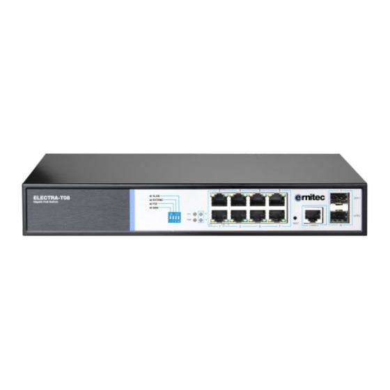
- Page 1 User Manual ELECTRA-T08 8 Port Gigabit Layer 2 PoE Switch...
- Page 2 Agreement The term "switch" mentioned in this manual, unless otherwise specified, refers to 8-port full Gigabit managed PoE switch, hereinafter referred to as ELECTRA-T08 Some pictures for the schematic, the product itself and pictures may be different This icon indicates the items to be cautioned in the operation. If the operation is wrong, the equipment...
-
Page 3: Chapter 1 Product Introduction
Chapter 1 Product Introduction 1.1Product introduction ELECTRA-T08 is managed PoE switch for security transmission and WIFI coverage, meet the WIFI AP, IP-camera, WIFI bridge, IP phones and other types of equipment PoE power supply needs. Products using a new generation of high-performance hardware and software... - Page 4 Front Panel Including indicators, RJ45 port, DIP switch, RST button, SFP port, CONSOLE port, as shown in Figure 1.1 below Indicators ELECTRA-T08 The indicator working status is shown as the following table Indicators Title Color Work status Description Solid...
-
Page 5: Shortcut Button
When the switch mode of operation is CCTV mode, 1-8 port can support 250 meters power supply with 10Mbps speed rate SFP Port ELECTRA-T08 provides 2 Gigabit SFP optical ports (SFP1, SFP2), can be inserted into the Gigabit SFP module RST Button ... -
Page 6: Ground Terminal
Back Panel Including: power socket, power switch, ground terminal Power socket A 100-240VAC 50/60 Hz power receptacle for accommodating the supplied power cord Ground terminal Please use the grounding wire to prevent lightning. To avoid product lightning strikes and extend product life... -
Page 7: Chapter 2 Installation
Chapter 2 Installation 2.1 Installation Precautions Note:To avoid improper use of equipment damage and personal injury, please observe the following precautions Installation safety precautions The power should be kept off during the installation, while wearing anti-static wrist, and to ... -
Page 8: Electromagnetic Interference
Products with this logo are only for safe use in areas below 2000m altitude Dust-proof Dust on the switch surface will cause electrostatic adsorption, poor contact of the metal contacts. Although the device itself has done some measures in anti-static, but when the static electricity exceeds a certain intensity, it will still cause fatal damage to the electronic components on the internal circuit board. -
Page 9: Product Installation
2.2 Product installation Installation method ELECTRA-T08 supports desktop mounting and rack mount.: First, Check rack grounding and stability; Second, Install the two L-brackets in the accessory on each side of the switch panel and secure with the screws provided in the accessory Third, place the switch in an appropriate place in the rack and be supported by the bracket. -
Page 10: Chapter3 Hardware Connection
Chapter3 Hardware connection 3.1RJ45 port connection Connect the RJ45 port of the switch and the corresponding network device via cables, the POE power supply function of the switch is default enabled on the downlink port of the switch, which can be used for IEEE802.3af or IEEE802.3at standards powered devices such as APs, bridges, and network cameras Note:... -
Page 11: Check Before Power On
3.2 SFP Port connection ELECTRA-T08 SFP port only support Gigabit fiber module. Recommended use of standard SFP module products The process of installing a fiber module on a switch is as follows: First, grasp the optic fiber module from the side, insert it smoothly along the SFP port slot until the optic fiber module and switch are in close contact;... -
Page 12: Device Initialization
3.4 Device initialization The switch automatically initializes when the power switch is turned on. Indicator will appear the following situation: After the power is turned on, the power indicator remains on, the other indicator is off at this time; After about 1 second, all lights except for the power light turn on for about 35 seconds and then turn off;... - Page 13 Step4、Enter the default username and password “admin” and then click Login Step5、Entered the switch web management interface successfully when you see picture as below, you can begin to configure the switch...
-
Page 14: Chapter 4 Hardware Specifications
Chapter 4 Hardware Specifications 4.1Hardware Specifications IEEE 802.3: Ethernet Media Access Control (MAC) protocol IEEE 802.3i:10BASE-T Ethernet IEEE 802.3u:100BASE-TX fast Ethernet IEEE 802.3ab:1000BASE-T gigabit Ethernet IEEE 802.3z:1000BASE-X gigabit Ethernet(fiber) IEEE 802.3ad: comply link aggregation standard IEEE 802.3x: flow control Network standard IEEE 802.1p: About the traffic priority of the second layer of Qos / Cos protocol (multicast filtering) IEEE 802.1q:VLAN Bridge operation... - Page 15 One key VLAN One key Exnted(1-8 port 250meters PoE distance) Shortcut function One key Q0S (Video priority) One key AI power supply Support 4K VLAN VLAN Support 802.1Q VLAN、Port VLAN、Voice VLAN Support setting the PoE port priority Support setting PoE power supply period Support setting port power Comply the IEEE 802.1d standard Support MAC address learning and aging automatically...
- Page 16 Support CPU monitor、memory monitoring Support system log Support cable testing Support IGMP v1/v2 Snooping Support static multicast Multicast Support Multicast VLAN 4.2 Features 1-8 port support 250Meters long-distance power supply (recommended cat5e or 6 network cable) Support a key VLAN, the port 1-8 isolated from each other, which can effectively inhibit network ...
Need help?
Do you have a question about the ELECTRA-T08 and is the answer not in the manual?
Questions and answers