Table of Contents
Advertisement
Quick Links
Advertisement
Table of Contents

Subscribe to Our Youtube Channel
Related Manuals for Repotec GEPOESM-ESW26K Series


Summary of Contents for Repotec GEPOESM-ESW26K Series
- Page 1 26-Port L2 PoE Plus Managed Switch Installation and Getting Started Guide...
- Page 2 INSTALLATION and GETTING STARTE GUIDE 26-Port L2 PoE Plus Managed Switch Installation and Getting Started Guide 2012, Manufacture Corporation. All rights reserved. All brand and product names are trademarks or registered trademarks of their respective companies Publication date: Oct., 2012 Revision A3...
-
Page 3: About This Guide
ABOUT THIS GUIDE PURPOSE This guide gives specific information on how to operate and use the management functions of the switch. AUDIENCE The guide is intended for use by network administrators who are responsible for operating and maintaining network equipment; consequently, it assumes a basic working knowledge of general switch functions, the Internet Protocol (IP), and Simple Network Management Protocol (SNMP). -
Page 4: Compliances And Safety Statements
COMPLIANCES AND SAFETY STATEMENTS FCC-CLASS A This equipment has been tested and found to comply with the limits for a Class A computing device pursuant to Subpart J of part 15 of FCC Rules, which are designed to provide reasonable protection against such interference when operated in a commercial environment. - Page 5 EMC: EN55022(2006)+A1:2007/CISPR Class A 22:2006+A1:2006 4K V CD, 8KV, AD IEC61000-4-2 (2001) 3V/m IEC61000-4-3( 2002) 1KV – (power line), 0.5KV – (signal line) IEC61000-4-4(2004) Line to Line: 1KV, Line to Earth: 2KV IEC61000-4-5 (2001) 130dBuV(3V) Level 2 IEC61000-4-6 (2003) 1A/m IEC61000-4-8 (2001) Voltage dips: >95%, 0.5period, 30%, 25periods...
- Page 6 The switch is indoor device; if it will be used in outdoor environment or connects with some outdoor device, then it must use a lightning arrester to protect the switch ARNING Self-demolition on Product is strictly prohibited. Damage caused by self-demolition will be charged for repairing fees. Do not place product at outdoor or sandstorm.
-
Page 7: Table Of Contents
Contents ABOUT THIS GUIDE ..........................ii COMPLIANCES AND SAFETY STATEMENTS ................... iii INTRODUCTION ............................. 1 OVERVIEW ............................1 DESCRIPTION OF HARDWARE ......................4 NETWORK PLANNING .......................... 6 INTRODUCTION TO SWITCHING ..................... 6 APPLICATION EXAMPLES ....................... 6 INSTALLING THE SWITCH ........................9 SELECTING A SITE ........................... - Page 8 IN-BAND ACCESS ........................... 28 CABLES ..............................29 TWISTED-PAIR CABLE AND PIN ASSIGNMENTS ............... 29 STRAIGHT- THROUGH WIRING ..................... 30 1000BASE-T PIN ASSIGNMENTS ....................31 CABLE TESTING FOR EXISTING CATEGORY 5 CABLE ............. 31 FIBER STANDARDS ........................32 SPECIFICATIONS ..........................33 PHYSICAL CHARACTERISTICS .....................
-
Page 9: Introduction
Networking includes Small Business or enterprise application and helps you create a more efficient, better-connected workforce. The GEPOESM-ESW26K Series 26-Ports Switch is broad portfolio of easy-implement managed Ethernet switches. Models include with 26-port of Gigabit Ethernet connectivity,... - Page 10 Back of the Switches GEPoESM-ESW26/GEPoESM-ESW26K Publication date: Oct., 2012 Revision A3...
- Page 11 SWITCH The switch performs a wire-speed, non-blocking switching fabric. ARCHITECTURE This allows wire-speed transport of multiple packets at low latency on all ports simultaneously. The switch also features full-duplex capability on all ports, which effectively doubles the bandwidth of each connection. This switch uses store-and-forward technology to ensure maximum data integrity.
-
Page 12: Description Of Hardware
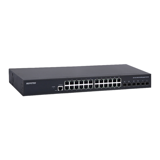
DESCRIPTION OF HARDWARE The switch contains 24 1000BASE-T RJ-45 ports. All RJ-45 ports 1000BASE-T support automatic MDI/MDI-X operation, auto-negotiation and PORTS IEEE 802.3x auto-negotiation of flow control, so the optimum data rate and transmission can be selected automatically. GEPOESM-ESW26K supports the Small Form Factor Pluggable TRANSCEIVER (SFP) transceiver slots are shared with RJ-45 port 25 to 26. - Page 13 PORT AND The GEPOESM-ESW26K Series switch includes a display panel for system and port indications that simplify installation and SYSTEM STATUS network troubleshooting. The LEDs, which are located on left LEDS hand side of the front panel for easy viewing. Details are shown below and described in the following tables.
-
Page 14: Network Planning
NETWORK PLANNING INTRODUCTION A network switch allows simultaneous transmission of multiple TO SWITCHING packets; it can partition a network more efficiently than bridges or routers. Therefore the switch has been recognized as one of the most important devices for today’s networking technology. When performance bottlenecks are caused by congestion at the network access point such as file server, the device can be connected directly to a switched port. - Page 15 Figure 4: Network Connection between Remote Site and Central Site GEL2-ESW12 GEPoESM-ESW26 GEL2-ESW08 GEL2-ESW10 Figure 5: Peer-to-peer Network Connection GEPOESM-ESW26 Publication date: Oct., 2012 Revision A3...
- Page 16 Figure 6: Office Network Connection GELPoE2-ESW26/ GEL2-ESW10 GEL2-ESW08 Publication date: Oct., 2012 Revision A3...
-
Page 17: Installing The Switch
INSTALLING THE SWITCH SELECTING A The Switch can be mounted in a standard 19-inch equipment SITE rack (Via Optional Rack mount Kit) or on a flat surface. Be sure to follow the guidelines below when choosing a location. ◆ The site should: Be at the center of all the devices you want to link and ... -
Page 18: Equipment Checklist
Figure 7: RJ-45 Connections Figure 8: SFP Transceiver EQUIPMENT After unpacking this switch, please check the contents to be sure CHECKLIST you have received all the components. Then, before beginning the installation, be sure you have all other necessary installation equipment. - Page 19 Circuit Overloading: Be sure that the supply circuit to the rack assembly is not overloaded. Grounding: Rack-mounted equipment should be properly grounded. TO Rack-mount Devices: Step1. Attach the brackets to the device using the screws provided in the Mounting Accessory.
- Page 20 Step3. If installing a single switch only, turn to “Connection to a Power Source” at the end of this chapter. Step4. If installing multiple switches, mount them in the rack, one below the other, in any order. Publication date: Oct., 2012 Revision A3...
-
Page 21: Installing An Optional Sfp Transceiver
DESKTOP OR SHELF MOUNTING: Step1. Attach the four adhesive rubber feet to the bottom of the first switch. Figure 11: Attaching the Adhesive Rubber Feet Step2. Set the device on a flat surface near an AC power source, making sure there are at least two inches of space on all sides for proper air flow. - Page 22 install or remove a mini-GBIC. Use only supported genuine Manufacture mini-GBICs AUTION with your switch. Non-Manufacture mini-GBIC might have compatible issue, and their use may result in product malfunction. Publication date: Oct., 2012 Revision A3...
- Page 23 Figure 12: Inserting an SFP Transceiver into a Slot The SFP slots support the following optional SFP transceivers: Model Name Description SFP.LC 1000Base-SX GE SFP Fiber Module, LC Multi-Mode 850nm SFP.LC.M2 1000Base-SX GE SFP Fiber Module, LC Multi-Mode 1310nm 2km SFP.LC.S10 1000Base-LX GE SFP Fiber Module, LC Single-Mode 10km SFP.LC.S30...
-
Page 24: Connecting To A Power Source
Step3. Slide the SFP transceiver into the slot until it clicks into place. SFP transceivers are not provided in the switch package. CONNECTING You can plug or remove power cord from AC power socket , to TO A POWER switch the power on and off . SOURCE Figure 13: Inserting the Power Cord to AC Power Socket Step1. - Page 25 Figure 14: Serial Port (RJ-45) Pin-Out 2 TXD 5 GND 3 RXD WIRING MAP FOR SERIAL CABLE Table 4: Serial Cable Wiring Switch’s 8-Pin Serial Port Null Modem PC’s 9-Pin DTE Port 2 RXD (receive data) 3 TXD (transmit data) ----------------- 3 RXD (receive data) -----------------...
-
Page 26: Operation Of Web-Based Management
Operation of Web-based Management The default values of the managed switch are listed in the table below: IP Address 192.168.1.1 255.255.255.0 Subnet Mask Default 192.168.1.254 Username admin Password After the managed switch has been finished configuration in the CLI via the switch’s serial interface, you can browse it. - Page 27 If you need to configuration the function or parameter then you can refer the detail in the User Guide. Or you could access to the Switch and click the "help" under the web GUI and the switch will pop-up the simple help content to teach you how to set the parameters.
-
Page 28: Making Network Connections
MAKING NETWORK CONNECTIONS CONNECTING The switch is designed to be connected to 10, 100 or 1000Mbps network cards in PCs and servers, as well as NETWORK to other switches and hubs. It may also be connected to DEVICES remote devices using optional SFP transceivers. TWISTED-PAIR Each device requires an unshielded twisted-pair (UTP) cable with RJ-45 connectors at both ends. - Page 29 Step2. If the device is a network card and the switch is in the wiring closet, attach the other end of the cable segment to a modular wall outlet that is connected to the wiring closet. (See the section “Network Wiring Connections.”) Otherwise, attach the other end to an available port on the switch.
-
Page 30: Fiber Optic Sfp Devices
FIBER OPTIC An optional Gigabit SFP transceiver can be used for a backbone connection between switches, SFP DEVICES connecting to a high-speed server. Each single-mode fiber port requires 9/125 micron single-mode fiber optic cable with an LC connector at both ends. Each multimode fiber optic port requires 50/125 or 62.5/125 micron multimode fiber optic cabling with an LC connector at both ends. - Page 31 CONNECTIVITY RULES When adding hubs to your network, please note that because switches break up the path for connected devices into separate collision domains, you should not include the switch or connected cabling in your calculations for cascade length involving other devices.
- Page 32 100 MBPS FAST ETHERNET COLLISION DOMAIN Table 9: Maximum Fast Ethernet Cable Lengths Cable Type Maximum Cable Length Connector Category 5, 5e or 6 100-ohm 100.m (328 ft) RJ-45 UTP or STP Publication date: Oct., 2012 Revision A3...
-
Page 33: Cable Labeling And Connection Records
CABLE LABELING AND CONNECTION RECORDS When planning a network installation, it is essential to label the opposing ends of cables and to record where each cable is connected. This will allow user to easily locate inter-connected devices, isolate faults and change your topology without need for unnecessary time consumption. -
Page 34: Troubleshooting
TROUBLESHOOTING Basic Most problems are caused by the following situations. Check these items first when starting your Troubleshooting troubleshooting: Tips Connecting to devices that have a fixed full- duplex configuration. The RJ-45 ports are configured as “Auto”. That is, when connecting to attach devices, the switch will operate in one of two ways to determine the link speed and the communication mode (half duplex or full duplex):... - Page 35 Check the port A port on your Switch may not be operating as you expect configuration. because it has been put into a “ blocking” state by Spanning Tree, GVRP (automatic VLANs), or LACP (automatic trunking). (Note that the normal operation of the Spanning Tree, GVRP, and LACP features may put the port in a blocking state.) Or, the port just may have been configured as disabled through software.
-
Page 36: Power And Cooling Problems
POWER AND COOLING PROBLEMS Installation If the power indicator does not turn on when the power cord is plugged in, you may have a problem with the power outlet, power cord, or internal power supply. However, if the unit powers off after running for a while, check for loose power connections, power losses or surges at the power outlet. -
Page 37: Cables
CABLES TWISTED-PAIR For 10/100BASE-TX connections, the twisted-pair cable must CABLE AND PIN have two pairs of wires. For 1000BASE-T connections the twisted-pair cable must have four pairs of wires. Each wire pair is ASSIGNMENTS identified by two different colors. For example, one wire might be green and the other, green with white stripes. -
Page 38: Straight- Through Wiring
4, 5, 7, 8 Not used Not used The “+” and “-” signs represent the polarity of the wires that make up each wire pair. STRAIGHT- If the twisted-pair cable is to join two ports and only one of the ports has an internal crossover (MDI-X), the two pairs of wires THROUGH must be straight-through. -
Page 39: 1000Base-T Pin Assignments
1000BASE-T PIN All 1000BASE-T ports support automatic MDI/MDI-X operation, so you can use straight-through cables for all network ASSIGNMENTS connections to PCs or servers, or to other switches or hubs. The table below shows the 1000BASE-T MDI and MDI-X port pinouts. -
Page 40: Fiber Standards
FIBER The International Telecommunication Union (ITU-T) standardized various fiber types for data networks. These are STANDARDS summarized in the following table. Table 13: Fiber Standards ITU-T Standard Description Application Multimode Fiber Short-reach connections in the 1300- nm G.651 or 850-nm band 50/125-micron core Non-Dispersion-Shifted Fiber G.652... -
Page 41: Specifications
44(H) x 442(W) x 300(D)mm (For PoE 185W) 44(H) x 442(W) x 385(D)mm (For PoE 370W) TEMPERATURE Operating: 0°C to 40°C (32°F to 104°F) HUMIDITY Operating: 10% to 90% (non-condensing) POWER INPUT For GEPOESM-ESW26/ GEPOESM-ESW26K series: 100~240VAC, 50~60Hz Publication date: Oct., 2012 Revision A3... -
Page 42: Switch Features
POWER SUPPLY For GEPOESM-ESW26/ GEPOESM-ESW26K series: Internal: 1. 250 Watt (For PoE 185W) 2. 525 Watt (For PoE 370W) POWER 1.185 Watts maximum for PoE CONSUMPTION 2. 370 Watts maximum for PoE SWITCH FEATURES FORWARDING Store-and-forward MODE THROUGHPUT 95.232 Mpps FLOW CONTROL Full Duplex: IEEE 802.3x... -
Page 43: Compliances
COMPLIANCES EMISSIONS EN55022 (CISPR 22) Class A EN 61000-3 FCC Class A CE Mark IMMUNITY EN 61000-4-2/3/4/5/6/8/11 EN 55024 Publication date: Oct., 2012 Revision A3... -
Page 44: Compliances
COMPLIANCES 10BASE-T IEEE 802.3 specification for 10 Mbps Ethernet over two pairs of Category 3, 4, or 5 UTP cable 100BASE-TX IEEE 802.3u specification for 100 Mbps Ethernet over two pairs of Category 5 UTP cable 1000BASE-LH Specification for long-haul Gigabit Ethernet over two strands of 9/125 micron core fiber cable 1000BASE-LX IEEE 802.3z specification for Gigabit Ethernet over two strands... - Page 45 FULL DUPLEX Transmission method that allows two network devices to transmit and receive concurrently, effectively doubling the bandwidth of that link GIGABIT ETHERNET A 1000 Mbps network communication system based on Ethernet and the CSMA/ CD access method. IEEE Institute of Electrical and Electronic Engineers. IEEE 802.3 Defines carrier sense multiple access with collision detection (CSMA/CD) access method and physical layer specifications.
- Page 46 SWITCHED PORTS Ports that are on separate collision domains or LAN segments. Telecommunications Industry Association. TRANSMISSION Protocol suite that includes TCP as the primary transport CONTROL protocol, and IP as the network layer protocol. PROTOCOL/INTERNE T PROTOCOL (TCP/IP) USER DATAGRAM UDP provides a datagram mode for the packet-switched PROTOCOL (UDP) communications.
Need help?
Do you have a question about the GEPOESM-ESW26K Series and is the answer not in the manual?
Questions and answers