
Subscribe to Our Youtube Channel
Related Manuals for Spectra MI950


Summary of Contents for Spectra MI950
- Page 1 MI950 LGA775 Core 2 Duo Intel Q45 Chipset ® Mini-ITX Motherboard USER’S MANUAL Version 1.0...
- Page 2 Acknowledgments Award is a registered trademark of Award Software International, Inc. PS/2 is a trademark of International Business Machines Corporation. Intel is a trademark or registered trademark of Intel Corporation. Microsoft Windows is a registered trademark of Microsoft Corporation. Winbond is a registered trademark of Winbond Electronics Corporation.
-
Page 3: Table Of Contents
Installations ............5 Installing the CPU ............... 6 ATX Power Installation ............6 Installing the Memory ............7 Setting the Jumpers ............. 8 Connectors on MI950............11 BIOS Setup ............19 Drivers Installation ........41 Intel Chipset Software Installation Utility......42 Intel Graphics Driver Installation........44 Realtek HD Code Audio Driver Installation ..... - Page 4 This page is intentionally left blank. MI950 User’s Manual...
-
Page 5: Introduction
INTRODUCTION Introduction Checklist Your MI950 Core 2 Duo motherboard package should include the items listed below: The MI950 motherboard This User’s manual 1 x I/O shield 1 x serial port cable 2 x SATA cable ... -
Page 6: Product Description
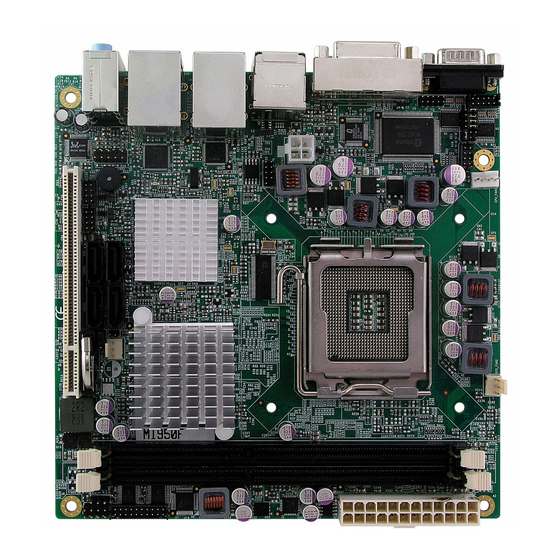
INSTALLATIONS Product Description The MI950 Mini-ITX motherboard is designed for either the Intel Core2 Duo or Core2 Quad processors of up to 1333MHz FSB. It is based on the Intel’s Q45 Express chipset and it comes with two single-channel DDR3 memory slots and 8GB memory capacity for faster system responsiveness and support of 64-bit computing. -
Page 7: Specifications
2x10 pins pin-header for COM3, COM4 2x5 pins pin-header x1 for Digital IO Watchdog Timer Yes (256 segments, 0, 1, 2…255 sec/min) System Voltage +5V, +3.3V, +12V, -12V, 5VSB (2A) Other LAN Wakeup, RAID RoHS Board Size 170mm x 170mm MI950 User’s Manual... -
Page 8: Board Dimensions
INSTALLATIONS Board Dimensions MI950 User’s Manual... -
Page 9: Installations
INSTALLATIONS Installations This section provides information on how to use the jumpers and connectors on the MI950 in order to set up a workable system. The topics covered are: Installing the CPU ................. 6 ATX Power Installation................. 6 Installing the Memory ................7 Setting the Jumpers................ -
Page 10: Installing The Cpu
INSTALLATIONS Installing the CPU The MI950 motherboard supports an LGA 775 processor socket for Intel® Core 2 Duo processors. The LGA 775 processor socket comes with a lever to secure the processor. Refer to the pictures below, from left to right, on how to place the processor into the CPU socket. -
Page 11: Installing The Memory
INSTALLATIONS Installing the Memory The MI950 motherboard supports two DDR3 memory sockets for a maximum total memory of 8GB. It supports DDR3 800/1066MHz. Basically, the system memory interface has the following features: Supports two 64-bit wide DDR data channels Available bandwidth up to 6.4GB/s (DDR3 1066) for two-channel mode. -
Page 12: Setting The Jumpers
The following lists the connectors and their respective functions. Jumper Locations on MI950/MI950F/MI950AF........9 JP4: ME (Management Engine) – Disabled / pin closed ..... 10 JP5: Clear CMOS Contents ..............10 JP1, JP2, JP3: RS232/422/485 (COM2) Selection ...... - Page 13 INSTALLATIONS Jumper Locations on MI950/MI950F/MI950AF Jumper Locations on MI950/MI950F/MI950AF ........9 JP4: ME (Management Engine) – Disabled / pin closed ..... 10 JP5: Clear CMOS Contents ..............10 JP1, JP2, JP3: RS232/422/485 (COM2) Selection ......10 MI950 User’s Manual...
- Page 14 COM2 is selectable for RS232, RS-422 and RS-485. COM2 RS-232 RS-422 RS-485 Function JP1: JP1: JP1: Jumper Setting JP2: JP2: JP2: (pin closed) 3-5 & 4-6 1-3 & 2-4 1-3 & 2-4 JP3: JP3: JP3: 3-5 & 4-6 1-3 & 2-4 1-3 & 2-4 MI950 User’s Manual...
-
Page 15: Connectors On Mi950
INSTALLATIONS Connectors on MI950 The connectors on MI950 allows you to connect external devices such as keyboard, floppy disk drives, hard disk drives, printers, etc. The following table lists the connectors on MI950 and their respective functions. ATX2: 24-pin ATX Power Connector ..........13 ATX1: ATX 12V Power Connector............ - Page 16 INSTALLATIONS Connector Locations on MI950/MI950F/MI950RF ATX2: 24-pin ATX Power Connector ....................13 ATX1: ATX 12V Power Connector .......................13 DDRIII1: Channel A DDR3 Socket .......................13 DDRIII2: Channel B DDR3 Socket .......................13 CPU_FAN1: CPU Fan Power Connector....................13 SYS_FAN1: system Fan1 Power Connector..................13 SYS_FAN2: System Fan2 Power Connector ..................14 CN1: Serial Ports(COM1) ........................14...
-
Page 17: Atx2: 24-Pin Atx Power Connector
DDRIII1: Channel A DDR3 Socket DDRIII2: Channel B DDR3 Socket CPU_FAN1: CPU Fan Power Connector Pin # Signal Name Ground +12V Rotation detection Control SYS_FAN1: system Fan1 Power Connector Pin # Signal Name Ground +12V Rotation detection MI950 User’s Manual... -
Page 18: Sys_Fan2: System Fan2 Power Connector
CTS, Clear to send DTR, Data terminal ready RI, Ring indicator GND, ground Not Used J2: COM2 is jumper selectable for RS-232, RS-422 and RS-485. Pin # Signal Name RS-232 R2-422 RS-485 DATA- DATA+ Ground Ground Ground MI950 User’s Manual... -
Page 19: Cn2: Dvi+Crt Connector
J1: Digital I/O Connector (4 in, 4 out) This 10-pin digital I/O connector supports TTL levels and is used to control external devices requiring ON/OFF circuitry. Signal Name Pin # Pin # Signal Name Ground Out3 Out1 Out2 Out0 MI950 User’s Manual... -
Page 20: J3: Keyboard & Mouse Connector (Testing Use Only)
This 2-pin connector is an “ATX Power Supply On/Off Switch” on the system that connects to the power switch on the case. When pressed, the power switch will force the system to power on. When pressed again, it will force the system to power off. MI950 User’s Manual... -
Page 21: J10: Com3, Com4 Serial Port (Df11 Connector)
Request to send Receive data CTS1 TXD1 Clear to send Transmit data DTR1 Ringing indicator Data terminal ready Not used Ground DSR2 DCD2 RTS2 RXD2 CTS2 TXD2 DTR2 Not used Ground PCI1: PCI Slot (supports two masters) MI950 User’s Manual... - Page 22 INSTALLATIONS This page is intentionally left blank. MI950 User’s Manual...
-
Page 23: Bios Setup
PC Health Status................37 Frequency/Voltage Control ............38 Load Fail-Safe Defaults..............39 Load Optimized Defaults ............. 39 Set Supervisor/User Password............39 Save & Exit Setup ................ 39 Exit Without Saving ..............39 2nd SuperIO Device ..............42 MI950 User’s Manual... -
Page 24: Bios Introduction
<PgUp> and <PgDn> keys to change entries, <F1> for help and <Esc> to quit. When you enter the Setup utility, the Main Menu screen will appear on the screen. The Main Menu allows you to select from various setup functions and exit choices. MI950 User’s Manual... - Page 25 These defaults have been carefully chosen by both Award and your system manufacturer to provide the absolute maximum performance and reliability. Changing the defaults could cause the system to become unstable and crash in some cases. MI950 User’s Manual...
-
Page 26: Standard Cmos Setup
The following describes each item of this menu. Date The date format is: Day : Sun to Sat Month : 1 to 12 Date : 1 to 31 Year : 1999 to 2099 MI950 User’s Manual... - Page 27 +/- keys to set the current time. IDE Channel Master/Slave MI950 with ICH10DO supports 4 Serial ATA connectors The onboard Serial ATA connectors provide Primary and Secondary channels for connecting up to four Serial ATA hard disks . Each channel can support up to two hard disks;...
- Page 28 The system boot will not be halted for a disk error; it will stop for all other errors. All, But Disk/Key The system boot will not be halted for a key- board or disk error; it will stop for all others. MI950 User’s Manual...
-
Page 29: Advanced Bios Features
Quick Power On Self Test When enabled, this field speeds up the Power On Self Test (POST) after the system is turned on. If it is set to Enabled, BIOS will skip some items. MI950 User’s Manual... - Page 30 Password every time you boot up. When you select Setup, the system always boots up and prompts for the Supervisor Password only when the Setup utility is called up. APIC Mode APIC stands for Advanced Programmable Interrupt Controller. The default setting is Enabled. MI950 User’s Manual...
- Page 31 The default setting is Disabled. Baud Rate This configuration is supported only with MI950AF (with iAMT function). The default setting is 19200. Agent after boot This configuration is supported only with MI950AF (with iAMT function). The default setting is Enabled. MI950 User’s Manual...
-
Page 32: Advanced Chipset Features
ISA cards. This memory must be mapped into the memory space below 16 MB. The choices are Enabled and Disabled. PCI Express Root Port Func Press Enter to configure this field. Disable MCHBAR MMIO By default, this feature is enabled. MI950 User’s Manual... - Page 33 This configuration is supported only with MI950AF (with iAMT function). VGA Setting The fields under the On-Chip VGA Setting and their default settings are: PEG/On Chip VGA Control: Auto On-Chip Frame Buffer Size: 32MB DVMT Mode: Enabled DVMT/FIXED memory Size: 256MB PAVP Mode: Lite MI950 User’s Manual...
-
Page 34: Integrated Peripherals
PWRON After PWR-Fail Phoenix - AwardBIOS CMOS Setup Utility Super IO Device 220h ITEM HELP Onboard Serial Port 3 IRQ5 Menu Level > Serial Port 3 Use IRQ 228h Onboard Serial Port 4 IRQ7 Serial Port 4 Use IRQ MI950 User’s Manual... - Page 35 SATA performance with native command queuing & native hot plug. Select [RAID] to use SATA as RAID function. RAID function is supported on the board if it uses ICH10DO. (MI950 supports 4 x SATA with RAID.) MI950 User’s Manual...
- Page 36 Enabled. In order to use USB 2.0, necessary OS drivers must be installed first. Please update your system to Windows 2000 SP4 or Windows XP SP2. USB Keyboard/Mouse/Storage Function The options for this field are Enabled and Disabled. By default, this field is set to Enabled. MI950 User’s Manual...
-
Page 37: Power Management Setup
ACPI Function Enable this function to support ACPI (Advance Configuration and Power Interface). ACPI Suspend The default setting of the ACPI Suspend mode is S1(POS). RUN VGABIOS if S3 Resume The default setting of this field is Auto. MI950 User’s Manual... - Page 38 In the Delay 4 Sec mode, the system powers off when the power button is pressed for more than four seconds or enters the suspend mode when pressed for less than 4 seconds. MI950 User’s Manual...
- Page 39 CPU's RDTSC instruction. HPET is not supported in Windows XP, Windows Server 2003, or earlier Windows versions. HPET is supported under Linux and Windows Vista. By default, this field is enabled. HPET Mode By default, this field is set to 32-bit mode. MI950 User’s Manual...
-
Page 40: Pnp/Pci Configurations
MPEG ISA/VESA VGA card. When this field is disabled, a PCI/VGA cannot work with an MPEG ISA/VESA card. Maximum Payload Size The default setting of the PCI Express Maximum Payload Size is 128. MI950 User’s Manual... -
Page 41: Pc Health Status
This function can help prevent damage to the system that is caused by overheating. Temperatures/Fan Speeds/Voltages These fields are the parameters of the hardware monitoring function feature of the board. The values are read-only values as monitored by the system and show the PC health status. MI950 User’s Manual... -
Page 42: Frequency/Voltage Control
This field enables or disables the auto detection of the PCI clock. Spread Spectrum This field sets the value of the spread spectrum. The default setting is Disabled. This field is for CE testing use only CPU Host/SRC/PCI Clock This field is set as Default. MI950 User’s Manual... -
Page 43: Load Fail-Safe Defaults
Select this option to exit the Setup utility without saving the changes you have made in this session. Typing “Y” will quit the Setup utility without saving the modifications. Typing “N” will return you to Setup utility. MI950 User’s Manual... - Page 44 BIOS SETUP This page is intentionally left blank. MI950 User’s Manual...
-
Page 45: Drivers Installation
Intel Management Engine Interface............. 52 Intel Active Management Technology ..........54 IMPORTANT NOTE: After installing your Windows operating system (Windows 2000/XP/Vista), you must install first the Intel Chipset Software Installation Utility before proceeding with the drivers installation. MI950 User’s Manual... -
Page 46: Intel Chipset Software Installation Utility
Windows 2000/XP/Vista. (Before installing this utility, please update your system to Windows 2000 SP4 or Windows XP SP2) 1. Insert the drivers DVD into the DVD drive. Click Intel and then Intel(R) Q45 Chipset Drivers. Click Intel(R) Chipset Software Installation Utility. MI950 User’s Manual... - Page 47 3. On the Readme Information screen, click Next to continue. When the Setup Progress screen appears, click Next to continue. 4. Setup process is now complete. Click Finish to restart the computer. MI950 User’s Manual...
-
Page 48: Intel Graphics Driver Installation
Intel(R) Q45 Chipset Drivers. Click Intel(R) Q45 Chipset Family Graphics Driver. 2. When the Welcome screen appears, click Next to continue. Click Yes to accept the software license agreement and proceed with the installation process. 3. On the Readme Information screen, click Next to continue. MI950 User’s Manual... - Page 49 DRIVERS INSTALLATION 4. When the Setup Progress screen appears, click Next to continue. 5. Setup is complete. Click Finish to restart the computer. MI950 User’s Manual...
-
Page 50: Realtek Hd Code Audio Driver Installation
Follow the steps below to install the Realtek High Definition Codec Audio Driver. 1. Insert the drivers DVD into the DVD drive. Click Intel and then Intel(R) Q45 Chipset Drivers. Click Realtek High Definition Codec Audio Driver. MI950 User’s Manual... - Page 51 DRIVERS INSTALLATION 2. When the Welcome screen appears, click Next to continue. 3. InstallShield Wizard is complete. Click Finish to restart the computer. MI950 User’s Manual...
-
Page 52: Lan Drivers Installation
1. Insert the drivers DVD into the DVD drive. Click Intel and then Intel(R) Q45 Chipset Drivers. Click Intel(R) PRO LAN Network Drivers. 2. When the Welcome screen appears, click Next to continue. Click Yes to accept the software license agreement and proceed with the process. MI950 User’s Manual... - Page 53 3. On the Setup Options screen, the checkbox for Drivers should be checked. Now, click Next to continue. 4. The wizard is ready to begin installation Now, click Install to continue. 5. InstallShield wizard is complete. Click Finish. MI950 User’s Manual...
-
Page 54: Intel Matrix Storage Manager Driver
1. Insert the drivers DVD in the DVD drive. Click Intel and then Intel(R) Q45 Chipset Drivers. Click Intel(R) Matrix Storage Manager Drivers. 2. In the welcome screen to the Setup Program, click Next. In the next “warning” page as below, click Next. MI950 User’s Manual... - Page 55 3. In the License Agreement page, click Yes to agreement with the agreement. Then , in the Readme File Information page, click Next. 4. In the Setup Progress page, click Next, and restart the computer when prompted. MI950 User’s Manual...
-
Page 56: Intel Management Engine Interface
2. In the next page, click Intel(R) MEI Driver. 3. In the welcome screen to the Setup Program, click Next. In the next License Agreement page, click Yes to accept to all the terms with the agreement and continue the setup program. MI950 User’s Manual... - Page 57 DRIVERS INSTALLATION 4. Click Yes in the Readme File Information page and continue the setup program. Setup is now in progress. Click Next. 5. Setup is complete. Click Finish. MI950 User’s Manual...
-
Page 58: Intel Active Management Technology
4. The next screen is for the Software Update Installation Wizard. It will install the update for “Hotfix for Windows XP (KB942288-v3). Click Next to continue. 5. In the License Agreement screen, click Next to agree with the Microsoft Software License Terms. 6. Setup is complete. Click Finish. MI950 User’s Manual... - Page 59 Microsoft .NET Frame 3.5 SP1 Setup. Follow the instructions accordingly to finish the setup process. In this screen, check the checkbos for “I have read and ACCEPT the terms of the License Agreement”, and then click Install. MI950 User’s Manual...
- Page 60 DRIVERS INSTALLATION 8. After the Setup is complete, click Exit. MI950 User’s Manual...
- Page 61 9. Once the Microsoft .NET Frame 3.5 SP1 Setup is complete, the next screen shows the Intel Active Management Technology Setup Progress. Click Next to continue. 10. The Intel Active Management Technology Setup is now complete. Click Finish to complete the setup process. MI950 User’s Manual...
-
Page 62: Appendix
Parallel Port #1(LPT1) 360h - 36Fh Network Ports 3B0h - 3BFh Monochrome & Printer adapter 3C0h - 3CFh EGA adapter 3D0h - 3DFh CGA adapter 3F0h - 3F7h Floppy Disk Controller 3F8h - 3FFh Serial Port #1(COM1) MI950 User’s Manual... -
Page 63: Interrupt Request Lines (Irq)
Serial Port #2 IRQ4 Serial Port #1 IRQ5 Reserved IRQ6 Floppy Disk Controller IRQ7 Parallel Port #1 IRQ8 Real Time Clock IRQ9 Reserved IRQ10 Reserved IRQ11 Reserved IRQ12 PS/2 Mouse IRQ13 80287 IRQ14 Primary IDE IRQ15 Secondary IDE MI950 User’s Manual... -
Page 64: Watchdog Timer Configuration
**endptr; copyright(); if (argc != 2) printf(" Parameter incorrect!!\n"); return 1; if (Init_W627EHF() == 0) printf(" Winbond 83627HF is not detected, program abort.\n"); return 1; bTime = strtol (argv[1], endptr, 10); MI950 User’s Manual... - Page 65 = Get_W627EHF_Reg( 0xF5); bBuf &= (!0x08); Set_W627EHF_Reg( 0xF5, bBuf); //count mode is second Set_W627EHF_Reg( 0xF6, interval); //set timer //======================================================================= void DisableWDT(void) Set_W627EHF_LD(0x08); //switch to logic device 8 Set_W627EHF_Reg(0xF6, 0x00); //clear watchdog timer Set_W627EHF_Reg(0x30, 0x00); //watchdog disabled //======================================================================= MI950 User’s Manual...
- Page 66 Init_Finish; } W627EHF_BASE = 0x00; result = W627EHF_BASE; Init_Finish: return (result); //======================================================================= void Unlock_W627EHF (void) outportb(W627EHF_INDEX_PORT, W627EHF_UNLOCK); outportb(W627EHF_INDEX_PORT, W627EHF_UNLOCK); //======================================================================= ==== void Lock_W627EHF (void) outportb(W627EHF_INDEX_PORT, W627EHF_LOCK); //======================================================================= void Set_W627EHF_LD( unsigned char LD) Unlock_W627EHF(); outportb(W627EHF_INDEX_PORT, W627EHF_REG_LD); outportb(W627EHF_DATA_PORT, LD); MI950 User’s Manual...
- Page 67 (W627EHF_BASE) #define W627EHF_DATA_PORT (W627EHF_BASE+1) //======================================================================= #define W627EHF_REG_LD 0x07 //======================================================================= #define W627EHF_UNLOCK 0x87 #define W627EHF_LOCK 0xAA //======================================================================= unsigned int Init_W627EHF(void); void Set_W627EHF_LD( unsigned char); void Set_W627EHF_Reg( unsigned char, unsigned char); unsigned char Get_W627EHF_Reg( unsigned char); //======================================================================= #endif //__W627EHF_H MI950 User’s Manual...
- Page 68 Set_W627HF_Reg(0xF1, ((ucDO & 0x0F) << 4)); ucBuf = Get_W627HF_Reg(0xF1) & 0x0F; if (ucBuf != ucDI) ucDI = ucBuf; printf("Digital I/O Input Changed. Current Data is 0x%X\n",ucDI); if (kbhit()) getch(); break; delay(500); return 0; //===================================================================== void ClrKbBuf(void) while(kbhit()) getch(); //--------------------------------------------------------------------------- MI950 User’s Manual...
Need help?
Do you have a question about the MI950 and is the answer not in the manual?
Questions and answers