
Related Manuals for Spectra MI959


Summary of Contents for Spectra MI959
- Page 1 MI959 R-series APC / A70M FCH ® Mini-ITX Motherboard USER’S MANUAL Version 1.0...
- Page 2 R-series Mobile Processor are registered trademarks of Advanced Micro Devices, Inc. Microsoft Windows is a registered trademark of Microsoft Corporation. Nuvoton is a registered trademark of Nuvoton Technology Corporation. All other product names or trademarks are properties of their respective owners. MI959 User’s Manual...
-
Page 3: Table Of Contents
MI959 Specifications ............3 Board Dimensions ..............4 Installations ............5 Installing the Memory ............6 Setting the Jumpers ............... 7 Connectors on MI959 ............10 BIOS Setup ............17 Drivers Installation ........35 VGA Drivers Installation ............ 36 Audio Drivers Installation ........... 40 LAN Drivers Installation ............ - Page 4 This page is intentionally left blank. MI959 User’s Manual...
-
Page 5: Introduction
INTRODUCTION Introduction Product Description The MI959 Mini ITX motherboard is based on the AMD A70M chipset that supports AMD R-series APU. The AMD R-series APU comes with integrated memory controller. MI959 has two DDR3 SO-DIMM sockets to accommodate up to 8GB of DDR3 1600 memory modules. The board comes with the Radeon HD7000 graphics engine that is built in the AMD R-series APU. -
Page 6: Checklist
INTRODUCTION Checklist Your MI959 package should include the items listed below. The MI959 Mini-ITX motherboard This User’s Manual 1 CD containing chipset drivers and flash memory utility Serial ATA cable MI959 User’s Manual... -
Page 7: Mi959 Specifications
+5V, +3.3V, +12V, -12V, 5VSB (2A) 20-pin ATX main power + 4-pin 12V RoHS iSMART Remote On/Off control & power fail resume (Thru TI MSP430G2433) ErP function supporting (Thru NCT6106D) AT24C02 EEPROM [SO8 type] via SMbus (optional) Board Size 170mm x 170mm MI959 User’s Manual... -
Page 8: Board Dimensions
INTRODUCTION Board Dimensions MI959 User’s Manual... -
Page 9: Installations
INSTALLATIONS Installations This section provides information on how to use the jumpers and connectors on the MI959 in order to set up a workable system. The topics covered are: Installing the Memory ................6 Setting the Jumpers ................7 Connectors on MI959 ................ 10... -
Page 10: Installing The Memory
INSTALLATIONS Installing the Memory The MI959 board supports two DDR3 memory socket for a maximum total memory of 8GB in DDR3 SO-DIMM memory type. Installing and Removing Memory Modules To install the DDR3 modules, locate the memory slot on the board and perform the following steps: 1. -
Page 11: Setting The Jumpers
INSTALLATIONS Setting the Jumpers Jumpers are used on MI959 to select various settings and features according to your needs and applications. Contact your supplier if you have doubts about the best configuration for your needs. The following lists the connectors on MI959 and their respective functions. - Page 12 INSTALLATIONS Jumper Locations on MI959 Jumpers on MI959 ................Page J15: Clear CMOS Contents ..............9 JP4: COM1 RS232 RI/+5V/+12V Power Setting ......... 9 JP5: COM2 RS232 RI/+5V/+12V Power Setting ......... 9 J7: LCD Panel Power Selection ............9 MI959 User’s Manual...
- Page 13 Pin 1-2 +12V Short/Closed Pin 3-4 Short/Closed Pin 5-6 Short/Closed JP5: COM2 RS232 RI/+5V/+12V Power Setting Setting Function Pin 1-2 +12V Short/Closed Pin 3-4 Short/Closed Pin 5-6 Short/Closed J7: LCD Panel Power Selection LCD Panel Power 3.3V MI959 User’s Manual...
-
Page 14: Connectors On Mi959
INSTALLATIONS Connectors on MI959 Connector Locations on MI959 ............11 Connector Locations on MI959 ............11 CN1: COM1 and COM2 Serial Ports ..........12 CN3: DVI-I Connector ..............12 CN4: Gigabit + Dual USB Connector ..........13 CN5: Gigabit + Dual USB Connector ..........13 CN10: HD Audio Connector ............. -
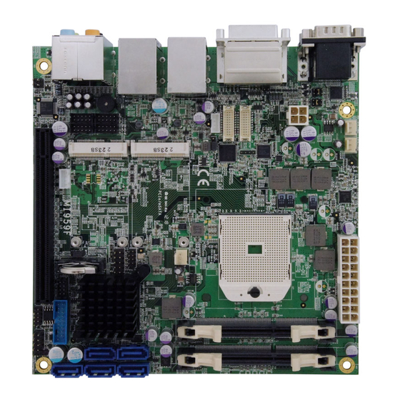
Page 15: Connector Locations On Mi959
INSTALLATIONS Connector Locations on MI959 MI959 User’s Manual... -
Page 16: Cn1: Com1 And Com2 Serial Ports
DATA 5+ DDC DATA SHIELD CLK CLOCK - DATA 1- CLOCK + DATA 1+ Analog RED SHIELD 1/3 Analog Green DATA 3- Analog Blue DATA 3+ Analog HYNC DDC POWER A GROUND2 A GROUND 1 A GROUND3 MI959 User’s Manual... -
Page 17: Cn4: Gigabit + Dual Usb Connector
Signal Name 3.3V 3.3V -12V 3.3V Ground Ground PS-ON Ground Ground Ground Ground Ground Power good 5VSB +12V J2: ATX 12V Power Connector This connector supplies the CPU operating voltage. Pin # Signal Name Ground Ground +12V +12V MI959 User’s Manual... -
Page 18: Cn7, Cn8, Cn9, Cn11, Cn12: Sata3 Connectors
Pin # Signal Name TX0- TX0+ Ground Ground TX1- TX1+ 5V/3.3V Ground TX3- TX3+ TX2- TX2+ Ground Ground TXC- TXC+ 5V/3.3V ENABKL +12V +12V JP8: LCD Backlight Connector Pin # Signal Name +12V Backlight Enable Brightness Control Ground MI959 User’s Manual... -
Page 19: J9: Digital I/O Connector (4 In, 4 Out)
Signal Name Pin # Pin # Signal Name SIN# DCD# SOUT DSR# RTS# CTS# JP11: USB Connectors Signal Name Pin # Pin # Signal Name JP12: SPDIF I/O Pin # Signal Name SPDIF IN Ground SPDIF OUT Ground MI959 User’s Manual... -
Page 20: J18: Audio Pin Header For Chassis Front Panel
CPU_FAN1: CPU Fan Power Connector Pin # Signal Name Ground +12V Rotation detection SYS_FAN1: System Fan Power Connector Pin # Signal Name Ground +12V Rotation detection SYS_FAN2: System Fan Power Connector Pin # Signal Name Ground +12V Rotation detection MI959 User’s Manual... -
Page 21: Bios Setup
The topics covered in this chapter are as follows: BIOS Introduction ................18 BIOS Setup ..................18 Advanced Settings ................20 Chipset Settings ................. 27 Boot Settings ..................31 Security Settings ................33 Save & Exit Settings ................34 MI959 User’s Manual... -
Page 22: Bios Introduction
<PgUp> and <PgDn> keys to change entries, <F1> for help and <Esc> to quit. When you enter the Setup utility, the Main Menu screen will appear on the screen. The Main Menu allows you to select from various setup functions and exit choices. MI959 User’s Manual... - Page 23 F1: General Help F2: Previous Values F3: Optimized Default F4: Save ESC: Exit System Date Set the Date. Use Tab to switch between Data elements. System Time Set the Time. Use Tab to switch between Data elements. MI959 User’s Manual...
-
Page 24: Advanced Settings
Value to be programmed into PCI Latency Timer Register. VGA Palette Snoop Enables or disables VGA Palette Registers Snooping. PERR# Generation Enables or disables PCI device to generate PERR#. SERR# Generation Enables or disables PCI device to generate SERR#. MI959 User’s Manual... - Page 25 Enables or Disables System ability to Hibernate (OS/S4 Sleep State). This option may be not effective with some OS. ACPI Sleep State Select ACPI sleep state the system will enter, when the SUSPEND button is pressed. Lock Legacy Resources Enabled or Disabled Lock of Legacy Resources. MI959 User’s Manual...
- Page 26 PPC Adjustment Provide to adjust _PPC object. NX Mode Enable/disable No-execute page protection function. SVM Mode Enable/disable CPU Virtualization. CPB Mode Enable/disable CPB. C6 Mode Auto/disable CPB. Node 0 Information View memory information related to Node 0. MI959 User’s Manual...
- Page 27 Not Present ↑↓ Select Item SATA Port2 Not Present Enter: Select SATA Port3 Not Present Change Field F1: General Help SATA Port4 Not Present F2: Previous Values SATA Port5 Not Present F3: Optimized Default F4: Save ESC: Exit MI959 User’s Manual...
- Page 28 Schedule Slot 2 None Change Field F1: General Help F2: Previous Values F3: Optimized Default F4: Save ESC: Exit Power-On after Power failure Enable or Disable. Schedule Slot 1 / 2 Setup the hour/minute for system power on. MI959 User’s Manual...
- Page 29 Maximum time the device will take before it properly reports itself to the Host Controller. ‘Auto’ uses default value: for a Root port it is 100ms, for a Hub port the delay is taken from Hub descriptor. MI959 User’s Manual...
- Page 30 F4: Save 1.5V +1.512 V ESC: Exit Temperatures/Voltages These fields are the parameters of the hardware monitoring function feature of the motherboard. The values are read-only values as monitored by the system and show the PC health status. MI959 User’s Manual...
-
Page 31: Chipset Settings
OnChip SATA Type Native iDE → ← Select Screen OnChip iDE mode Legacy mode SATA IDE Combined Mode Enabled ↑↓ Select Item Enter: Select Change Field F1: General Help F2: Previous Values F3: Optimized Default F4: Save ESC: Exit MI959 User’s Manual... - Page 32 OnChip SATA Channel Enabled or Disabled. OnChip SATA Type Native IDE /n RAID /n AHCI /n AHCI /n Legacy IDE /n IDE->AHCI /n HyperFlash OnChip IDE mode Legacy mode or Native mode SATA IDE Combined Mode Enabled or Disabled. MI959 User’s Manual...
- Page 33 Integrated Graphics Auto ↑↓ Select Item Enter: Select Change Field F1: General Help F2: Previous Values F3: Optimized Default F4: Save ESC: Exit Primary Video Device Select Primary Video Device Integrated Graphics Options are Auto Disabled and Force MI959 User’s Manual...
- Page 34 F2: Previous Values F3: Optimized Default F4: Save ESC: Exit LVDS Control NB PCIE Connect Type (Display device) Per Color Mode Number of bit per color mode LVDS Panel Config Select Default is set to LVDS Option 2 1024*768 MI959 User’s Manual...
-
Page 35: Boot Settings
UPON REQUEST – GA20 can be disabled using BIOS services. ALWAYS – do not allow disabling GA20; this option is useful when any RT code is executed above 1MB. Option ROM Messages Set display mode for Option ROM. Options are Force BIOS and Keep Current. MI959 User’s Manual... - Page 36 Controls the execution of UEFI and Legacy Storage OpROM. Launch Video OpROM policy Controls the execution of UEFI and Legacy Video OpROM. Other PCI device ROM priority For PCI devices other than Network, Mass storage or Video defines which OpROM to launch. MI959 User’s Manual...
-
Page 37: Security Settings
Secure Boot flow control. Secure Boot is possible only if System runs in User Mode. Secure Boot Policy Select Secure Boot mode extended options: Internal FV, Option ROM, Removable Media, Fixed Media. Administrator Password Set Setup Administrator Password. MI959 User’s Manual... -
Page 38: Save & Exit Settings
Discard Changes done so far to any of the setup options. Restore Defaults Restore/Load Defaults values for all the setup options. Save as User Defaults Save the changes done so far as User Defaults. Restore User Defaults Restore the User Defaults to all the setup options. MI959 User’s Manual... -
Page 39: Drivers Installation
VGA Drivers Installation ..............36 Audio Drivers Installation ..............40 LAN Drivers Installation ..............41 IMPORTANT NOTE: After installing your Windows operating system, you must install first the Intel Chipset Software Installation Utility before proceeding with the drivers installation. MI959 User’s Manual... -
Page 40: Vga Drivers Installation
DRIVERS INSTALLATION VGA Drivers Installation 1. Insert the drivers DVD that comes with the board. Click AMD, then AMD A70M Chipset Drivers. 2. Click AMD A70M Series Graphics Drivers. MI959 User’s Manual... - Page 41 DRIVERS INSTALLATION 3. When the welcome screen appears, click Next. 4. Select the language you would like to be displayed and click Next. MI959 User’s Manual...
- Page 42 DRIVERS INSTALLATION 5. Click Next to continue the installation process. 6. Select Express and the installation location and click Next. MI959 User’s Manual...
- Page 43 DRIVERS INSTALLATION 7. Click Accept to accept the End User License Agreement. 8. To reboot the system, click Yes. MI959 User’s Manual...
-
Page 44: Audio Drivers Installation
1. Insert the drivers DVD that comes with the board. Click AMD, then Realtek High Definition Audio Driver. 2. When the Welcome screen to the InstallShield Wizard appears, click Next. 3. InstallShield Wizard is now complete, click Finish to restart the system and for changes to take effect. MI959 User’s Manual... -
Page 45: Lan Drivers Installation
DRIVERS INSTALLATION LAN Drivers Installation 1. Insert the drivers DVD that comes with the board. Click LAN Card. 2. Click Realtek LAN Controller Drivers. MI959 User’s Manual... - Page 46 DRIVERS INSTALLATION 3. Click Realtek RTL8111E LANDrivers. 4. When the Welcome screen appears, click Next. 5. Now click Install to begin the installation. 6. InstallShield Wizard is complete. Click Finish. MI959 User’s Manual...
-
Page 47: Appendix
Motherboard resources 00F0h-00FFh Numeric data processor 0170h-0177h ATA Channel 1 01F0h-01F7h ATA Channel 0 0238H-023Fh Communications Port (COM5) 02E8H-02EFh Communications Port (COM4) 02F8H-02FFh Communications Port (COM2) 0338H-033Fh Communications Port (COM6) 03E8H-03EFh Communications Port (COM3) 03F8H-03FFh Communications Port (COM1) MI959 User’s Manual... -
Page 48: Interrupt Request Lines (Irq)
IRQ 18 Standard Open HCD USB Host Controller IRQ 18 Standard Open HCD USB Host Controller IRQ 18 Standard Open HCD USB Host Controller IRQ 19 PCI standard PCI-to-PCI bridge IRQ 19 AMD SATA Controller (IDE Mode) MI959 User’s Manual... -
Page 49: Watchdog Timer Configuration
**endptr; char SIO; printf("6106 watch dog program\n"); bTime = strtol (argv[1], endptr, 10); printf("System will reset after %d seconds\n", bTime); if (bTime) else if (bTime > 0 && bTime < 256) A=2; unsigned char result; Set_6106_LD(0x08); gotoxy(1,12); MI959 User’s Manual... - Page 50 APPENDIX return 0; //--------------------------------------------------------------------------- void EnableWDT(int interval) unsigned char bBuf; Set_6106_LD(0x08); Set_6106_Reg(0x30, 0x01); Set_6106_Reg(0xF1, interval); //--------------------------------------------------------------------------- void DisableWDT(void) unsigned char bBuf; Set_6106_LD(0x08); Set_6106_Reg(0x30, 0x00); //--------------------------------------------------------------------------- MI959 User’s Manual...
- Page 51 Lock_6106 (void) outportb(6106_INDEX_PORT, 6106_LOCK); //--------------------------------------------------------------------------- void Set_6106_LD( unsigned char LD) Unlock_6106(); outportb(6106_INDEX_PORT, 6106_REG_LD); outportb(6106_DATA_PORT, LD); Lock_6106(); //--------------------------------------------------------------------------- void Set_6106_Reg( unsigned char REG, unsigned char DATA) Unlock_6106(); outportb(6106_INDEX_PORT, REG); outportb(6106_DATA_PORT, DATA); Lock_6106(); //--------------------------------------------------------------------------- unsigned char Get_6106_Reg(unsigned char REG) MI959 User’s Manual...
- Page 52 APPENDIX unsigned char Result; Unlock_6106(); outportb(6106_INDEX_PORT, REG); Result = inportb(6106_DATA_PORT); Lock_6106(); return Result; //------------------------------------------------------------------------------------ MI959 User’s Manual...
Need help?
Do you have a question about the MI959 and is the answer not in the manual?
Questions and answers