Table of Contents
Advertisement
Quick Links
Installation and Operating Instructions
Built-In Gas Cooktops
To avoid the risk of accidents or damage to the Gas Cooktops,
it is essential to read these operating instructions
before it is installed or used for the first time.
And please keep this manual for later reference.
HB6422BRU
P/No.: MFL62060313
www.lg.com
Advertisement
Table of Contents

Related Manuals for LG HB6422BGF


Summary of Contents for LG HB6422BGF
- Page 1 To avoid the risk of accidents or damage to the Gas Cooktops, it is essential to read these operating instructions before it is installed or used for the first time. And please keep this manual for later reference. HB6422BRU www.lg.com P/No.: MFL62060313...
-
Page 2: Table Of Contents
Contents Introduction ................. 3 1. Instructions for safe and proper use ........3 Instructions for the installer ............5 2. Positioning of the hob ............5 3. Electrical connection .............. 7 4. Gas connection ..............8 5. Adaptation to different types of gas ........10 6. -
Page 3: Introduction
Introduction 1. Instructions for safe and proper use This manual is an integral part of the appliance and therefore must be kept in its entirety and in an accessible place for the whole working life of the cooking hob. We advise reading this manual and all the instructions therein before using the cooking hob. - Page 4 Introduction The identification plate, with technical data, serial number and marking is clearly visible under the casing. The plate on the casing must not be removed. Before connecting the device, make sure that it has been regulated for the type of gas that will feed it, checking the label under the casing. Do not put pans without perfectly smooth and flat bottoms on the cooking hob grids.
-
Page 5: Instructions For The Installer
Instructions for the installer 2. POSITIONING OF HOB The following operation requires building and/or carpentry work so must be carried out by a competent tradesman. Installation can be carried out on various materials such as masonry, metal, solid wood or plastic laminated wood as long as they are heat resistant (T 90°C). - Page 6 Instructions for the installer Accurately position the gasket provided all around the outer edge of the hole in the top surface as shown in the figures below, pressing it down so as to make it adhere properly. For measurements, refer to the figure depending on the hob model to be installed, bearing in mind that in both models the front and rear sides must skim the hole.
-
Page 7: Electrical Connection
3. Electrical connection Make sure that the voltage and capacity of the power line conform to the data shown on the plate located under the casing. Do not remove this plate for any reason. The plug on the end of the supply cable and the wall socket must be the same type and conform to the current electrical system regulations. -
Page 8: Gas Connection
Instructions for the installer 4. GAS CONNECTION Connection to the gas mains may be made with a rigid copper pipe or with a flexible pipe and conforming to the provisions defined by standard regulations in force. To facilitate connection, fitting A on the rear of the appliance may be adjusted laterally. - Page 9 4.1 Connection to LPG Use a pressure regulator and make the connection to the tank according to the provisions of standards regulations in force. Make sure that feed pressure conforms to the levels shown in the table in paragraph “5.2 Regulation for LPG”. 4.2 Ventilation of rooms The hob may be installed only in rooms with permanent ventilation, as required by standards regulations in force.
-
Page 10: Adaptation To Different Types Of Gas
Instructions for the installer 5. ADAPTATION TO DIFFERENT TYPES OF GAS Before performing any cleaning or maintenance work, detach the appliance from the electrical socket. The hob has been inspected for G20 (2H) natural gas at a pressure of 20 mbar. For functioning with other types of gas the nozzles must be replaced and the primary air adjusted. - Page 11 5.2 Regulation for LPG Loosen screw A and push support B all the way. Use a double head wrench to remove nozzle C and assemble the suitable one, following the instructions indicated in the reference charts, with respect to the type of gas to use. The screwing torque of the nozzle should never exceed 3 Nm.
- Page 12 Instructions for the installer 5.3 Regulation for natural gas The hob has been inspected for G20 (2H) natural gas at a pressure of 20 mbar. To allow the unit to work with this type of gas, perform the same operations described in paragraph “5.2 Regulation for LPG”, but choose the nozzles and regulate the primary air for natural gas, as shown in the following table and in paragraph "5.4 Regulation of primary air”.
-
Page 13: Final Operations
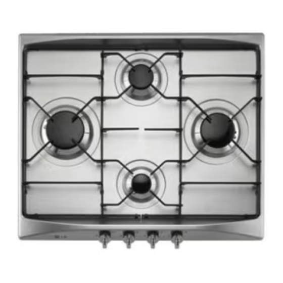
6. Final operations Having carried out the above adjustments, reassemble the appliance following, backwards, the instructions in paragraph “5.1 Removing the hob”. 6.1 Regulation of minimum for natural gas Replace the components on the burner and slide the knobs on the gas tap pins. Light the burner and set it at minimum position. - Page 14 Instructions for the installer 6.3 Arrangement of burners on hob BURNERS 1. Auxiliary 2. Semi-rapid 3. Rapid 4. Rapid 5. Ultra rapid 6.4 Lubrication of gas taps After a while, the gas tap may become hard to turn or lock. If this happens, it has to be cleaned inside and re-greased.
-
Page 15: Instructions For The User
Instructions for the user 7. Using the hob Before turning on the burners, make sure that the burner rings, caps and grids have been fitted correctly. In the Wok burner, notch A must be aligned with pin B. Grid C provided is intended for use with woks (Chinese pans). Adapter D comes only with open grids models and is intended for use with small sized vessels. - Page 16 Instructions for the user 7.2 Practical advice for using the burners For better burner performance and minimum gas consumption, flat bottomed, even recipients must be used, with covers and proportional in size to the burners (see paragraph “7.3 Diameter of containers”). To avoid overcooking or damage to the surface top while cooking, all recipients or griddles must be positioned within the cooking hob perimeter and must be a minimum distance of 3-4 cm from the knobs.
-
Page 17: Cleaning And Maintenance
8. Cleaning and maintenance Never use a steam jet to clean the appliance. Before any intervention, disconnect the power supply of the device. 8.1 Cleaning Clean the cooking top regularly every time you use it, obviously after it has cooled. 8.1.1 Regular daily cleaning of the hob In order to clean and preserve the surface, always use specific products only, which do not contain abrasive substances or... - Page 18 Instructions for the user 8.2 Cleaning of cooking hob components CAUTION: do not wash these components in a dishwasher. In normal use of the hob, the stainless steel burner caps and pan- stands tend to be burnished by the high temperature. Clean these parts using very fine abrasive sponges or similar commercial products.
- Page 20 Printed in Italy...
Need help?
Do you have a question about the HB6422BGF and is the answer not in the manual?
Questions and answers