Advertisement
Quick Links
(Draft 07/20/2022)
MODEL SR446
DC to 400 MHz PROGRAMMABLE GAIN PREAMPLIFIER
1290-D Reamwood Avenue
Sunnyvale, California 94089
Phone: (408) 744-9040 • Fax: (408) 744-9049
email: info@thinkSRS.com • www.thinkSRS.com
Copyright © 2022 by SRS, Inc.
All Rights Reserved.
Advertisement

Related Manuals for SRS Labs SR446


Summary of Contents for SRS Labs SR446
- Page 1 (Draft 07/20/2022) MODEL SR446 DC to 400 MHz PROGRAMMABLE GAIN PREAMPLIFIER 1290-D Reamwood Avenue Sunnyvale, California 94089 Phone: (408) 744-9040 • Fax: (408) 744-9049 email: info@thinkSRS.com • www.thinkSRS.com Copyright © 2022 by SRS, Inc. All Rights Reserved.
-
Page 2: Warranty
Revision 1.0 (05/2022) Certification Stanford Research Systems certifies that this product met its published specifications at the time of shipment. Warranty This Stanford Research Systems product is warranted against defects in materials and workmanship for a period of one (1) year from the date of shipment. Service For warranty service or repair, this product must be returned to a Stanford Research Systems authorized service facility. - Page 3 Page 3 of 15...
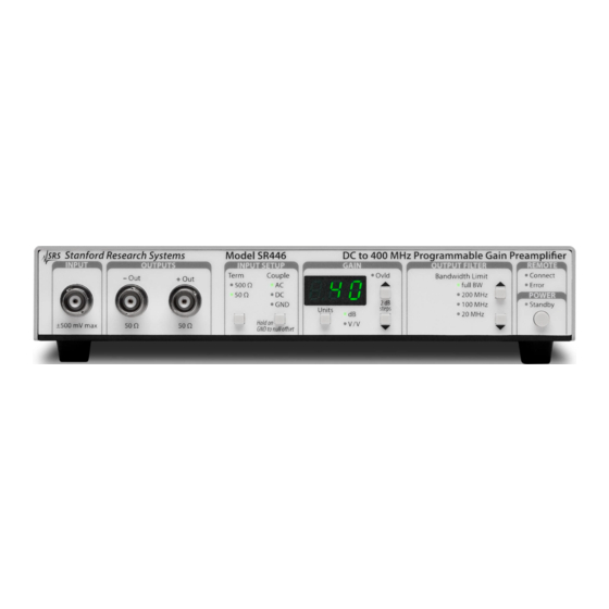
- Page 4 SR446 Front Panel SR446 Rear Panel Page 4 of 15...
-
Page 5: Operation
SR446 Programmable Amplifier Description The SR446 is a single-channel, 400 MHz bandwidth voltage preamplifier with 21 programmable gains from ×1 to ×100 (+0 dB to +40 dB with 2 dB steps). It also includes four programmable low-pass filters, with settings of full bandwidth, 200 MHz, 100 MHz and 20 MHz. There are two output channels which offer complimentary outputs (inverting and non-inverting) that can be used separately, or together as a differential output. - Page 6 SR446 Specifications Specification Units Inputs (driven by 50-Ω source) Input signal level -500 +500 AC mode cutoff (-3 dB) 50 Ω 500 Ω Impedance (at DC) 50 Ω Ω 500 Ω Ω Input clamp levels -1.5 +1.5 nV/ √ ��������...
- Page 7 Frequency Response AC mode, Input impedance = 50 Ω, Full bandwidth, input signal = 130mVpk-pk., sinusoidal wave Typical AC Gain vs Frequency 0.01 0.10 1.00 10.00 100.00 1,000.00 Frequency, MHz Page 7 of 15...
- Page 8 Commands are listed in the remote interface section below. For accurate calibration, power on the SR446 and wait for least 20 minutes to ensure it is warm AC gain calibration compare output signal with respect to input signal at a given frequency. One recommendation is to use lock-in amplifier like SR865A.
- Page 9 Recommended test equipment: SR865A (Stanford Research Systems) 50 Ω load (Pomona P/N 4391-50 or equivalent) Coaxial cables of RG-58 type (Pomona P/N 5697-36 or equivalent) Trim pot adjustment tool (Aven P/N1322 or equivalent) SR865A settings: Refer to SR865A operations manual, configure following parameters: Reset the instrument o Press “Save Recall”...
- Page 10 SR446 settings: Input impedance: 50 Ω Input couple: DC Gain: 1 V/V or 0 dB Bandwidth: Full Trim pot locations R412 is on the left. R512 is on the right. Page 10 of 15...
- Page 11 Test procedures: 1. Remove the top cover of the SR446. Power up and configure the unit as stated above. Wait at least 20 minutes to warm up the device. 2. Power up and configure the SR865A as stated above. Wait at least 20 minutes to warm up the device.
- Page 12 Power Supplies The unit operates from a universal input power supply. The power supply can operate from AC mains with 85 ~ 264 VAC and 47 ~ 63 Hz. Typical power consumption is 5 W. Page 12 of 15...
- Page 13 Remote command list: Only the host can initiate a command. The SR446 can only send response to a query and it does not echo back the command sent. The system will clear some error flags after respond to the query. All messages are ASCII strings.
- Page 14 <n>: decimal digit Commands Responses Remarks *IDN? <System message> System message = “Stanford_Research_Systems,SR446, <Serial Number>, <Revision number>” *RST None Reset configuration to default settings. Copy factory settings to last settings and current settings. EEPROM update might be delayed up to 30 seconds.
- Page 15 The system flag is an 8-digit hexadecimal number. The bits are arranged from MSB to LSB with LSB being bit 0. Example: 000000020 means bit 5 is set. Bit definitions are listed below: BIT0: Unknow command BIT1: Invalid parameter BIT2: Console communication error BIT3: Front panel communication error BIT4: Analog board communication error BIT5: EEPROM error...
Need help?
Do you have a question about the SR446 and is the answer not in the manual?
Questions and answers