Table of Contents
Advertisement
Quick Links
Advertisement
Table of Contents

Subscribe to Our Youtube Channel
Related Manuals for Cobalt Digital Inc 9450GT Series


Summary of Contents for Cobalt Digital Inc 9450GT Series
- Page 1 9450GT Fiber Ethernet Switch Transceivers Product Manual 9450GT-OM Version: 1.1...
- Page 2 Notice notice. Trademarks • Cobalt® is a registered trademark of Cobalt Digital Inc. • openGear® is a registered trademark of Ross Video Limited. • DashBoard Control System™ is a trademark of Ross Video Limited. • All other product names and any registered and unregistered trademarks mentioned in this manual are used for identification purposes only and remain the exclusive property of their respective owners.
- Page 3 Important Regulatory and Safety Notices to Service Personnel Before using this product and nay associated equipment, refer to the “Important Safety Instructions” listed below to avoid personnel injury and to prevent product damage. Product may require specific equipment, and/or installation procedures to be carried out to satisfy certain regulatory compliance requirements.
- Page 4 Warning — This product includes an “Ethernet Port” which allows this product to be connected to a local area network (LAN). Only connect to networks that remain inside the building. Do not connect to networks that go outside the building. EMC Notices United States of America FCC Part 15...
- Page 5 Important Laser Safety Measures and Notices Before using this product and any associated equipment, refer to the sections below so as to avoid personnel injury and to prevent product damage. For further safety information when using fiber products, consult the following publications: •...
- Page 6 Environmental Information The equipment that you purchased required the extraction and use of natural resources for its production. It may contain hazardous substances that could impact health and the environment. To avoid the potential release of those substances into the environment and to diminish the need for the extraction of natural resources, you are encouraged to use the appropriate take-back systems.
-
Page 8: Table Of Contents
Contents Introduction Overview................................... 1-2 Features..................................... 1-3 User Interfaces .................................. 1-4 Documentation Terms and Conventions ..........................1-5 Installation Before You Begin................................2-2 Physical Installation ................................2-3 Installing a Rear Module ..............................2-3 Installing a Card ................................2-4 Ethernet Communications..............................2-5 Ethernet Cabling Overview ............................... 2-5 Internal GigE Link ................................ - Page 9 Warranty and Repair Policy............................... 5-3 Contact Cobalt Digital Inc..............................5-4 Visit us at the Cobalt Digital Inc. website......................... 5-4 ii • • • • Contents Fiber Ethernet Switch Transceivers Product Manual (V1.1)
-
Page 11: Introduction
Introduction In This Chapter This chapter contains the following sections: • Overview • Features • User Interfaces • Documentation Terms and Conventions Introduction • • • • 1-1 Fiber Ethernet Switch Transceivers Product Manual... -
Page 12: Overview
Overview The Fiber Ethernet Switch Transceivers are configured in various modes depending on the number of small form-factor pluggable fiber transceivers (SFPs) installed and the rear module used. There are up to six user ports (a combination of fiber optic and RJ45 connectors) plus one GigE (SERDES) port connected to the OG3-FR series frame midplane that communicates with the switch on the MFC-8322-N Network Controller cards. -
Page 13: Features
Features The following features are common for the Fiber Ethernet Switch Transceivers: • Compliant with IEEE 802.3 (10/100/1000BASE-T, 1000BASE-X) • Supports 10/100/1000 Base T Ethernet on RJ45 connectors • Auto negotiation for 10/100/1000 speeds, half/full duplex modes, MDI/MDIX auto-crossover • Supports two trunk groups between two devices with each trunk group having up to four ports •... -
Page 14: User Interfaces
User Interfaces The following interfaces are available for your Fiber Ethernet Switch Transceiver. DashBoard Control System The DashBoard Control System enables you to monitor and control openGear frames and cards from a computer. DashBoard communicates with the Fiber Ethernet Switch Transceiver and other cards in the openGear frame through the Network Controller Card. -
Page 15: Documentation Terms And Conventions
Documentation Terms and Conventions The following terms and conventions are used throughout this manual. Terms The following terms are used: • “Board”, and “Card” refer to openGear terminal devices within openGear frames, including all components and switches. • “CWDM” refers to models that include Coarse Wavelength Division Multiplexing lasers. •... - Page 16 1-6 • • • • Introduction Fiber Ethernet Switch Transceivers Product Manual (Product Manual)
-
Page 17: Installation
Installation In This Chapter This chapter provides instructions for installing the rear module(s) for the Fiber Ethernet Switch Transceivers, installing the cards into the frame, cabling details, and updating the software. The following topics are discussed: • Before You Begin •... -
Page 18: Before You Begin
Before You Begin Before proceeding with the instructions in this chapter, ensure that your openGear frame is properly installed according to the instructions in its manual. Important — Contact your IT Department before connecting to your facility network to ensure that there are no conflicts or the possibility of creating a network loop. Static Discharge Throughout this chapter, please heed the following cautionary note: ESD Susceptibility... -
Page 19: Physical Installation
Physical Installation This section outlines how to install a rear module and a card in an openGear frame. However, the specific rear module you need to install depends on your application. The internal GiGE interface is available only when the card is installed in an OG3-FR series frame. Installing a Rear Module If the rear module is already installed, proceed to the section “Installing a Card”. -
Page 20: Installing A Card
Installing a Card Refer to the section “Important Laser Safety Measures and Notices” at the beginning of this manual for safety information when handling fiber optic components. To install the card in an openGear frame 1. Locate the rear module you installed in the procedure “Installing a Rear Module”. 2. -
Page 21: Ethernet Communications
Ethernet Communications The RJ45 ports on the rear modules support 10/100/1000 Base T Ethernet communications. The number of ports depends on the card model you are using. In addition to the Ethernet ports on the rear module, you must also provide an ethernet connection to the openGear frame as outlined in its manual. -
Page 22: Software Upgrades
Software Upgrades This section provides instructions for upgrading the software for your card using the DashBoard Control System. To upgrade the software on your card 1. Contact Technical Support for the latest software version file. 2. In DashBoard, display the Device View of the card by double-clicking its status indicator in the Basic Tree View. -
Page 23: 9450Gt Setup
9450GT Setup In This Chapter This chapter provides the cabling designations and the technical specifications for the 9450GT Single Link Ethernet Fiber Transceivers. Note that specifications are subject to change without notice. The following topics are discussed: • 9450GT Overview •... -
Page 24: 9450Gt Overview
9450GT Overview The 9450GT series provide a two fiber, and four copper (RJ45) Ethernet ports. This gives you five links (one fiber and four RJ-45) plus the Internal Link interface. Each card uses a standard SFP with an FP 1310nm laser and PIN receiver. High power and CWDM transmitters are available, as is a high sensitivity receiver. -
Page 25: 9450Gt Functional Block Diagram
This section provides a functional block diagram that outlines the workflow of the 9450GT series regardless of the model type. (Model 9450GT-NF omits the fiber I/O interfaces.) Figure 3.1 9450GT Series — Simplified Block Diagram 9450GT Setup • • • • 3-3... -
Page 26: Cabling For The 9450Gt
Cabling for the 9450GT This section provides information for connecting cables to the installed Rear Module on the openGear frames. The optical connector used to mate the card to the rear module is designed for blind mate optical connections. Caution —... -
Page 27: 9450Gt Technical Specifications
1270-16 1 0nm 9450GT-80 1550nm 1270-16 1 0nm 9450GT Technical Specifications This section provides the technical specifications for the 9450GT series. 9450GT-20/40/80 Series This section provides the technical specifications for the 9450GT-20, 9450GT-40, and 9450GT-80. Table 3.6 9450GT Technical Specifications... -
Page 28: 9450Gt Cwdm Series
9450GT CWDM Series This section provides the technical specifications for the 9450GT CWDM series. Table 3.7 9450GT CWDM Series Technical Specifications Category Parameter Specification Number of Inputs Number of Outputs 9450GT-27: 1270nm 9450GT-29: 1290nm 9450GT-31: 1310nm 9450GT-33: 1330nm 9450GT-35: 1350nm 9450GT-37: 1370nm 9450GT-43: 1430nm 9450GT-45: 1450nm... -
Page 29: Configuration
Configuration In This Chapter This chapter provides a general overview of the user controls and configuration options available for your F iber Ethernet Switch Transceiver. The following topics are discussed: • Card Overview • Control and Monitoring Features • Configuring a VLAN •... -
Page 30: Card Overview
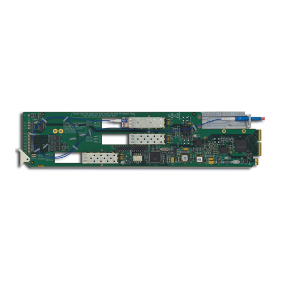
Card Overview This section provides a general overview of the Fiber Ethernet Switch Transceiver card-edge components. For information on the available LEDs, refer to the section “Control and Monitoring Features”. The card-edge components are the same regardless of the card model, but the number of optic connectors may differ. Figure 4.1 Typical Layout 1. -
Page 31: Control And Monitoring Features
Control and Monitoring Features This section provides information on the power status LED located on the card-edge and the LEDs on all rear modules for the Fiber Ethernet Switch Transceivers. Note — The number of SFP and PORT LEDs that are implemented on the card-edge is dependent on your card model. -
Page 32: Card-Edge Leds Overview
Card-edge LEDs Overview Basic LED displays and descriptions are provided in Table 4.2. Table 4.2 Card-edge LEDs Color Display and Description When lit green, this LED indicates that the card is functioning normal and Green that no anomalies have been detected. When flashing green, this LED indicates that the bootloader is currently Flashing Green running. - Page 33 Rear Module LEDs Overview Basic LED descriptions are provided in Table 4.3. Table 4.3 LEDs on the Rear Module Color Display and Description When lit green, this LED indicates a valid link is established on the specified Green RJ45 port. ETHERNET When flashing green, this LED indicates communication activity is occurring Flashing Green...
-
Page 34: Enabling Trunking
Enabling Trunking Trunking, also known as link aggregation, is the use of two or more links between nodes (switches and/or servers) in parallel to increase the bandwidth. A side benefit is that a failure of a link will cause the traffic to be redistributed among the remaining links, though at reduced overall capacity. -
Page 35: Enabling Alarms
Enabling Alarms You can configure the Fiber Ethernet Switch Transceivers to report when one or more of the following error conditions occur: • A link fails on the card switch • An incompatible rear module is installed with the card •... -
Page 36: Incompatible Rear Module Monitoring
Select the Enable Fiber Abnormal Temperature check box for the fiber optic connection you wish to monitor. Incompatible Rear Module Monitoring You can choose to enable the card to report when an unsupported rear module is installed with your card. This alarm is reported in the HW Status field in the Hardware tab. - Page 37 DashBoard Menus In This Chapter This chapter briefly summarizes the menus, items, and parameters available from the DashBoard Control System for the Fiber Ethernet Switch Transceiver. Note that default values are indicated with an asterisk (*). The following topics are discussed: •...
-
Page 38: Status Tabs
Status Tabs This section summarizes the read-only information displayed in the Status tabs. The fields in the Status tabs can vary in severity from green (valid), yellow (caution), to red (alarm). DashBoard reports the most severe alarm for a single field. Alarm colors are noted within the tables as text set in brackets next to the menu parameter name. - Page 39 Table 4.1 Signal Tab Items Tab Title Item Parameters Description # Mbps Indicates the duplex and speed of the specified port # Gbps Fiber # Rate The link has failed No Link The link is invalid # Mbps Indicates the duplex and speed of the Ports GigE connection to the OG3-FR # Gbps...
-
Page 40: Hardware Tab
Table 4.3 Product Tab Items Tab Title Item Parameters Description Product Displays the card name Supplier Cobalt Digital Inc. Board Rev Indicates the board revision Board S/N ###### Indicates the card serial number Product Indicates the Rear Module installed Rear Module Software Rev ##.##... - Page 41 Fiber Ethernet Switch Transceivers Product Manual (Product Manual) DashBoard Menus • • • • 4-13...
-
Page 42: Port Stats Tab
Port Stats Tab Table 4.4 summarizes the read-only information displayed in the Port Stats tab. Note — The number of RJ45 and Fiber Link Status fields in the Port Stats tab is dependent on your card model. Table 4.4 Port Stats Tab Items Menu Title Item Parameters... -
Page 43: Setup Tab
Setup Tab Table 4.5 summarizes the Setup options available in DashBoard. Note that the number of configurable Port fields in the Setup tab is dependent on your card model. Important — Contact your IT Department before connecting to your facility network to ensure that there are no conflicts or the possibility of creating a network loop. -
Page 44: Alarm Enable Tab
Alarm Enable Tab Table 4.6 summarizes the Alarm setup options available in DashBoard. Note — The number of sub-tabs, RJ45 Link check boxes, and Fiber Link check boxes in the Alarm Enable tab is dependent on your card model. Table 4.6 Alarm Enable Menu Items Menu Title Item Parameters... - Page 45 Table 4.6 Alarm Enable Menu Items Menu Title Item Parameters Description Enables the corresponding Optical Tx Power field in the Signal tab to report Selected* when the optical receiver power of the TX Power Low Optical Module is less than X#dBm Cleared Disables this alarm for the specified port Enables the corresponding Optical Rx...
-
Page 47: Service Information
Service Information In This Chapter This chapter contains the following sections: • Troubleshooting Checklist • Warranty and Repair Policy Fiber Ethernet Switch Transceivers Product Manual (Product Manual) Service Information • • • • 5-1... -
Page 48: Troubleshooting Checklist
Troubleshooting Checklist Routine maintenance to this openGear product is not required. In the event of problems with your Fiber Ethernet Switch Transceiver, the following basic troubleshooting checklist may help identify the source of the problem. If the frame still does not appear to be working properly after checking all possible causes, please contact your openGear products distributor, or the Technical Support department at the numbers listed under the “Contact Us”... - Page 49 (1) year. Cobalt Digital Inc.'s (“Cobalt”) sole obligation under this warranty shall be limited to, at its option, (i) the repair or (ii) replacement of the product, and the determination of whether a defect is covered under this limited warranty shall be made at the sole discretion of Cobalt.
- Page 50 Technical Support PHONE 217.344.1245 General Information Info@cobaltdigital.com E-MAIL Sales Information Sales@cobaltdigital.com 2506 Galen Drive POSTAL Cobalt Digital Inc. Champaign, IL 6 1 821 USA SERVICE Visit us at the Cobalt Digital Inc. website. http://www.cobaltdigital.com/ • Online catalog • Related products and full product lines • Trade show information •...
Need help?
Do you have a question about the 9450GT Series and is the answer not in the manual?
Questions and answers