Advertisement
Quick Links
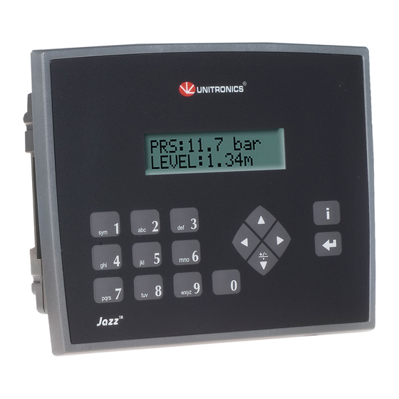
Jazz™PLC+HMI
JZ20-T10/JZ20-J-T10
JZ20-T18/JZ20-J-T18
JZ20-J-T20HS
Before using this product, the user must read and understand this document.
For additional information regarding this product, refer to the user guide and technical specifications.
All examples and diagrams are intended to aid understanding, and do not guarantee operation.
Unitronics accepts no responsibility for actual use of this product based on these examples.
Please dispose of this product according to local and national standards and regulations.
Only qualified service personnel should open this device or carry out repairs.
Failure to comply with appropriate safety guidelines can cause severe injury or property
damage.
Do not attempt to use this device with parameters that exceed permissible levels.
To avoid damaging the system, do not connect/disconnect the device when power is on.
Environmental Considerations
Do not install in areas with: excessive or conductive dust, corrosive or flammable gas,
moisture or rain, excessive heat, regular impact shocks or excessive vibration.
Ventilation: 10mm space required between the PLC+HMIs' top/bottom edges & enclosure
walls.
Do not place in water or let water leak onto the unit.
Do not allow debris to fall inside the unit during installation.
Mounting
Dimensions
* Note that for JZ20-J modules those dimensions are 7.5 mm (0.295").
Unitronics
Micro-PLC+HMI Installation Guide
6 Digital Inputs including 2 HSC, 4 Transistor Outputs
6 Digital Inputs including 2 HSC, 2 Analog/Digital Inputs,
2 Analog Inputs, 8 Transistor Outputs
6 Digital Inputs including 3 HSC/Shaft-encoder,
2 Analog/Digital Inputs, 2 Analog Inputs,
10 Transistor Outputs
1
Advertisement

Related Manuals for Unitronics JZ20-J-T20HS


Summary of Contents for Unitronics JZ20-J-T20HS
- Page 1 All examples and diagrams are intended to aid understanding, and do not guarantee operation. Unitronics accepts no responsibility for actual use of this product based on these examples. Please dispose of this product according to local and national standards and regulations.
- Page 2 01/16 JZ20-T1X/JZ20-J-T1X/JZ20-J-T20HS Add-on modules- Integral USB Port Available by separate order for This may be used for communication and cloning. programming purposes. Note: the USB port and an Add-on module cannot be physically connected at the same time. Add-on: during installation...
-
Page 3: Wiring Procedure
If I0, I1, I4 are set as high-speed counters (without reset), I2, I3, I5 can function as normal digital inputs. The following information concerns JZ20-T18/JZ20-J-T18 and JZ20-J-T20HS in addition to I0- I5, these comprise the following: I6 and I7 may be wired as either digital or analog inputs. These may be wired as either: ... - Page 4 01/16 JZ20-T1X/JZ20-J-T1X/JZ20-J-T20HS Digital Inputs, Controller’s Power Supply JZ20-T10/JZ20-J-T10 Input wiring (I0-I5), npn (sink) Input wiring (I0-I5), pnp (source) JZ20-T18/JZ20-J-T18 Note: The inputs are arranged in two groups. You can wire one group as npn and the other as pnp, or wire both groups as npn, or as pnp. In either case, the n/p pins must be connected.
- Page 5 JZ20-T1X/JZ20-J-T1X/JZ20-J-T20HS 01/16 Input wiring, (I0-I5), pnp (source), (I6-I7), npn (sink) HSC input wiring, npn (sink) HSC input wiring, pnp (source) Shaft-encoder wiring, npn (sink) Shaft-encoder wiring, pnp (source) Unitronics...
-
Page 6: Analog Inputs
JZ20-T18/JZ20-J-T18/JZ20-J-T20HS,(AN2-AN3) The information in this document reflects products at the date of printing. Unitronics reserves the right, subject to all applicable laws, at any time, at its sole discretion, and without notice, to discontinue or change the features, designs, materials and other specifications of its products, and to either permanently or temporarily withdraw any of the forgoing from the market.