Table of Contents
Advertisement
CONTENTS
1 GENERAL INFORMATION ...................................................................... 2
2 PRODUCT INFORMATION ...................................................................... 7
V
3 OPERATING INSTRUCTIONS ................................................................10
: ...........................................................................................10
V
4 DIAGNOSTIC TROUBLE CODE (DTC) DEFINITIONS .............................16
(OBD) II ............................................................... 2
..................................................................... 3
................................................................................. 5
.................................................................................... 7
........................................................................... 7
................................................................................... 8
................................................................................... 8
..........................................................................................12
....................................................................................14
...........................................................................................15
.......................................................... 1
) .......................................................... 2
(DLC) ............................................ 3
............................................................ 4
...............................................................13
i
Advertisement
Table of Contents

Related Manuals for Performance Tool MaxiScan MS300


Summary of Contents for Performance Tool MaxiScan MS300
-
Page 1: Table Of Contents
CONTENTS ............1 AFETY RECAUTIONS AND ARNINGS 1 GENERAL INFORMATION ..............2 (OBD) II ............... 2 OARD IAGNOSTICS (DTC ) ............2 IAGNOSTIC ROUBLE ODES (DLC) ..........3 OCATION OF THE ONNECTOR OBD II R ..............3 EADINESS ONITORS OBD II M ............ -
Page 2: Safety Precautions And Warnings
Safety Precautions and Warnings To prevent personal injury or damage to vehicles and/or the Scan Tool, read this instruction manual first and observe the following safety precautions at a minimum whenever working on a vehicle: Always perform automotive testing in a safe environment. ... -
Page 3: General Information
General Information On-Board-Diagnostics (OBD) II The first generation of On-Board Diagnostic (called OBD I), was developed by the California Air Resources Board (ARB) and implemented in 1988 to monitor some of the emission control components on vehicles. As technology evolved and the desire to improve the OBD I system increased, a new generation of On-Board Diagnostics system was developed. -
Page 4: Location Of The Data Link Connector (Dlc)
Location of the Data Link Connector (DLC) The DLC (Data Link Connector or Diagnostic Link Connector) is the standardized 16-cavity connector where diagnostic scan tools interface with the vehicle’s on-board computer. The DLC is usually located 12 inches from the center of the instrument panel (dash), under or around the driver’s side for most vehicles. -
Page 5: Obd Ii Monitor Readiness Status
any vehicle depends on the motor vehicle manufacturer’s emissions control strategy. Continuous Monitors – some of the vehicle components or systems are continuously tested by the vehicle’s OBDII system, while others are tested only under specific vehicle operating conditions. The continuously monitored components listed below are always ready: Misfire Fuel System... -
Page 6: Obd Ii Terminology
will remain in this state. A number of factors, including erasing of diagnostic trouble codes (DTCs) with a scan tool or a disconnected battery, can result in Readiness Monitors being set to “not ready”. Since the three continuous monitors are constantly evaluating, they will be reported as “Ready” all of the time. - Page 7 OBDII Drive Cycle – a specific mode of vehicle operation that provides conditions required to set all the readiness monitors applicable to the vehicle to the “Ready” condition. The purpose of completing an OBD II drive cycle is to force the vehicle to run its onboard diagnostics. Some form of a drive cycle needs to be performed after DTCs have been erased from the PCM’s memory or after the battery has been disconnected.
-
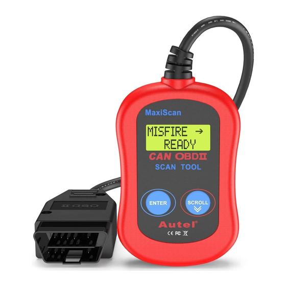
Page 8: Product Information
Product Information Tool Description LCD DISPLAY – indicates test results. It is a backlit 2-line display with 8 characters on each line. ENTER BUTTON – confirms a selection (or action) from a menu list, or returns to the main menu. SCROLL BUTTON –... -
Page 9: Product Features
Weight: 250g (8.9 oz) Product Features Works with all 1996 and newer cars & light trucks that are OBD II compliant (including the CAN, VPW, PWM, ISO and KWP 2000 protocols) Reads and clears generic and manufacturer specific Diagnostic ... - Page 10 For your vehicle to be OBD II compliant it must have a 16-pin DLC (Data Link Connector) under the dash and the Vehicle Emission Control Information Label must state that the vehicle is OBD II compliant.
-
Page 11: Operating Instructions
Operating Instructions Read Codes: CAUTION: Don’t connect or disconnect any test equipment with ignition on or engine running. Turn the ignition off. Locate the 16-pin Data Link Connector (DLC) and plug into the Scan Tool cable connector to the DLC. “C.A.N.OBD2”. - Page 12 If a “LINK ERROR!” message shows up, turn the ignition off for about 10 seconds, check if the Scan Tool’s OBDII connector is securely connected to the vehicle’s DLC, and then turn the ignition back to on. Repeat the procedure from step 5. If the “LINK ERROR” message does not go away, then there may be problems for the Scan Tool to communicate with the vehicle.
-
Page 13: Erase Codes
If the code retrieved is a pending code, a “PD” will show on the LCD display in the end. To view previous codes, press the SCROLL button to scroll through to the end, and then start from the first of the list. Look up part 5 for Diagnostic Trouble Code Definitions. -
Page 14: Retrieve I/M Readiness Status
If you do not want to proceed with erasing the codes, press the SCROLL button to exit. If you do wish to proceed to erase the codes, then press the ENTER button. If the codes are cleared successfully, an “ERASE DONE!” message will show on the display. -
Page 15: View Vin Number
Not RDY(NOT READY) – indicates that a particular monitor being checked has not completed its diagnostic testing N/A – the monitor is not supported on that vehicle → – a flashing Right Arrow indicates additional information is available ... -
Page 16: Rescan Data
If the Scan Tool is not connected yet, then refer to “Read Codes” from 1 to 6. Use the SCROLL button to view additional digits of the 17-digit string. → – a flashing Right Arrow indicates additional digits of VIN string are available on the next screen. -
Page 17: Diagnostic Trouble Code (Dtc) Definitions
Diagnostic Trouble Code (DTC) Definitions The following Diagnostic Trouble Code Definitions lists provide only Generic Diagnostic Trouble Codes. For Manufacturer-Specific Diagnostic Trouble Code Definitions, consult the vehicle’s service manual or the enclosed CD software. CAUTION: Parts or components should not be replaced based on only a DTC without first consulting the vehicle service manual for more information on possible causes of the fault as well as required testing procedures. - Page 18 P0024 Camshaft Position Actuator B - Bank 2 Timing Over-Advanced P0025 Camshaft Position Actuator B - Bank 2 Timing Over-Retarded P0026 Intake Valve-Bank 1 Control Solenoid CKT Range/Performance P0027 Exhaust Valve-Bank 1 Control Solenoid CKT Range/Performance P0028 Intake Valve-Bank 2 Control Solenoid CKT Range/Performance P0029 Exhaust Valve-Bank 2 Control Solenoid CKT Range/Performance P0030...
- Page 19 P0061 HO2S Bank 2 Sensor 3 Heater Resistance P0062 HO2S Bank 2 Sensor 3 Heater Circuit P0063 HO2S Bank 2 Sensor 3 Heater Circuit Low P0064 HO2S Bank 2 Sensor 3 Heater Circuit High P0065 Air Assisted Injector. Control Range/Performance P0066 Air Assisted Injector.
- Page 20 P0098 IAT Sensor 2 Circuit High P0099 IAT Sensor 2 CKT Intermittent P0100 MAF or VAF A Circuit Malfunction P0101 MAF or VAF A Circuit Range/Performance P0102 MAF or VAF A Circuit Low Input P0103 MAF or VAF A Circuit High Input P0104 MAF or VAF A Circuit Intermittent P0105...
- Page 21 P0135 O2 Sensor Heater Circuit Malfunction (Bank 1 Sensor 1) P0136 O2 Sensor Circuit Malfunction (Bank 1 Sensor 2) P0137 O2 Sensor Circuit Low Volts (Bank 1 Sensor 2) P0138 O2 Sensor Circuit High Volts (Bank 1 Sensor 2) P0139 O2 Sensor CKT Slow Response (Bank 1 Sensor 2) P0140 O2 Sensor CKT No Activity (Bank 1 Sensor 2)
- Page 22 P0172 System Too Rich (Bank 1) P0173 Fuel Trim Malfunction (Bank 2) P0174 System Too Lean (Bank 2) P0175 System Too Rich (Bank 2) P0176 Fuel Compensation Sensor Circuit Malfunction P0177 Fuel Compensation Sensor CKT Range/Performance P0178 Fuel Compensation Sensor Circuit Low Input P0179 Fuel Compensation Sensor Circuit High Input P0180...
- Page 23 P0209 Injector Circuit Open Cylinder 9 P0210 Injector Circuit Open Cylinder 10 P0211 Injector Circuit Open Cylinder 11 P0212 Injector Circuit Open Cylinder 12 P0213 Cold Start Injector 1 Malfunction P0214 Cold Start Injector 2 Malfunction P0215 Engine Shutoff Solenoid Malfunction P0216 Injection Timing Control Circuit Malfunction P0217...
- Page 24 P0246 Turbo/Sup Wastegate Solenoid A High P0247 Turbo/Sup Wastegate Solenoid B Malfunction P0248 Turbo /Sup Wastegate Solenoid B Range/Performance P0249 Turbo/Sup Wastegate Solenoid B Low P0250 Turbo/Sup Wastegate Solenoid B High P0251 Injection Pump Metering Control A P0252 Injection Pump Metering Control A Range/Performance P0253 Injection Pump Metering Control A Low P0254...
- Page 25 P0282 Cylinder 8 Injector Control Circuit Low P0283 Cylinder 8 Injector Control Circuit High P0284 Cylinder 8 Contribution Balance Fault P0285 Cylinder 9 Injector Control Circuit Low P0286 Cylinder 9 Injector Control Circuit High P0287 Cylinder 9 Contribution Balance Fault P0288 Cylinder 10 Injector Control Circuit Low P0289...
- Page 26 P0319 Rough Road Sensor B P0320 Ignition/Dist Engine Speed Input Circuit Malfunction P0321 Ignition/Dist Engine Speed Input CKT Range/Performance P0322 Ignition/Dist Engine Speed Input Circuit No Signal P0323 Ignition/Dist Engine Speed Input CKT Intermittent P0324 Knock Control System Malfunction P0325 Knock Sensor 1 Circuit Malfunction Bank 1 or 1 Sensor P0326 Knock Sensor 1 CKT Range/Performance Bank 1 or 1 Sensor...
- Page 27 P0356 Ignition Coil F Primary/Secondary Circuit Malfunction P0357 Ignition Coil G Primary/Secondary Circuit Malfunction P0358 Ignition Coil H Primary/Secondary Circuit Malfunction P0359 Ignition Coil I Primary/Secondary Circuit Malfunction P0360 Ignition Coil J Primary/Secondary Circuit Malfunction P0361 Ignition Coil K Primary/Secondary Circuit Malfunction P0362 Ignition Coil L Primary/Secondary Circuit Malfunction P0363...
- Page 28 P0394 Camshaft Position Sensor B - Bank 2 CKT Intermittent P0400 EGR Flow Malfunction P0401 EGR Flow Insufficient P0402 EGR Flow Excessive P0403 EGR Flow Circuit Malfunction P0404 EGR Flow CKT Range/Performance P0405 EGR Flow Sensor A Circuit Low Input P0406 EGR Flow Sensor A Circuit High Input P0407...
- Page 29 P0436 Catalyst Temp. Sensor Performance (Bank 2 Sensor 1) P0437 Catalyst Temp. Sensor Circuit Low (Bank 2 Sensor 1) P0438 Catalyst Temp. Sensor Circuit High (Bank 2 Sensor 1) P0439 Catalyst Heater Control (Bank 2) P0440 EVAP Emission Control System Malfunction P0441 EVAP Emission Control System Purge Flow Fault P0442...
- Page 30 P0473 Exhaust Pressure Sensor Circuit High Input P0474 Exhaust Pressure Sensor CKT Intermittent P0475 Exhaust Pressure Control Valve Circuit Malfunction P0476 Exhaust Pressure Control Valve CKT Range/Performance P0477 Exhaust Pressure Control Valve Circuit Low Input P0478 Exhaust Pressure Control Valve Circuit High Input P0479 Exhaust Pressure Control Valve CKT Intermittent P0480...
- Page 31 P0510 Closed Throttle Position Switch P0511 Idle Air Control Circuit P0512 Starter Signal Circuit P0513 Immobilizer Incorrect P0514 Battery Temperature Sensor CKT Range/Performance P0515 Battery Temperature Sensor Circuit P0516 Battery Temperature Circuit Low P0517 Battery Temperature Circuit High P0518 Idle Air Control CKT Intermittent P0519 Idle Air Control System Performance P0520...
- Page 32 P0547 Exhaust Gas Temp. Sensor Circuit (Bank 2 Sensor 1) P0548 Exhaust Gas Temp. Sensor Circuit Low (Bank 2 Sensor 1) P0549 Exhaust Gas Temp. Sensor Circuit High (Bank 2 Sensor 1) P0550 Power Steering Pres Sensor Circuit Malfunction P0551 Power Steering Pres Sensor CKT Range/Performance P0552 Power Steering Pres Sensor Circuit Low Input...
- Page 33 P0584 Cruise Control Vacuum Control Circuit High P0585 Cruise Control Multi-Function Input Correlation P0586 Cruise Control Vent Control Circuit Open P0587 Cruise Control Vent Control Circuit Low P0588 Cruise Control Vent Control Circuit High P0589 Cruise Control Multi-Function Input B Circuit P0590 Cruise Control Multi-Function Input B Circuit Stuck P0591...
- Page 34 P0621 Generator L-Term. Lamp Control P0622 Generator F-Term. Field F Control P0623 Generator Lamp Control Circuit P0624 Fuel Cap Lamp Circuit P0625 Generator F-Term. Circuit Low P0626 Generator F-Term. Circuit High P0627 Fuel Pump A Control Circuit Open P0628 Fuel Pump A Control Circuit Low P0629 Fuel Pump A Control Circuit High P0630...
- Page 35 P0658 Actuator Supply Voltage A Circuit Low P0659 Actuator Supply Voltage A Circuit High P0660 Intake Man Tuning Control CKT Open (Bank 1) P0661 Intake Man Tuning Control CKT Low (Bank 1) P0662 Intake Man Tuning Control CKT High (Bank 1) P0663 Intake Man Tuning Control CKT Open (Bank 2) P0664...
- Page 36 P0695 Fan 3 Control Circuit Low P0696 Fan 3 Control Circuit High P0697 Sensor C Reference Voltage Circuit Open P0698 Sensor C Reference Voltage Circuit Low P0699 Sensor C Reference Voltage Circuit High P0700 Trans Control Sys Malfunction P0701 Trans Control Sys Range/Performance P0702 Trans Control Sys Electrical P0703...
Need help?
Do you have a question about the MaxiScan MS300 and is the answer not in the manual?
Questions and answers