Table of Contents
Advertisement
MULTILINGUAL DIAGNOSTIC SCANNER
Item Number W2976
OWNER'S MANUAL
WARNING
It is the owner and/or operators' responsibility to study all WARNINGS, operating, and maintenance
instructions contained on the product label and instruction manual prior to operation of this product. The
owner/operator shall retain product instructions for future reference.
The owner and/or operator are responsible for maintenance, maintaining all decals or warning labels and while
in use, maintaining the unit in good working order. If the owner and/or operator are not fluent in English, the
product warnings and instructions shall be read and discussed with the operators' native language by the
purchaser/owner or his designee. Make sure that the operator comprehends its contents. Safety information
shall be emphasized and understood prior to usage. The product shall be inspected per the operating
instructions.
Users of this product must fully understand these instructions. Each person operating this product must also
be of sound mind and body and must not be under the influence of any substance that might impair their
vision, dexterity or judgment.
Protect yourself and others by observing all safety information.
Failure to comply with instructions could result in personal injury and/or property damage!
If you encounter any problems or difficulties, please contact our customer service department at:
1-800-426-1262 between 6:30 a.m. and 4:30 p.m. Pacific time.
Please read these instructions carefully and retain them for future use.
Advertisement
Table of Contents

Related Manuals for Performance Tool W2976


Summary of Contents for Performance Tool W2976
- Page 1 MULTILINGUAL DIAGNOSTIC SCANNER Item Number W2976 OWNER’S MANUAL WARNING It is the owner and/or operators’ responsibility to study all WARNINGS, operating, and maintenance instructions contained on the product label and instruction manual prior to operation of this product. The owner/operator shall retain product instructions for future reference.
-
Page 2: Table Of Contents
TABLE OF CONTENTS Product Specifictions..............2 Safety Precautions and War nings........3 Product Features ..............3 General Information .............4 On-Board-Diagnostics (OBD) II .........4 Diagnostic Trouble Codes (DTCs) ........4 Location of the Data Link Connector (DLC)......5 OBD II Readiness Monitors ..........5 OBD II Monitor Readiness Status ........6 OBD II Terminology ............7 Product Information ..............8 Tool Description..............8... -
Page 3: Safety Precautions And Warnings
SAFETY PRECAUTIONS AND WARNINGS To prevent personal injury or damage to vehicles and/or the Scan Tool, read this instruction manual first and observe the following safety precautions at a minimum whenever working on a vehicle: • Always perform automotive testing in a safe environment. •... -
Page 4: General Information
GENERAL INFORMATION On-Board-Diagnostics (OBD) II The OBD II system is designed to monitor emission control systems and key engine components by performing either continuous or periodic tests of specific components and vehicle conditions. When a problem is detected, the OBD II system turns on a warning lamp (MIL) on the vehicle instrument panel to alert the driver typically by the phrase of “Check Engine”... -
Page 5: Obd Ii Readiness Monitors
DTC EXAMPLE P0202 Systems Identifying Sub-Systems B = Body specific C = Chassis 1 = Fuel & Air Metering malfunctioning P = Powertrain 2 = Fuel & Air Metering section of the U = Network 3 = Ignition System or systems Engine Misfire 4 = Auxiliary Emissions Controls... -
Page 6: Obd Ii Monitor Readiness Status
Once the vehicle is running, the OBDII system is continuously checking the above components, monitoring key engine sensors, watching for engine misfire, and monitoring fuel demands. Non--Continuous Monitors -- Unlike the continuous monitors, many emissions and engine system components require the vehicle to be operated under specific conditions before the monitor is ready. -
Page 7: Obd Ii Terminology
OBD II Terminology Powertrain Control Module (PCM) - OBDII terminology for the on-board computer that controls engine and drive train. Malfunction Indicator Light (MIL) - Malfunction Indicator Light (Service Engine Soon, Check Engine) is a term used for the light on the instrument panel. It is to alert the driver and/or the repair technician that there is a problem with one or more of vehicle’s systems and may cause emissions to exceed federal standards. -
Page 8: Product Information
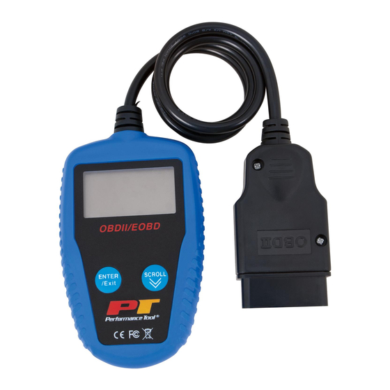
PRODUCT INFORMATION Tool Description 1. LCD DISPLAY - Indicates test results. It is a backlit 2-line display with 8 characters on each line. 2. ENTER/EXIT BUTTON - Confirms a selection (or action) from a menu list, or returns to the main menu. 3. - Page 9 Setup The code reader allows you to make the following adjustments and settings: 1) Language: Selects desired language. 2) Unit of measure: Sets the unit of measure to English or Metric. 3) Contrast adjustment: Adjusts the contrast of the LCD display. •...
-
Page 10: Vehicle Coverage
Contrast Adjustment System Setup 1) From System Setup menu, use SCROLL button ============================3/4 to select Contrast, and press ENTER/EXIT button. 1) Language 2) Unit of Measure u 3) Contrast 2) From Contrast menu, use SCROLL button to 4) Exit adjust contrast. Contrast 3) Press ENTER/EXIT button to save your ==============================... -
Page 11: Operating Instructions
OPERATING INSTRUCTIONS 1) Turn the ignition off. 2) Locate the vehicle’s 16-pin Data Link Connector (DLC). 3) Plug into the OBDII cable to the vehicle’s DLC. 4) Turn the ignition on. Engine can be off or running. 5) Press ENTER/EXIT button to enter Diagnostic Menu. A sequence of messages displaying the OBD2 protocols will be observed on the display until the vehicle protocol is detected. -
Page 12: Erasing Codes
• The control module number, sequence of the DTCs, total number of codes detected and type of codes (Generic or Manufacturer specific, Stored or Pending codes) will be observed on the upper right hand corner of the display. 3) If more than one DTC is found, use SCROLL button, as necessary, until all the codes have been shown up. -
Page 13: Retrieving I/M Readiness Status
Viewing Freeze frame Data Diagnostic Menu 1) To view freeze frame, use SCROLL button ============================3/6 to select View Freeze Frame from Diagnostic Menu 1) Read Codes 2) Erase Codes and press ENTER/EXIT button. u 3) View Freeze Frame • If more than one module is detected, you will 4) I/M Readiness be prompted to select a module before test. - Page 14 1) Use SCROLL button to select I/M Readiness from Diagnostic Menu Diagnostic Menu and press ENTER/EXIT. ============================4/6 • If more than one module is detected, you will 1) Read Codes be prompted to select a module before test. 2) Erase Codes 3) View Freeze Frame •...
- Page 15 1) Use SCROLL button to select Vehicle Info. from Diagnostic Menu Diagnostic Menu and press ENTER/EXIT button. ============================5/6 u 5) I/M Readiness 2) Wait a few seconds or press ENTER/EXIT 6) Exit button to continue. • If the vehicle does not support this mode, a “The selected mode is not supported!”...
-
Page 16: Diagnostic Trouble Code (Dtc) Definitions
DIAGNOSTIC TROUBLE CODE (DTC) DEFINITIONS The following Diagnostic Trouble Code Definitions lists provide only Generic Diagnostic Trouble Codes. For Manufacturer Specific Diagnostic Trouble Code Definitions, consult the vehicle’s service manual. CAUTION: Parts or components should not be replaced based on only a DTC without first consulting the vehicle service manual for more information on possible causes of the fault as well as required testing procedures. - Page 17 OBDII Generic DTC Definitions P0023 Camshaft Position Actuator B - Bank 2 Circuit Malfunction P0024 Camshaft Position Actuator B - Bank 2 Timing Over-Advanced P0025 Camshaft Position Actuator B - Bank 2 Timing Over-Retarded P0026 Intake Valve-Bank 1 Control Solenoid CKT Range/Performance P0027 Exhaust Valve-Bank 1 Control Solenoid CKT Range/Performance P0028...
- Page 18 OBDII Generic DTC Definitions P0059 HO2S Bank 2 Sensor 1 Heater Resistance P0060 HO2S Bank 2 Sensor 2 Heater Resistance P0061 HO2S Bank 2 Sensor 3 Heater Resistance P0062 HO2S Bank 2 Sensor 3 Heater Circuit P0063 HO2S Bank 2 Sensor 3 Heater Circuit Low P0064 HO2S Bank 2 Sensor 3 Heater Circuit High P0065...
- Page 19 OBDII Generic DTC Definitions P0095 IAT Sensor 2 Circuit P0096 IAT Sensor 2 CKT Range/Performance P0097 IAT Sensor 2 Circuit Low P0098 IAT Sensor 2 Circuit High P0099 IAT Sensor 2 CKT Intermittent P0100 MAF or VAF A Circuit Malfunction P0101 MAF or VAF A Circuit Range/Performance P0102...
- Page 20 OBDII Generic DTC Definitions P0131 O2 Sensor Circuit Low Volts (Bank 1 Sensor 1) P0132 O2 Sensor Circuit High Volts (Bank 1 Sensor 1) P0133 O2 Sensor CKT Slow Response (Bank 1 Sensor 1) P0134 O2 Sensor CKT No Activity (Bank 1 Sensor 1) P0135 O2 Sensor Heater Circuit Malfunction (Bank 1 Sensor 1) P0136...
- Page 21 OBDII Generic DTC Definitions P0167 O2 Sensor Heater Circuit Malfunction (Bank 2 Sensor 3) P0168 Engine Fuel Temperature Too High P0169 Fuel Composition Incorrect P0170 Fuel Trim Malfunction (Bank 1) P0171 System Too Lean (Bank 1) P0172 System Too Rich (Bank 1) P0173 Fuel Trim Malfunction (Bank 2) P0174...
- Page 22 OBDII Generic DTC Definitions P0203 Injector Circuit Open Cylinder 3 P0204 Injector Circuit Open Cylinder 4 P0205 Injector Circuit Open Cylinder 5 P0206 Injector Circuit Open Cylinder 6 P0207 Injector Circuit Open Cylinder 7 P0208 Injector Circuit Open Cylinder 8 P0209 Injector Circuit Open Cylinder 9 P0210...
- Page 23 OBDII Generic DTC Definitions P0239 Turbo/Super Boost Sensor B Circuit Malfunction P0240 Turbo/Super Boost Sensor B CKT Range/Performance P0241 Turbo/Super Boost Sensor B Circuit Low Input P0242 Turbo/Super Boost Sensor B Circuit High Input P0243 Turbo/Sup Wastegate Solenoid A Malfunction P0244 Turbo/Sup Wastegate Solenoid A Range/Performance P0245...
- Page 24 OBDII Generic DTC Definitions P0273 Cylinder 5 Injector Control Circuit Low P0274 Cylinder 5 Injector Control Circuit High P0275 Cylinder 5 Contribution Balance Fault P0276 Cylinder 6 Injector Control Circuit Low P0277 Cylinder 6 Injector Control Circuit High P0278 Cylinder 6 Contribution Balance Fault P0279 Cylinder 7 Injector Control Circuit Low P0280...
- Page 25 OBDII Generic DTC Definitions P0309 Cylinder 9 Misfire Detected P0310 Cylinder 10 Misfire Detected P0311 Cylinder 11 Misfire Detected P0312 Cylinder 12 Misfire Detected P0313 Misfire Detected Low Fuel Level P0314 Misfire Detected Cyl. not Specific P0315 Crankshaft Position System Variation Not Learned P0316 Misfire Detected 1st 1000 Revs.
- Page 26 OBDII Generic DTC Definitions P0345 Camshaft Position Sensor A - Bank 2 Circuit Malfunction P0346 Camshaft Position Sensor A - Bank 2 CKT Range/Performance P0347 Camshaft Position Sensor A - Bank 2 Circuit Low Input P0348 Camshaft Position Sensor A - Bank 2 Circuit High Input P0349 Camshaft Position Sensor A - Bank 2 CKT Intermittent P0350...
- Page 27 OBDII Generic DTC Definitions P0382 Glow Plug/Heater CKT B Malfunction P0383 Glow Plug Module Control Circuit Low P0384 Glow Plug Module Control Circuit High P0385 Crankshaft Position Sensor B Circuit Malfunction P0386 Crankshaft Position Sensor B CKT Range/Performance P0387 Crankshaft Position Sensor B Circuit Low Input P0388 Crankshaft Position Sensor B Circuit High Input P0389...
- Page 28 OBDII Generic DTC Definitions P0423 Heated Catalyst Below Threshold (Bank 1) P0424 Heated Catalyst Temp Below Threshold (Bank 1) P0425 Catalyst Temp. Sensor (Bank 1 Sensor 1) P0426 Catalyst Temp. Sensor Performance (Bank 1 Sensor 1) P0427 Catalyst Temp. Sensor Circuit Low (Bank 1 Sensor 1) P0428 Catalyst Temp.
- Page 29 OBDII Generic DTC Definitions P0459 EVAP System Canister Purge Sol Circuit High P0460 Fuel Level Sensor A Circuit Malfunction P0461 Fuel Level Sensor A CKT Range/Performance P0462 Fuel Level Sensor A Circuit Low Input P0463 Fuel Level Sensor A Circuit High Input P0464 Fuel Level Sensor A CKT Intermittent P0465...
- Page 30 OBDII Generic DTC Definitions P0495 Fan Speed High P0496 EVAP Emission High Purge Flow Fault P0497 EVAP Emission Low Purge Flow Fault P0498 EVAP Emission Vent Vlv/Sol Malf Circuit Low P0499 EVAP Emission Vent Vlv/Sol Malf Circuit High P0500 Vehicle Speed Sensor A Malfunction P0501 Vehicle Speed Sensor A Range/Performance P0502...
- Page 31 OBDII Generic DTC Definitions P0531 A/C Refrigerant Pressure Sensor A CKT Range/Performance P0532 A/C Refrigerant Pressure Sensor A Circuit Low Input P0533 A/C Refrigerant Pressure Sensor A Circuit High Input P0534 A/C Refrigerant Charge Loss P0535 A/C Evaporator Temperature Sensor Circuit P0536 A/C Evaporator Temperature Sensor CKT Range/Performance P0537...
- Page 32 OBDII Generic DTC Definitions P0567 Cruise Control Resume Signal Malfunction P0568 Cruise Control Set Signal Malfunction P0569 Cruise Control Coast Signal Malfunction P0570 Cruise Control Acceleration Signal Error P0571 Brake Switch A Circuit Malfunction P0572 Brake Switch A Circuit Low Input P0573 Brake Switch A Circuit High Input P0574...
- Page 33 OBDII Generic DTC Definitions P0603 PCM Keep Alive Memory (KAM) Error P0604 PCM Random Access Memory (RAM) Error P0605 PCM Read Only Memory (ROM) Error P0606 PCM Processor Fault P0607 Control Module Performance P0608 Control Module VSS Output A Malfunction P0609 Control Module VSS Output B Malfunction P0610...
- Page 34 OBDII Generic DTC Definitions P0639 Throttle Actuator Range/Performance (Bank 2) P0640 Intake Air Heater Control Circuit P0641 Sensor A Reference Voltage Circuit Open P0642 Sensor A Reference Voltage Circuit Low P0643 Sensor A Reference Voltage Circuit High P0644 Driver Display Serial Communication Link P0645 A/C Clutch Relay Control Circuit P0646...
- Page 35 OBDII Generic DTC Definitions P0675 Glow Plug/Heater Cylinder 5 P0676 Glow Plug/Heater Cylinder 6 P0677 Glow Plug/Heater Cylinder 7 P0678 Glow Plug/Heater Cylinder 8 P0679 Glow Plug/Heater Cylinder 9 P0680 Glow Plug/Heater Cylinder 10 P0681 Glow Plug/Heater Cylinder 11 P0682 Glow Plug/Heater Cylinder 12 P0683 Glow Plug/Heater Module Communication Problem...
- Page 36 OBDII Generic DTC Definitions P0711 Trans Fluid Temp Sensor A CKT Range/Performance P0712 Trans Fluid Temp Sensor A Circuit Low Input P0713 Trans Fluid Temp Sensor A Circuit High Input P0714 Trans Fluid Temp Sensor A CKT Intermittent P0715 Input/Turbine Speed Sensor A Circuit Malfunction P0716 Input/Turbine Speed Sensor A CKT Range/Performance P0717...
- Page 37 OBDII Generic DTC Definitions P0747 Pres Control Sol. A Circuit Stuck On P0748 Pres Control Sol. A Circuit Electrical P0749 Pres Control Sol. A CKT Intermittent P0750 Shift Solenoid A Malfunction P0751 Shift Solenoid A CKT Performance Or Stuck Off P0752 Shift Solenoid A Circuit Stuck On P0753...
- Page 38 OBDII Generic DTC Definitions P0783 3-4 Shift Malfunction P0784 4-5 Shift Malfunction P0785 Shift/Timing Solenoid Malfunction P0786 Shift/Timing Solenoid Range/Performance P0787 Shift/Timing Solenoid Low P0788 Shift/Timing Solenoid High P0789 Shift/Timing Solenoid Intermittent Ckt P0790 Normal/Performance Switch Circuit Malfunction P0791 Intermediate Shaft Speed Sensor A Circuit P0792 Intermediate Shaft Speed Sensor A Circuit Range/Performance P0793...
- Page 39 OBDII Generic DTC Definitions P0819 Up/Down Shift SW Transmission Range Correlation P0820 Gear Lever X-Y Sensor Circuit P0821 Gear Lever X Sensor Circuit P0822 Gear Lever Y Sensor Circuit P0823 Gear Lever X Sensor Circuit Intermittent Ckt P0824 Gear Lever Y Sensor Circuit Intermittent Ckt P0825 Gear Lever Push/Pull Switch (Shift Anticipate) P0826...
- Page 40 OBDII Generic DTC Definitions P0855 Drive Switch Circuit High Input P0856 Traction Control Input Signal P0857 Traction Control Input Signal Range/Performance P0858 Traction Control Input Signal Low P0859 Traction Control Input Signal High P0860 Gear Shift Module Communications Circuit P0861 Gear Shift Module Communications Circuit Low P0862 Gear Shift Module Communications Circuit High...
- Page 41 OBDII Generic DTC Definitions P0891 TCM Power Relay Sense Circuit High P0892 TCM Power Relay Sense CKT Intermittent P0893 Multiple Gears Engaged P0894 Transmission Comp. Slipping P0895 Shift Time Too Short P0896 Shift Time Too Long P0897 Transmission Fluid Deteriorated P0898 Transmission Ctrl.
- Page 42 OBDII Generic DTC Definitions P0927 Gear Shift Reverse Actuator Circuit High P0928 Gear Shift Lock Solenoid Ctrl Circuit Open P0929 Gear Shift Lock Solenoid Ctrl CKT Range/Performance P0930 Gear Shift Lock Solenoid Ctrl Circuit Low P0931 Gear Shift Lock Solenoid Ctrl Circuit High P0932 Hydraulic Pressure Sensor Circuit P0933...
- Page 43 OBDII Generic DTC Definitions P0963 Pressure Control Solenoid A Control Circuit High P0964 Pressure Control Solenoid B Control Circuit Open P0965 Pressure Control Solenoid B Control CKT Range/Performance P0966 Pressure Control Solenoid B Control Circuit Low P0967 Pressure Control Solenoid B Control Circuit High P0968 Pressure Control Solenoid C Control Circuit Open P0969...
- Page 44 90 days from the date of purchase, provided that product is returned to place of purchase immediately after discovery of defect. After 90 days and up to one year from date of purchase, PERFORMANCE TOOL® will replace at no charge any parts which our examination shall disclose to be defective and under warranty.
Need help?
Do you have a question about the W2976 and is the answer not in the manual?
Questions and answers
Where do the 8 wires go when there are 16 pin options ? I need a diagram of what color goes where to fix it