Table of Contents
Advertisement
Quick Links
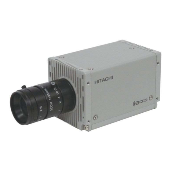
3CCD color camera
HV-F203SCL
Operation Manual
Thank you for purchase this fine Hitachi Kokusai Electric CCD camera.
Before using the camera, please read this operation manual carefully.
There is a possibility that the revised edition is exhibited on web.
Please confirm by web shown in an Installation Guide.
Hitachi Kokusai Electric Inc.
RoHS Compliant
These products comply with the requirement of the RoHS (Restriction of the
use of Certain Hazardous Substances in Electrical and electronic Equipment)
Directive 2002/95/EC.
Preliminary version
Version in Sep, 2017
Advertisement
Table of Contents

Related Manuals for Hitachi Kokusai Electric HV-F203SCL

Summary of Contents for Hitachi Kokusai Electric HV-F203SCL
- Page 1 3CCD color camera HV-F203SCL Operation Manual Thank you for purchase this fine Hitachi Kokusai Electric CCD camera. Before using the camera, please read this operation manual carefully. There is a possibility that the revised edition is exhibited on web. Please confirm by web shown in an Installation Guide.
- Page 2 IMPORTANT SAFETY INSTRUCTIONS 1. Read Instructions All the safety and operating instructions should be read before the product is operated. 2. Retain Instructions The safety and operating instructions should be retained for future reference. 3. Heed Warnings All warnings on the product and the operating instructions should be adhered to. 4.
- Page 3 16. Object and Liquid Entry Never push objects of any kind into this product through openings as they may touch dangerous voltage points or short-out parts that could result in a fire or electric shock. Never spill liquid of any kind on the product. 17.
- Page 4 WICHTIGE SICHERHEITS ANWEISUNGEN 1. Alle Anweisungen lesen Vor Betrieb des Erzeugnisses sollten alle Sicherheits-und Bedienungsanleitungen gelesen werden. 2. Die Anweisungen aufbewahren Die Sicherheits-und Bedienungsanleitungen sollten fünftigen Bezug aufbewahrt werden. 3. Warnungen beachten Die Warnungen auf dem Erzeugnis und in den Bedienungsanleitungen solten beachtet werden. 4.
- Page 5 16. Eindringen von Fremdkörpern und Flüssigkeit Niemals Objekte irgendwelcher Art durch die Öffnungen in das Gerät schieben, da diese unter hoher Spannung stehende Teile berühren oder kurzschließen können, wodurch es zu Feuer oder elektrischem Schlag kommen kann. Niemals Flüssigkeiten irgendwelcher Art auf das Erzeugnis verschütten. 17.
- Page 6 MISES EN GARDE IMPORTANTES 1. Lire les instructions Lire toutes les instructions de sécurité et de fonctionnement avant de faire fonctionner l’appareil. 2. Conserver ces instructions Conserver les instructions de sécurité et de fonctionnement á des fins de référence ultérieure. 3.
- Page 7 16. Pénétration d’objets et de liquides Ne jamais enfoncer d’objets d’aucune sorte dans les ouvertures de l’appareil car ils pourraient toucher des points de tension dangereuse ou court-circuiter des piéces, ce qui pourrait provoquer un feu ou un choc électrique. Ne jamais renverser de liquide d’aucune sorte sur l’appareil.
- Page 8 IMPORTANT NOTICE For Canada This product does not exceed the class A/class These products have been tested and found to B limits for radio noise emissions from digital comply with the limits for a Class A digital device, apparatus as set out in the radio interference pursuant to Part 15 of the FCC Rules.
- Page 9 China RoHS The following statement is related to the regulation on “ Measures for the Administration of the control of Pollution by Electronic Information Products “ , known as “ China RoHS “. The table shows contained Hazardous Substances in this camera. 说明书(环境方面:补充资料)...
- Page 10 Phenomena inherent to CCD imaging device The following phenomena are inherent to a charge coupled device imaging element and do not indicate malfunction. 1) Smear and blooming Vertical bands are visible when a strong light enters the scene. Adjust the camera aiming direction carefully to avoid strong direct or reflected light.
- Page 11 Operating considerations Notes to users 1. Important safety notes ・ Please supply the direct current 12V of the camera input power supply within the range of 11 to 13V ・ Time will be needed for about four seconds by the time the camera works normally after turning on the power supply. ・...
-
Page 12: Table Of Contents
Table of Contents Overview ..................................3 Standard composition ..............................3 Features ..................................3 System example ................................. 3 Section name and functions ............................4 Camera mounting (Attention Hot!) .......................... 4 Lens ..................................... 4 Connector ..................................5 Functions and operations ............................7 TRIGGER : Setting about external trigger ...................... - Page 13 13.1 Normal mode (MODE:OFF) ........................... 30 Fixed shutter mode .............................. 32 13.2 ONE trigger mode ..............................33 13.3 Input / Output signal ............................34 Spectral response ..............................34 Specifications ................................ 35 Dimensions ................................36...
-
Page 14: Overview
Overview HV-F203SCL is high precision 3CCD progressive scan color camera, which has single chip digital processing LSI, a C mount prism, 1/1.8 inch 2M pixels square CCD and CameraLink interface. Standard composition Check when unpacking Camera Installation guide Plug for DC IN/SYNC connector (HR10A-10P-12S) -
Page 15: Section Name And Functions
Section name and functions Camera / Tripod adaptor mounting screw holes CameraLink connectors Use for digital video output and camera control signal Lens mount input/output signal. (C mount) Pilot lamp It lights up when power supply. Camera / Tripod adaptor mounting screw holes DC IN/SYNC connector Use for DC+12V power or external... -
Page 16: Connector
Connector 1. CameraLink connector (a) Interrelation between number of DATA bit and number of used conndecor Number of Data bits D.OUT1 D.OUT2 24bit (R: 8bit G: 8bit B: 8bit) O: Use 30bit (R: 10bit G: 10bit B: 10bit) -: Not use 36bit (R: 12bit G: 12bit B: 12bit) (b) Signal connection of DIGITAL OUT connector D.OUT1... - Page 17 2. DCIN/SYNC connector PIN NO. Signal PIN NO. Signal GND (+12V) TRIG +12V N.C. N.C. FLASH / VD OUT N.C. N.C. Connector (camera side) : SANWOO SHN-10-12 (RPCB) or equivalent Plug (matching cable plug : HR10A-10P-12S(01) HIROSE or equivalent (Note) Please do not unplug and insert cable (camera cable) with a power supplied to a camera. Install clamp filter(ZCAT 2035-0930A: TDK) at both ends (camera and video processor ends) in the CE marking region.
-
Page 18: Functions And Operations
Functions and operations Various mode setup and adjustment of HV-F203SCL are performed by the remote control via CameraLink. Operation and adjustment way of function utilized are described below. See "Remote control" (page 14 ~ ) and "Command list" (page 21 ~ ) about communication method of each command. -
Page 19: Gain Level : Setting Of Electrical Sensitivity
-AES MODE- : selects a control mode of AES (Automatic electronic shutter). OFF (Factory setting) : Not perform AES (using manual setting of OFF/PRESET/VARIABLE). : An electronic shutter is controlled automatically so that the brightness of the output image will be practical level. -AES MIN- : setting to shortest speed limit of an AES. -
Page 20: Knee : Setting Of Knee
9.7 KNEE : Setting of KNEE -MODE- : Selection of mode OFF (Factory setting) : Not perform knee. : Knee function provides natural gradation in bright portions. -KNEE POINT- : Adjust knee point 0 (Factory setting) to 32 : Setting value toward 0 side increase start level of knee and 32 side decrease start level of knee. -KNEE SLOPE- : Adjust knee slope 0 (Factory setting) to 159 : Setting value toward 0 side intensify effective of knee and 159 side weaken effective of knee. -
Page 21: Masking : Setting Of 6 Vector Independent Making
9.11 MASKING : Setting of 6 vector independent making (primary color R G B and complementary color Ye Cy Mg saturation and hue can be separately varied). A figure is showing the masking effects on the color vector. ===> -MODE- : Selection of mode OFF (Factory setting) : Not use masking functions. -
Page 22: Paint Black : Setting Of Paint Black (Color Level Of R, G, And B Can Be Separately Varied)
9.12 PAINT BLACK : Setting of paint black (color level of R, G, and B can be separately varied). -MODE- : Selection of mode OFF (Factory setting) : Not use paint black functions. : Use paint black functions. -RED- : Adjust red color level 0 (Factory setting) to 127 : Adjust red color level in 128 steps. -
Page 23: White Spot : Setting Of White Spot Correction
9.17 WHITE SPOT : Setting of white spot correction -MODE - : Selection of mode : Not perform white spot correction. ON (Power On status) : Perform white spot correction. (This status follows a power supply start of a camera, and is setting to ON.) -THRESHOLD R- : Threshold of white spot correction for Red CCD 1 to 99 : Set threshold value for Red CCD by output value from 1% to 99%. -
Page 24: Binning : Setting Of Vertical Pixel Mix
9.18 BINNING : Setting of Vertical Pixel Mix OFF (Factory setting) : Not perform vertical pixel mix. : Vertical pixel mix doing that make approximately double frame rate. 9.19 PARTIAL : Setting for Partial Scan -MODE - : Selection of mode : Not perform partial scan. -
Page 25: Remote Control
Remote control 1. Comms* specifications ・Control system : Start-stop synchronization system ・Transmission rate : 115200 bps ・Data length : 8 bit ・Star bit : 1 bit ・Stop bit : 1 bit ・Parity : None ・Bit transfer : LSB first *Comms: Communications 2. - Page 26 (1) Transmission from master (normal process) HITACH Transmit data (STX-ETX.SUM) 3CCD ACK code (06H) Slave (Camera) Master (Machine) ① Master sends data to slave. ② Slave acknowledges receipt of data by again returning ACK to master and end the handshake. (2)...
- Page 27 (3) Processing at the time of SUM value error occurred Illegal command SUM value (STX-ETX.??) HITACH NACK code (15H) 3CCD Slave (Camera) Master (Machine) ① Transmitted to the slave the command of illegal SUM value from the master. ② If the SUM value is illegal received command, the slave discards the contents of the received, send "NAK"...
- Page 28 (5) Data frame error (Master transmission) Send data (ASCII code) HITACH 3 second elapse Send data (ASCII code) 3CCD 3 second Slave elapse (Camera) Send data (ASCII code) Master (Machine) 3 second elapse Send data (ASCII code) ① Master sends data. ②...
- Page 29 (6) Transmission frame error (Master receive) Read command (ASCII code) HITACH ACK code (06H) 3CCD Read data (ASCII code) Slave 3 second (Camera) elapse Read data (ASCII code) Master (Machine) 3 second elapse Read data (ASCII code) 3 second elapse Read data (ASCII code) ①...
- Page 30 2 byte (ASCII code) Used for EEPROM write (0: write absent, 1: write present). ・ID No. : Camera peculiar ID. HV-F203SCL has (FFH). 2 byte (ASCII code) ・Area address : Classification of Send data (01H) and Read command (81H). 2 byte (ASCII code) ・Relative No.
- Page 31 (2) Read (receive) data (slave to master) (a) Command data are converted into ASCII code and transmitted. (b) Comms byte quantity is 10. (c) Comms data format (transmission sequence) S T X Text data E T X S U M 1 byte 2 byte 1 byte...
-
Page 32: Command List
Command list 11.1 Send data (setting command, Note: 1 to 7 and SUM need to be transformed into ASCII code) Item AREA RELATIVE STATUS ID NO. DATA ADDRESS [02] [03] MODE FIXED [02] [03] 1TRIG [02] [03] TRIGGER POSITIVE [02] [03] POLARITY NEGATIVE... - Page 33 Item AREA RELATIVE STATUS ID NO. DATA ADDRESS [02] [03] MODE ON1(Normal) [02] [03] GAMMA [02] [03] (S Gamma) MIN (0) [02] [03] LEVEL MAX (255) [02] [03] [02] [03] MODE [02] [03] MIN (0) [02] [03] KNEE POINT KNEE MAX (32) [02] [03]...
- Page 34 Item AREA RELATIVE STATUS ID NO. DATA ADDRESS [02] [03] MODE [02] [03] MIN (0) [02] [03] RED-SATURATION MAX (255) [02] [03] MIN (0) [02] [03] RED-HUE MAX (255) [02] [03] MIN (0) [02] [03] CYAN-SATURATION MAX (255) [02] [03] MIN (0) [02] [03]...
- Page 35 Item AREA RELATIVE STATUS ID NO. DATA ADDRESS [02] [03] [02] [03] 24BIT [02] [03] DATA BIT 30BIT [02] [03] 36BIT [02] [03] [02] [03] SIGNAL FLASH OUT [02] [03] OUTPUT [02] [03] POSITIVE [02] [03] POLARITY NEGATIVE [02] [03] [02] [03] MODE...
-
Page 36: Read-Out Command
11.2 Read-out command (Note: 1 to 7 and SUM need to be transformed into ASCII code) Item AREA RELATIVE STATUS ID NO. DATA ADDRESS MODE [02] [03] TRIGGER POLARITY [02] [03] SOURCE [02] [03] PRESET [02] [03] VARIABLE VALUE (2Byte) [02] [03] SHUTTER... - Page 37 Item AREA RELATIVE STATUS ID NO. DATA ADDRESS MODE [02] [03] [02] [03] PAINT BLACK GREEN [02] [03] BLUE [02] [03] MODE [02] [03] WHITE SHADING ADJUST [02] [03] [02] [03] DATA BIT [02] [03] SIGNAL [02] [03] OUTPUT POLARITY [02] [03] MODE...
-
Page 38: Cameralink Output Timing Chart
CameraLink output timing chart 12.1 Horizontal timing 1920 clk 1600 clk VIDEO Active Picture LVAL 1CLK= 13.889 ns 12.2 Transmitter LVDS output pulse position measurement (1) Base Configuration (a) 24bit D.OUT 1 13.889ns (72.0000MHz) CLKX Previous Cycle Next Cycle R7-1 R6-1 N.U. - Page 39 (2) Medium Configuration (a) 30bit D.OUT 1 13.889ns (72.0000MHz) CLKX Previous Cycle Next Cycle R7-1 R6-1 N.U. N.U. N.U. B3-1 B2-1 N.U. FVAL LVAL N.U. R9-1 N.U. N.U. R1-1 R0-1 N.U.: Not used D.OUT 2 13.889ns (72.0000MHz) CLKY Previous Cycle Next Cycle N.U.
- Page 40 (b) 36bit D.OUT 1 13.889ns (72.0000MHz) CLKX Previous Cycle Next Cycle R7-1 R6-1 N.U. B3-1 B2-1 N.U. FVAL LVAL R10-1 R9-1 R1-1 R0-1 N.U.: Not used D.OUT 2 13.889ns (72.0000MHz) CLKY Previous Cycle Next Cycle N.U. N.U. N.U. N.U. N.U. N.U.
-
Page 41: Trigger Operation And Timing Chart
Trigger operation and timing chart 13.1 Normal mode (MODE:OFF) Shutter time (Camera setting value) Shutter time Data output ① ② FVAL ③ (10pin-OUT) μs 1H = 26.7 1.1 Shutter time ≦ ① Partial scan OFF Partial scan ON ( is Ceiling function ) BinningVertical BinningVertical BinningVertical OFF... - Page 42 The following graph is the relationship of the partial scan and "capture width", "frame rate". partial_binning (SensorArea) partial_binning (OutputLine) partial (SensorArea &OutputLine) 200 225 250 275 300 350 400 450 500 550 600 700 800 900 1000 1100 1200 Vertical Line (SensorArea & OutputLine) [H] Equation below is the formula for the "total number of lines by capture width (the decimal point is truncated)"...
-
Page 43: Fixed Shutter Mode
13.2 Fixed shutter mode When external trigger signal is POSITIVE (high active), after the trigger signal rise, exposure is start. The exposure time is set by the camera electronic shutter speed. The video output is obtained immediately after the end of fixed exposure. More than ①... -
Page 44: One Trigger Mode
13.3 ONE trigger mode When external trigger signal is POSITIVE (high active), after the trigger signal rise, exposure is start. At the trigger signal falling edge, the video data are transmitted. More than ① High Trigger input(POSI) More than 10μs Shutter time Shutter time (Camera setting value) -
Page 45: Input / Output Signal
14. Input / Output signal 1. Input signal The level of the trigger signal input to HV-F203SCL is as follows. (1) Input from CameraLink cable LVDS level. (2) Input from 12-pin connector 5Vp-p ± 0.5V 2. Output signal The level of the VD/FLASH signal output from HV-F203SCL is as follows. -
Page 46: Specifications
Specifications Specifications of HV-F203SCL are showing. Optical system 1/1.8-inch F1.9 prism with IR cut filter Imaging device 1/1.8-inch interline CCD Total pixels 1688 (H) x 1248 (V) Effective pixels 1636 (H) x 1220 (V) Active pixels 1600 (H) x 1200 (V) Pixel pitch 4.4μ... -
Page 47: Dimensions
Dimensions... - Page 48 São Paulo, 01419-001, SP –Brazil Phone: +55(11)3541-3244, Fax: +55(11)3541-2425 URL: http://www.hitachi-linear.com.br/ Hitachi Kokusai Electric Turkey Elektronik Ürünleri Sanayi ve Ticaret A.Ş. Hitachi Kokusai Electric Turkey Yayıncılık Sistemleri A.Ş. Office : Istanbul Endustri ve Ticaret Serbest Bolgesi Akif Kopuz Cad. No.3,...
Need help?
Do you have a question about the HV-F203SCL and is the answer not in the manual?
Questions and answers