Table of Contents
Advertisement
Quick Links
Advertisement
Table of Contents

Related Manuals for Xylem Goulds Marlow e-580 Series


Summary of Contents for Xylem Goulds Marlow e-580 Series
- Page 1 INSTRUCTION MANUAL P2002885 Rev B Marlow Series e-580...
-
Page 3: Table Of Contents
Table of Contents Table of Contents 1 Introduction and Safety......................3 1.1 Introduction.......................... 3 1.2 Safety............................. 3 1.2.1 Safety terminology and symbols.................3 1.2.2 Safety instruction decals....................4 1.2.3 User safety........................5 1.2.4 Protecting the environment..................6 2 Transportation and Storage...................... 7 2.1 Examine the delivery......................7 2.1.1 Examine the package.................... - Page 4 Table of Contents 6.4.2 Assemble the single mechanical seal (e-580-S)............22 6.4.3 Install the impeller...................... 23 6.4.4 Reinstall the pump assembly..................23 6.4.5 Screw torque values....................24 6.4.6 Dealer servicing ......................24 7 Product warranty........................25 Marlow Series e-580 INSTRUCTION MANUAL...
-
Page 5: Introduction And Safety
This includes any modification to the equipment or use of parts not provided by Xylem. If there is a question regarding the intended use of the equipment, please contact a Xylem representative before proceeding. -
Page 6: Safety Instruction Decals
1 Introduction and Safety Hazard levels Hazard level Indication A hazardous situation which, if not avoided, will result in DANGER: death or serious injury A hazardous situation which, if not avoided, could result WARNING: in death or serious injury A hazardous situation which, if not avoided, could result CAUTION: in minor or moderate injury Notices are used when there is a risk of equipment... -
Page 7: User Safety
1 Introduction and Safety All series e-580 Pumps All series e-580 with optional ITSC/IT EYEBOLTS OR LIFTING LUGS IF PROVIDED ARE DO NOT RUN PUMP DRY. ROTATING COMPONENTS FOR LIFTING ONLY THE SEAL DAMAGE MAY OCCUR. WARNING COMPONENTS TO WHICH DISCONNECT AND LOCK INSPECT PUMP SEAL THEY ARE ATTACHED. -
Page 8: Protecting The Environment
• Clean-up of spills Exceptional sites CAUTION: Radiation Hazard Do NOT send the product to Xylem if it has been exposed to nuclear radiation, unless Xylem has been informed and appropriate actions have been agreed upon. Recycling guidelines Always follow local laws and regulations regarding recycling. -
Page 9: Transportation And Storage
2 Transportation and Storage 2 Transportation and Storage 2.1 Examine the delivery 2.1.1 Examine the package 1. Examine the package for damaged or missing items upon delivery. 2. Record any damaged or missing items on the receipt and freight bill. 3. -
Page 10: Long-Term Storage
2 Transportation and Storage Series e-580 Series e-580 with optional ITSC/IT Figure 1: Proper lifting method 2.3 Long-term storage If the unit is stored for more than 6 months, these requirements apply: • Store in a covered and dry location. •... -
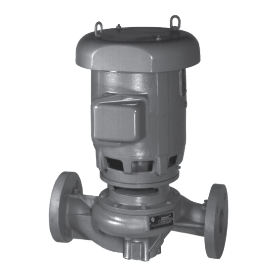
Page 11: Product Description
3 Product Description 3 Product Description 3.1 General description The pump is a centrifugal, in-line, close-coupled pump. These features make the pump easy to install, operate, and service: • High efficiency • Rugged stainless steel-fitted construction • Horizontal or vertical in-line mounting Intended applications WARNING: This product can expose you to chemicals including Lead, which is known to the State of... - Page 12 3 Product Description systems, cooling is accomplished by inserting a small heat exchanger in the flush line to cool the seal flushing fluid. 3. Flush-line filters and sediment separators are available on request. 4. Use a standard seal on closed or open systems that are relatively free of dirt and/or other abrasive particles.
-
Page 13: Installation
(See the nameplate on the drive unit to select properly-sized overloads.) NOTICE: Supervision by an authorized Xylem representative is recommended to ensure proper installation. Failure to do so may result in equipment damage or decreased performance. Evaluate the installation in order to determine that the Net Positive Suction Head Available... -
Page 14: Piping Checklist
4 Installation Guideline Explanation/comment Keep the pump as close to the liquid source as practically This minimizes the friction loss and keeps the suction possible. piping as short as possible. If the pump is not on a closed system, locate the pump so that the fewest number of bends or elbows in the suction pipe are needed. -
Page 15: Typical Pump Installation
4 Installation Check Explanation/comment Checked Check that the suction or discharge lines are not forced into position. Check that fittings for absorbing expansion are This helps to avoid strain on the pump. installed in the system when considerable temperature changes are expected. Check that flexible piping is used on both the suction —... - Page 16 4 Installation Figure 4 Optional B&G Flange Supports can be used when rigid pump support to the floor or isolation base is required. The supports are installed on the back side of the pump flanges and have tapped holes to accept the flange bolting and have mounting holes in their bases for anchor bolts.
- Page 17 4 Installation Figure 8 e-580 pumps have a four bolt circle on the bottom of the volute to accept an ANSI/ASME flange that can be used with a connected pipe as a temporary pump support while the permanent pump piping or pump supports are being fitted to the pump. This support can only be used to handle the pump weight as it is not suitable resist loads in other directions.
-
Page 18: Commissioning, Startup, Operation, And Shutdown
5 Commissioning, Startup, Operation, and Shutdown 5 Commissioning, Startup, Operation, and Shutdown 5.1 Preparation for startup WARNING: • Failure to follow these precautions before you start the unit will lead to serious personal injury and equipment failure. • Do not operate the pump below the minimum rated flows or with the suction or discharge valves closed. -
Page 19: Prime The Pump
5 Commissioning, Startup, Operation, and Shutdown 5.2 Prime the pump CAUTION: Do not run the pump dry. Make sure that the pump body is full of liquid before startup. If the system does not automatically fill the pump body with liquid, then you must manually prime the pump. 1. -
Page 20: Shut Down The Pump
5 Commissioning, Startup, Operation, and Shutdown Operation at reduced capacity WARNING: Never operate any pumping system with a blocked suction and discharge. Operation, even for a brief period under these conditions, can cause confined pumped fluid to overheat, which results in a violent explosion. You must take all necessary measures to avoid this condition. -
Page 21: Maintenance
6 Maintenance 6 Maintenance 6.1 Lubrication The pump motor has been lubricated at the factory. Keep the motor properly lubricated in accordance with the motor manufacturer's instructions. 6.2 Disassembly 6.2.1 Disassembly precautions This manual clearly identifies accepted methods for disassembling units. These methods must be adhered to. -
Page 22: Remove The Impeller
When it is necessary to reduce the pump flow rate and generated head by trimming the impeller diameter, the following guidelines apply for stainless steel impellers: • Review the pump hydraulic selection data and consult your local Xylem representative to select the proper reduced diameter. -
Page 23: Pre-Assembly Inspections
6 Maintenance ØA ØB Figure 10: 5x5x7B impeller trim — 0.125 in. (3.17 mm) increments Hydraulic diameter, nominal, as Diameter at impeller inlet side Trim angle shown on selection curves shroud From maximum diameter 7 in. Use diameter from selection curves 0 degrees, no angle (177.8 mm) to 6.125 in. -
Page 24: Shaft And Sleeve Inspection
6 Maintenance 6.3.2 Shaft and sleeve inspection Inspection criteria Inspect the shaft and sleeve according to this criteria: • Thoroughly clean the shaft and sleeve. • Thoroughly clean the coverplate seal cavity. • Inspect the surface for damage such as pitting, corrosion, nicks, and scratches. Replace these parts if they are damaged. -
Page 25: Install The Impeller
6 Maintenance ID seal size Distance between collar and impeller end of the shaft sleeve 1-1/4 in. (3.175 cm) 1-13/32 in. (3.571 cm) 1-5/8 in. (4.128 cm) 1-1/4 in. (3.175 cm) 5. Assemble the coverplate onto the bracket. 6. Tighten the capscrews according to the Capscrew torque table. 7. -
Page 26: Screw Torque Values
6 Maintenance 6.4.5 Screw torque values Capscrew torque in ft-lb (Nm) Capscrew Head Capscrew diameter (in inches) type marking 5/16 7/16 SAE grade 6 (8) 13 (18) 25 (34) 38 (52) 60 (81) 120 (163) 190 (258) 210 (285) 300 (407) Brass and 4 (5) 10 (14) -
Page 27: Product Warranty
7 Product warranty 7 Product warranty Commercial warranty Warranty. For goods sold to commercial buyers, Seller warrants the goods sold to Buyer hereunder (with the exception of membranes, seals, gaskets, elastomer materials, coatings and other "wear parts" or consumables all of which are not warranted except as otherwise provided in the quotation or sales form) will be (i) be built in accordance with the specifications referred to in the quotation or sales form, if such specifications are expressly made a part of this Agreement, and (ii) free from defects in material and... - Page 28 7 Product warranty Limited consumer warranty Warranty. For goods sold for personal, family or household purposes, Seller warrants the goods purchased hereunder (with the exception of membranes, seals, gaskets, elastomer materials, coatings and other "wear parts" or consumables all of which are not warranted except as otherwise provided in the quotation or sales form) will be free from defects in material and workmanship for a period of one (1) year from the date of installation or eighteen (18) months from the product date code, whichever shall occur first, unless a...
- Page 29 7 Product warranty To make a warranty claim, check first with the dealer from whom you purchased the product or visit www.xyleminc.com for the name and location of the nearest dealer providing warranty service. Marlow Series e-580 INSTRUCTION MANUAL...
- Page 32 For more information on how Xylem can help you, go to www.xylem.com Xylem Inc. Visit our Web site for the latest version of this document and more information 8200 N.
Need help?
Do you have a question about the Goulds Marlow e-580 Series and is the answer not in the manual?
Questions and answers