Table of Contents
Advertisement
Quick Links
Advertisement
Table of Contents

Related Manuals for thomann STAIRVILLE PAR56 MKII RGBW


Summary of Contents for thomann STAIRVILLE PAR56 MKII RGBW
- Page 1 PAR56 MKII RGBW LED PAR user manual...
- Page 2 Musikhaus Thomann Thomann GmbH Hans-Thomann-Straße 1 96138 Burgebrach Germany Telephone: +49 (0) 9546 9223-0 E-mail: info@thomann.de Internet: www.thomann.de 27.05.2020, ID: 274638, 274643 (V3)
-
Page 3: Table Of Contents
Table of contents Table of contents General information..........................5 1.1 Further information........................... 6 1.2 Notational conventions........................7 1.3 Symbols and signal words....................... 7 Safety instructions..........................10 Features............................... 16 Installation..............................17 Starting up..............................21 Connections and operating elements................... 24 Operating..............................26 7.1 Starting up the device........................ - Page 4 Table of contents 7.6 Functions in 8-channel DMX mode................... 36 Technical specifications........................38 Plug and connection assignments....................40 Troubleshooting............................41 Cleaning............................... 43 Protecting the environment......................44 LED PAR...
-
Page 5: General Information
Our products and user manuals are subject to a process of continuous development. We there‐ fore reserve the right to make changes without notice. Please refer to the latest version of the user manual which is ready for download under www.thomann.de. PAR56 MKII RGBW... -
Page 6: Further Information
General information 1.1 Further information On our website (www.thomann.de) you will find lots of further information and details on the following points: Download This manual is also available as PDF file for you to download. Use the search function in the electronic version to find the topics of Keyword search interest for you quickly. -
Page 7: Notational Conventions
General information 1.2 Notational conventions This manual uses the following notational conventions: Letterings The letterings for connectors and controls are marked by square brackets and italics. Examples: [VOLUME] control, [Mono] button. Displays Texts and values displayed on the device are marked by quotation marks and italics. Examples: ‘24ch’... - Page 8 General information Signal word Meaning DANGER! This combination of symbol and signal word indicates an immediate dangerous situation that will result in death or serious injury if it is not avoided. WARNING! This combination of symbol and signal word indicates a pos‐ sible dangerous situation that can result in death or serious injury if it is not avoided.
- Page 9 General information Warning signs Type of danger Warning – suspended load. Warning – danger zone. PAR56 MKII RGBW...
-
Page 10: Safety Instructions
Safety instructions Safety instructions Intended use This device is intended for use as an electronic lighting effect by means of LED technology. The device is designed for professional use and is not suitable for use in households. Use the device only as described in this user manual. Any other use or use under other operating con‐ ditions is considered to be improper and may result in personal injury or property damage. - Page 11 Safety instructions Safety DANGER! Danger for children Ensure that plastic bags, packaging, etc. are disposed of properly and are not within reach of babies and young children. Choking hazard! Ensure that children do not detach any small parts (e.g. knobs or the like) from the unit.
- Page 12 Safety instructions DANGER! Electric shock caused by short-circuit Do not modify the mains cable or the plug. Failure to do so could result in electric shock/death or fire. If in doubt, seek advice from a registered electrician. WARNING! Eye damage caused by high light intensity Never look directly into the light source.
- Page 13 Safety instructions NOTICE! Risk of fire Do not block areas of ventilation. Do not install the device near any direct heat source. Keep the device away from naked flames. PAR56 MKII RGBW...
- Page 14 Safety instructions NOTICE! Operating conditions This device has been designed for indoor use only. To prevent damage, never expose the device to any liquid or moisture. Avoid direct sunlight, heavy dirt, and strong vibrations. Only operate the device within the ambient conditions specified in the chapter ‘Technical specifications’...
- Page 15 Safety instructions NOTICE! Power supply Before connecting the device, ensure that the input voltage (AC outlet) matches the voltage rating of the device and that the AC outlet is protected by a residual current circuit breaker. Failure to do so could result in damage to the device and possibly injure the user.
-
Page 16: Features
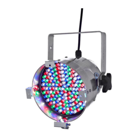
Features Features The LED-PAR is ideal for professional lighting applications, for example, at events, on rock stages, in theatres and musicals or for TV productions. It's characterized by low power con‐ sumption and long service life. Special features of the device: 144 10 mm LEDs (36 ×... -
Page 17: Installation
Installation Installation Unpack and check carefully there is no transportation damage before using the unit. Keep the equipment packaging. To fully protect the product against vibration, dust and moisture during transportation or storage use the original packaging or your own packaging material suitable for transport or storage, respectively. - Page 18 Installation NOTICE! Risk of overheating The distance between light output and the illuminated surface must be more than 1.5 m (19.7in). Provide sufficient ventilation. The ambient temperature must always be below 40 °C (104 °F). NOTICE! Use of stands When mounting the device onto a stand, ensure that the stand is in a safe and stable position and that the weight of the device does not exceed the maximum permissible load capacity of the stand.
- Page 19 Installation NOTICE! Possible data transmission errors For error-free operation make use of dedicated DMX cables and do not use ordi‐ nary microphone cables. Never connect the DMX input or output to audio devices such as mixers or ampli‐ fiers. Mounting options You can install the unit in hanging or standing position.
- Page 20 Installation Please note that this device must not be connected to a dimmer. LED PAR...
-
Page 21: Starting Up
Starting up Starting up Create all connections while the device is off. Use the shortest possible high-quality cables for all connections. Take care when running the cables to prevent tripping hazards. PAR56 MKII RGBW... - Page 22 Starting up Connections in DMX mode Connect the DMX input of the device to the DMX output of a DMX controller or another DMX device. Connect the output of the first DMX device to the input of the second one, and so on to form a daisy chain.
- Page 23 Starting up Connections in master/slave When you configure a group of devices in master/slave mode, the first unit will control the mode other units for an automatic, sound-activated, synchronized show. This function is ideal when you want to start a show immediately. Connect the DMX output of the master device to the DMX input of the first slave device.
-
Page 24: Connections And Operating Elements
Connections and operating elements Connections and operating elements Rear panel LED PAR... - Page 25 Connections and operating elements 1 Power cord 2 Display 3 [OK] Confirms a selected value 4, 5 Increases or decreases the displayed value by one 6 [M] Calls up the main menu or a submenu 7 Bracket for floor placement or hanging 8 Locking screws for the bracket 9 [DMX IN] DMX input...
-
Page 26: Operating
Operating Operating 7.1 Starting up the device Connect the unit to the power grid to start the operation. After a few seconds the display shows a running reset. The unit is then ready for use. 7.2 Main menu Press [M] to call the main menu and select an operating mode. Use the arrow keys to change the respectively shown value. - Page 27 Operating DMX mode Press [M]. Press one of the arrow keys repeatedly until the display shows ‘SET’ . Press [OK]. Press one of the arrow keys repeatedly until the display shows ‘MODE’ . Press [OK]. Now use the arrow keys to select one of the following DMX operating modes: ‘4CH’...
- Page 28 Operating DMX address Press [M]. Press one of the arrow keys repeatedly until the display shows ‘DMX’ . Press [OK]. Now you can set the number of the first DMX channel to be used by the device (DMX address). Use the arrow keys to select a value between 1 and 512 (the display shows ‘A001’ … ‘A512’ ). When the display shows the desired value, press [OK] to confirm the selection and then [M] to return to the superordinate menu.
- Page 29 Operating Operating mode ‘Show/Master’ Press [M]. Press one of the arrow keys repeatedly until the display shows ‘LINE’ . Press [OK]. Press one of the arrow keys repeatedly until the display shows ‘MA’ . Press [OK]. Now you can select one of the 41 pre-programmed shows. Use the arrow keys to select a value between 1 and 42 (the display shows ‘P-01’...
- Page 30 Operating Programme speed Press [M]. Press one of the arrow keys repeatedly until the display shows ‘SET’ . Press [OK]. Press one of the arrow keys repeatedly until the display shows ‘SPEE’ . Press [OK]. Now you can set the programme speed for the pre-programmed automatic shows. Use the arrow keys to select a value between 1 and 255 (the display shows ‘T001’...
- Page 31 Operating Manual test Press [M]. Press one of the arrow keys repeatedly until the display shows ‘TEST’ . Press [OK]. Press one of the arrow keys repeatedly until the display shows ‘RED’ , ‘GREE’ , ‘BLUE’ , ‘WHIT’ or ‘STRO’ . Press [OK]. Now you can adjust the brightness of the red, green, blue or white LEDs in a range from 0 to 255, or select the flash rate in a range from 0 to 24.
- Page 32 Operating Colour selection Press [M]. Press one of the arrow keys repeatedly until the display shows ‘COLO’ . Press [OK]. Now you can set a base colour for the pre-programmed automatic shows. Use the arrow keys to select a value between 1 and 4 (the display shows ‘C-01’ … ‘C-04’ ). This setting is only relevant if the device is not controlled via DMX.
-
Page 33: Menu Overview
Operating 7.3 Menu overview PAR56 MKII RGBW... -
Page 34: Functions In 4-Channel Dmx Mode
Operating 7.4 Functions in 4-channel DMX mode Channel Value Function 0…255 Intensity red (0 % to 100 %) 0…255 Intensity green (0 % to 100 %) 0…255 Intensity blue (0 % to 100 %) 0…255 Intensity white (0 % to 100 %) 7.5 Functions in 6-channel DMX mode Channel Value... - Page 35 Operating Channel Value Function 128…191 Automatic colour change with 12 colours, channels 2 to 5 have no function 192…255 Automatic colour change with 4 colours, channels 2 to 5 have no function 0…255 Intensity red (0 % to 100 %), if channel 1 = 0…63 0…255 Intensity green (0 % to 100 %), if channel 1 = 0…63 0…255...
-
Page 36: Functions In 8-Channel Dmx Mode
Operating 7.6 Functions in 8-channel DMX mode Channel Value Function 0…255 Intensity red (0 % to 100 %), if channel 5 = 0…15 and channel 7 = 0…31 0…255 Intensity green (0 % to 100 %), if channel 5 = 0…15 and channel 7 = 0…31 0…255 Intensity blue (0 % to 100 %), if channel 5 = 0…15 and channel 7 = 0…31 0…255... - Page 37 Operating Channel Value Function 0…31 Constant colour, colouring is determined by channels 1 to 4 32…63 Fade-out effect, speed controlled by channel 6, channels 1 to 5 without function 64…95 Fade-in effect, speed controlled by channel 6, channels 1 to 5 without function 96…127 Fade-in-out effect, speed controlled by channel 6, channels 1 to 5 without function 128…159...
-
Page 38: Technical Specifications
Technical specifications Technical specifications Light source 144 10 mm LEDs (36 × red, 36 × green, 36 × blue, 36 × white) Optical properties Beam angle 45° Control DMX, buttons and display on the unit Number of DMX channels 4, 6 or 8 Input connections DMX control XLR chassis socket, 3-pin... - Page 39 Technical specifications Ambient conditions Temperature range 0 °C…40 °C Relative humidity 50 %, non-condensing Further information Construction PAR56 Colour mixture RGBA LED type Unicoloured LEDs Base housing Fanless Remote control Not possible Wireless DMX Housing colour Black (item no. 274638) Silver (item no.
-
Page 40: Plug And Connection Assignments
Plug and connection assignments Plug and connection assignments Introduction This chapter will help you select the right cables and plugs to connect your valuable equip‐ ment so that a perfect light experience is guaranteed. Please take our tips, because especially in ‘Sound & Light’ caution is indicated: Even if a plug fits into a socket, the result of an incorrect connection may be a destroyed DMX controller, a short circuit or ‘just’... -
Page 41: Troubleshooting
Troubleshooting Troubleshooting NOTICE! Possible data transmission errors For error-free operation make use of dedicated DMX cables and do not use ordi‐ nary microphone cables. Never connect the DMX input or output to audio devices such as mixers or ampli‐ fiers. In the following we list a few common problems that may occur during operation. - Page 42 4. Check to see if the DMX cables run near or alongside to high voltage cables that may cause damage or interfer‐ ence to DMX interface circuits. If the procedures recommended above do not succeed, please contact our Service Center. You can find the contact information at www.thomann.de. LED PAR...
-
Page 43: Cleaning
Cleaning Cleaning Optical lenses Clean the optical lenses, that are accessible from the outside, regularly in order to optimize the light output. The frequency of cleaning depends on the operating environment: wet, smoky or particularly dirty surroundings can cause more accumulation of dirt on the optics of the device. -
Page 44: Protecting The Environment
Protecting the environment Protecting the environment Disposal of the packaging mate‐ rial For the transport and protective packaging, environmentally friendly materials have been chosen that can be supplied to normal recycling. Ensure that plastic bags, packaging, etc. are properly disposed of. Do not just dispose of these materials with your normal household waste, but make sure that they are collected for recycling. - Page 45 Notes PAR56 MKII RGBW...
- Page 46 Notes LED PAR...
- Page 48 Musikhaus Thomann · Hans-Thomann-Straße 1 · 96138 Burgebrach · Germany · www.thomann.de...
Need help?
Do you have a question about the STAIRVILLE PAR56 MKII RGBW and is the answer not in the manual?
Questions and answers