Table of Contents
Advertisement
Quick Links
Advertisement
Table of Contents

Related Manuals for ASROCK H61M-XT PLUS


Summary of Contents for ASROCK H61M-XT PLUS
- Page 2 ASRock. ASRock assumes no responsibility for any errors or omissions that may appear in this manual. With respect to the contents of this manual, ASRock does not provide warranty of any kind, either expressed or implied, including but not limited to the implied warran- ties or conditions of merchantability or itness for a particular purpose.
-
Page 3: Table Of Contents
Contents 1 Introduction ............4 1.1 Package Contents ............4 1.2 Speciications ..............5 1.3 Motherboard Layout ............8 1.4 I/O Panel ............... 9 2 Installation ............10 2.1 Screw Holes ..............10 2.2 Pre-installation Precautions ......... 10 2.3 CPU Installation ............. 11 2.4 Installation of Heatsink and CPU fan ...... - Page 4 4.2.2 Drivers Menu ............44 4.2.3 Utilities Menu............44 4.2.4 Contact Information ..........44...
-
Page 5: Introduction
In case any modiications of this manual occur, the updated version will be available on ASRock website without further notice. You may ind the latest VGA cards and CPU support lists on ASRock website as well. ASRock website http://www.asrock.com If you require technical support related to this motherboard, please visit our website for speciic information about the model you are using. -
Page 6: Speciications
1.2 Speciications Platform - Micro ATX Form Factor - Solid Capacitor design - High Density Glass Fabric PCB ® - Supports 3 and 2 generation Intel Core i7 / i5 / i3 / ® ® ® Xeon / Pentium / Celeron in LGA1155 package ®... - Page 7 Audio - ELNA Audio Caps - PCIE x1 Gigabit LAN 10/100/1000 Mb/s - Realtek RTL8111E - Supports Wake-On-LAN - Supports Lightning/ESD Protection (ASRock Full Spike Protection) - Supports LAN Cable Detection - Supports Energy Eficient Ethernet 802.3az - Supports PXE...
- Page 8 4GB for the reservation for system usage un- ® ® der Windows 8.1 / 8 / 7 / Vista / XP. For Windows OS with 64-bit CPU, there is no such limitation. You can use ASRock ® XFast RAM to utilize the memory that Windows cannot use.
-
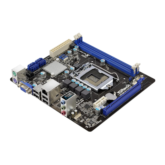
Page 9: Motherboard Layout
Top: T: USB2 RJ-45 B: USB3 HD_AUDIO1 PLED1 PCIE1 CLRCMOS1 CMOS PLED PWRBTN BATTERY H61M-XT PLUS HDLED RESET CHA_FAN1 PANEL1 AUDIO CODEC PCIE2 32Mb SPI Flash Power LED Header (PLED1) SATA2 Connector (SATA_1 (PORT 1)) System Panel Header (PANEL1) SATA2 Connector (SATA_0 (PORT 0)) -
Page 10: I/O Panel
1.4 I/O Panel PS/2 Mouse Port (Green) USB 2.0 Ports (USB23) LAN RJ-45 Port USB 2.0 Ports (USB01) Line In (Light Blue) VGA Port ** 4 Front Speaker (Lime) PS/2 Keyboard Port (Purple) Microphone (Pink) * There are two LED next to the LAN port. Please refer to the table below for the LAN port LED indications. -
Page 11: Installation
Chapter 2: Installation This is a Micro ATX form factor motherboard. Before you install the motherboard, study the coniguration of your chassis to ensure that the motherboard its into it. Make sure to unplug the power cord before installing or removing the motherboard. -
Page 12: Cpu Installation
2.3 CPU Installation For the installation of Intel 1155-Pin CPU, please follow the steps below. Load Plate Load Lever Socket Body Contact Array 1155-Pin Socket Overview Before you insert the 1155-Pin CPU into the socket, please check if the CPU surface is unclean or if there is any bent pin on the socket. Do not force to insert the CPU into the socket if above situation is found. - Page 13 Step 3. Insert the 1155-Pin CPU: Step 3-1. Hold the CPU by the edge where is marked with black line. Step 3-2. Orient the CPU with IHS (Integrated Heat Sink) up. Locate Pin1 and the two orientation key notches. orientation key notch alignment key Pin1 Pin1...
-
Page 14: Installation Of Heatsink And Cpu Fan
2.4 Installation of CPU Fan and Heatsink This motherboard is equipped with 1155-Pin socket that supports Intel 1155-Pin CPU. Please adopt the type of heatsink and cooling fan compliant with Intel 1155- Pin CPU to dissipate heat. Before you installed the heatsink, you need to spray thermal interface material between the CPU and the heatsink to improve heat dis- sipation. -
Page 15: Installation Of Memory Modules (Dimm)
2.5 Installation of Memory Modules (DIMM) This motherboard provides two 240-pin DDR3 (Double Data Rate 3) DIMM slots, and supports Dual Channel Memory Technology. For dual channel configuration, you always need to install two identical (the same brand, speed, size and chip- type) memory modules in the DDR3 DIMM slots to activate Dual Channel Memory Technology. -
Page 16: Expansion Slots (Pci Express Slots)
2.6 Expansion Slots (PCI Express Slots) There are 2 PCI Express slots on this motherboard. PCIE slots: PCIE1 (PCIE 2.0 x1 slot) is used for PCI Express x1 lane width cards. PCIE2 (PCIE 3.0 x16 slot) is used for PCI Express x16 lane width graphics cards. -
Page 17: Jumpers Setup
2.7 Jumpers Setup The illustration shows how jumpers are setup. When the jumper cap is placed on pins, the jumper is “Short”. If no jumper cap is placed on pins, the jumper is “Open”. The illustration shows a 3-pin jumper whose pin1 and pin2 are “Short”... -
Page 18: Onboard Headers And Connectors
2.8 Onboard Headers and Connectors Onboard headers and connectors are NOT jumpers. Do NOT place jumper caps over these headers and connectors. Placing jumper caps over the headers and connectors will cause permanent damage of the motherboard! Serial ATA2 Connectors These four Serial ATA2 (SATA2) connectors support (SATA_0 (PORT 0):... - Page 19 Front Panel Audio Header This is an interface for front PRESENCE# (9-pin HD_AUDIO1) panel audio cable that allows MIC_RET OUT_RET (see p.8 No. 17) convenient connection and control of audio devices. OUT2_L J_SENSE OUT2_R MIC2_R MIC2_L 1. High Deinition Audio supports Jack Sensing, but the panel wire on the chassis must support HDA to function correctly.
- Page 20 is on when the system is operating. The LED keeps blinking when the sys- tem is in S1 sleep state. The LED is off when the system is in S3/S4 sleep state or powered off (S5). HDLED (Hard Drive Activity LED): Connect to the hard drive activity LED on the chassis front panel.
- Page 21 ATX Power Connector Please connect an ATX power (24-pin ATXPWR1) supply to this connector. (see p.8 No. 8) Though this motherboard provides 24-pin ATX power connector, it can still work if you adopt a traditional 20-pin ATX power supply. To use the 20-pin ATX power supply, please plug your power supply along with Pin 1 and Pin 13.
-
Page 22: Uefi Setup Utility
Chapter 3: UEFI SETUP UTILITY 3.1 Introduction This section explains how to use the UEFI SETUP UTILITY to conigure your system. The UEFI chip on the motherboard stores the UEFI SETUP UTILITY. You may run the UEFI SETUP UTILITY when you start up the computer. Please press <F2>... -
Page 23: Navigation Keys
3.1.2 Navigation Keys Please check the following table for the function description of each navigation key. Navigation Key(s) Function Description Moves cursor left or right to select Screens Moves cursor up or down to select items + / - To change option for the selected items <Tab>... -
Page 24: Oc Tweaker Screen
3.3 OC Tweaker Screen In the OC Tweaker screen, you can set up overclocking features. CPU Coniguration CPU Ratio Use this item to change the ratio value of this motherboard. Intel SpeedStep Technology Intel SpeedStep technology is Intel’s new power saving technology. Pro- cessors can switch between multiple frequencies and voltage points to en- able power saving. - Page 25 Short Duration Power Limit Use this item to conigure short duration power limit in watts. The default value is [Auto]. Primary Plane Current Limit Use this item to conigure the maximum instantaneous current allowed for the primary plane. The default value is [Auto]. Secondary Plane Current Limit Use this item to conigure the maximum instantaneous current allowed for the secondary plane.
- Page 26 DRAM tRP Use this item to change Row Precharge Time (tRP) Auto/Manual setting. The default is [Auto]. DRAM tRAS Use this item to change RAS# Active Time (tRAS) Auto/Manual setting. The default is [Auto]. Command Rate (CR) Use this item to change Command Rate (CR) Auto/Manual setting. The default is [Auto].
- Page 27 MRC Fast Boot Use this item to enable or disable MRC Fast Boot. The default is [Enabled]. Voltage Coniguration DRAM Voltage Use this to select DRAM Voltage. The default value is [Auto].
-
Page 28: Advanced Screen
3.4 Advanced Screen In this section, you may set the conigurations for the following items: CPU Conigu- ration, North Bridge Coniguration, South Bridge Coniguration, Storage Conigura- tion, Intel(R) Rapid Start Technology, Intel(R) Smart Connect Technology, ACPI Coniguration and USB Coniguration. Setting wrong values in this section may cause the system to malfunction. -
Page 29: Cpu Coniguration
3.4.1 CPU Coniguration Intel Hyper Threading Technology To enable this feature, a computer system with an Intel processor that sup- ports Hyper-Threading technology and an operating system that includes ® ® optimization for this technology, such as Microsoft Windows XP / Vista ®... - Page 30 No-Execute Memory Protection No-Execution (NX) Memory Protection Technology is an enhancement to the IA-32 Intel Architecture. An IA-32 processor with “No Execute (NX) Memory Protection” can prevent data pages from being used by malicious software to execute codes. This option will be hidden if the current CPU does not support No-Excute Memory Protection.
-
Page 31: North Bridge Coniguration
3.4.2 North Bridge Coniguration Primary Graphics Adapter This allows you to select [Onboard] or [PCI Express] as the boot graphic adapter priority. The default value is [PCI Express]. VT-d ® ® Use this to enable or disable Intel VT-d technology (Intel Virtualization Technology for Directed I/O). -
Page 32: South Bridge Coniguration
3.4.3 South Bridge Coniguration Onboard HD Audio Select [Auto], [Enabled] or [Disabled] for the onboard HD Audio feature. If you select [Auto], the onboard HD Audio will be disabled when PCI Sound Card is plugged. Front Panel Select [Auto] or [Disabled] for the onboard HD Audio Front Panel. Onboard LAN This allows you to enable or disable the Onboard LAN feature. -
Page 33: Storage Coniguration
3.4.4 Storage Coniguration SATA Controller(s) Use this item to enable or disable the SATA Controller feature. SATA Mode Selection Use this to select SATA mode. Coniguration options: [IDE Mode], [AHCI Mode] and [Disabled]. The default value is [AHCI Mode]. AHCI (Advanced Host Controller Interface) supports NCQ and other new features that will improve SATA disk performance but IDE mode does not have these advantages. -
Page 34: Intel(R) Rapid Start Technology
3.4.5 Intel(R) Rapid Start Technology Intel(R) Rapid Start Technology Use this item to enable or disable Intel(R) Rapid Start Technology. Intel(R) Rapid Start Technology is a new zero power hibernation mode which al- lows users to resume in just 5-6 seconds. The default is [Enabled]. Entry After Select a time to enable RTC wake timer at S3 entry. -
Page 35: Intel(R) Smart Connect Technology
3.4.6 Intel(R) Smart Connect Technology Intel(R) Smart Connect Technology Use this item to enable or disable Intel(R) Smart Connect Technology. Intel(R) Smart Connect Technology keeps your e-mail and social networks, such as Twitter, Facebook, etc. updated automatically while the computer is in sleep mode. -
Page 36: Acpi Coniguration
3.4.7 ACPI Coniguration Check Ready Bit Use this item to enable or disable the feature Check Ready Bit. ACPI HPET Table Use this item to enable or disable ACPI HPET Table. The default value is [Enabled]. Please set this option to [Enabled] if you plan to use this certiication. -
Page 37: Usb Coniguration
Please disable CSM when you enable Fast Boot option. The default value is [Enabled]. 3.4.8 USB Coniguration USB 2.0 Controller Use this item to enable or disable the use of USB 2.0 controller. Legacy USB Support Use this option to select legacy support for USB devices. There are four coniguration options: [Enabled], [Auto], [Disabled] and [UEFI Setup Only]. -
Page 38: Tool
3.5 Tool OMG(Online Management Guard) Administrators are able to establish an internet curfew or restrict internet access at speciied times via OMG. You may schedule the starting and ending hours of internet access granted to other users. In order to prevent users from bypassing OMG, guest accounts without permission to modify the system time are required. - Page 39 Network Coniguration Internet Setting Use this item to set up the internet connection mode. Coniguration options: [DHCP (Auto IP)] and [PPPOE]. UEFI Download Server Use this item to select UEFI irmware download server for Internet Flash. Coniguration options: [Asia], [Europe], [USA] and [China]. Dehumidiier Function Users may prevent motherboard damages due to dampness by enabling “Dehumidiier Function”.
-
Page 40: Hardware Health Event Monitoring Screen
3.6 Hardware Health Event Monitoring Screen In this section, it allows you to monitor the status of the hardware on your system, including the parameters of the CPU temperature, motherboard temperature, CPU fan speed, chassis fan speed, and the critical voltage. CPU Fan Setting This allows you to set the CPU fan speed. -
Page 41: Boot Screen
3.7 Boot Screen In this section, it will display the available devices on your system for you to conig- ure the boot settings and the boot priority. Fast Boot Fast Boot minimizes your computer’s boot time. There are three con- iguration options: [Disabled], [Fast] and [Ultra Fast]. - Page 42 Full Screen Logo Use this item to enable or disable OEM Logo. The default value is [En- abled]. AddOn ROM Display Use this option to adjust AddOn ROM Display. If you enable the option “Full Screen Logo” but you want to see the AddOn ROM information when the system boots, please select [Enabled].
-
Page 43: Security Screen
3.8 Security Screen In this section, you may set or change the supervisor/user password for the system. For the user password, you may also clear it. Secure Boot Use this to enable or disable Secure Boot. The default value is [Disabled]. -
Page 44: Exit Screen
3.9 Exit Screen Save Changes and Exit When you select this option, the following message “Save coniguration changes and exit setup?” will pop-out. Select [Yes] to save the changes and exit the UEFI SETUP UTILITY. Discard Changes and Exit When you select this option, the following message “Discard changes and exit setup?”... -
Page 45: Software Support
Click on a speciic item then follow the installation wizard to install it. 4.2.4 Contact Information If you need to contact ASRock or want to know more about ASRock, welcome to visit ASRock’s website at http://www.asrock.com; or you may contact your dealer for further information.
Need help?
Do you have a question about the H61M-XT PLUS and is the answer not in the manual?
Questions and answers