Table of Contents
Advertisement
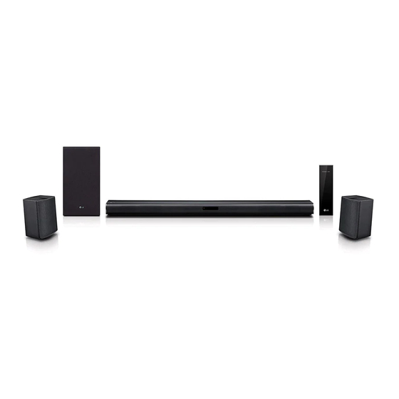
Wireless Sound Bar
SERVICE MANUAL
MODEL: SNC4R
(SNC4R, SPH4B-W)
SPJ4-S
(SPJ4-S, S65S3-S)
CAUTION
BEFORE SERVICING THE UNIT, READ THE "SAFETY PRECAUTIONS"
IN THIS MANUAL.
P/NO : AFN30054142
MARCH, 2021
"Any reproduction, duplication, distribution (including by way of email, facsimile or other
electronic means), publication, modification, copying or transmission of this Service Manual is
STRICTLY PROHIBITED unless you have obtained the prior written consent of the LG Electronics
entity from which you received this Service Manual. The material covered by this prohibition includes,
without limitation, any text, graphics or logos in this Service Manual."
Copyright © 2021 LG Electronics Inc. All rights reserved.
Only for training and service purposes.
Advertisement
Chapters
Table of Contents
Troubleshooting

Related Manuals for LG SNC4R


Summary of Contents for LG SNC4R
- Page 1 Service Manual is STRICTLY PROHIBITED unless you have obtained the prior written consent of the LG Electronics entity from which you received this Service Manual. The material covered by this prohibition includes, without limitation, any text, graphics or logos in this Service Manual.”...
- Page 2 SECTION 1 ..GENERAL SECTION 2 ..CABINET & MAIN CHASSIS SECTION 3 ..ELECTRICAL SECTION 4 ..WIRELESS SUBWOOFER PART SECTION 5 ..WIRELESS RECEIVER PART Copyright © 2021 LG Electronics Inc. All rights reserved. Only for training and service purposes.
-
Page 3: Table Of Contents
LOCATION OF CUSTOMER CONTROLS ......................1-4 WIRELESS SUBWOOFER CONNECTION ....................... 1-5 REAR SPEAKERS CONNECTION ........................1-6 HIDDEN KEY MODE ............................1-7 FIRMWARE UPDATE GUIDE ........................... 1-8 SPECIFICATIONS ............................1-11 Copyright © 2021 LG Electronics Inc. All rights reserved. Only for training and service purposes. -
Page 4: Esd Precautions
ELECTRIC SHOCK. THE EXCLAMATION POINT WITHIN AN EQUILATERAL TRIANGLE IS INTENDED TO ALERT THE SERVICE PERSONNEL TO THE PRESENCE OF IMPORTANT SAFETY INFORMATION IN SERVICE LITERATURE. Copyright © 2021 LG Electronics Inc. All rights reserved. Only for training and service purposes. -
Page 5: Location Of Customer Controls
- Connect the OPTICAL IN jack on the back of the unit to OPTICAL OUT jack on the TV. USB Port - Connect USB memory device to the USB port on the back of the unit. Copyright © 2021 LG Electronics Inc. All rights reserved. Only for training and service purposes. -
Page 6: Wireless Subwoofer Connection
PAIRING.) 2. Turn on the sound bar. - Pairing is completed. The yellow - green LED on the front of the wireless subwoofer turns on. Copyright © 2021 LG Electronics Inc. All rights reserved. Only for training and service purposes. -
Page 7: Rear Speakers Connection
+ to + and – to –. If the cables are reversed, the sound will be distorted and will lack bass. Copyright © 2021 LG Electronics Inc. All rights reserved. Only for training and service purposes. -
Page 8: Hidden Key Mode
(Volume)’ + Remote control ‘NIGHT ON’ EEPROM CLEAR (Initialize) Main unit ‘ (Volume)’ + Remote control ‘'ASC ’ VERSION CHECK Main unit ‘ (Volume)’ + Remote control ‘ (Play/Pause)’ Copyright © 2021 LG Electronics Inc. All rights reserved. Only for training and service purposes. -
Page 9: Firmware Update Guide
If wireless rear rx module is updated ※ Take care not to power off during update. ※ Do format USB memory before update (FAT32 fi le system). Copyright © 2021 LG Electronics Inc. All rights reserved. Only for training and service purposes. - Page 10 00 to 100. Step 8. Update will start automatically. VFD Model : Check VFD what module is in progress one by one. Copyright © 2021 LG Electronics Inc. All rights reserved. Only for training and service purposes.
- Page 11 * Press Play/pause button to see next option value. <SL4 VFD Display in Version Display> 3) Compare the version VFD shows and you updated. 1-10 Copyright © 2021 LG Electronics Inc. All rights reserved. Only for training and service purposes.
-
Page 12: Specifications
Approx. 100.0 mm x 140.0 mm x 100.0 mm (3.9 inch x 5.5 inch x 3.9 inch) • Designs and specifications are subject to change without prior notice. 1-11 Copyright © 2021 LG Electronics Inc. All rights reserved. Only for training and service purposes. - Page 13 1-12 Copyright © 2021 LG Electronics Inc. All rights reserved. Only for training and service purposes.
- Page 14 1. MAIN UNIT SECTION ..........................2-7 2. WIRELESS SUBWOOFER SECTION ....................2-11 3. WIRELESS RECEIVER SECTION ......................2-15 4. REAR SPEAKER SECTION ........................2-17 5. PACKING ACCESSORY SECTION ....................... 2-19 Copyright © 2021 LG Electronics Inc. All rights reserved. Only for training and service purposes.
-
Page 15: Disassembly Instructions
DISASSEMBLY INSTRUCTIONS 1. HOW TO DISASSEMBLE THE MAIN SET 1) Remove the 19 screws. Figure 1-1 2) Remove the Case Bottom Assembly. Figure 1-2 Copyright © 2021 LG Electronics Inc. All rights reserved. Only for training and service purposes. -
Page 16: How To Disassemble The Main Set
3) Remove the 2 screws, Disconnect the Harmess/FFC cables (KEY, SPK) and Remove the Main PCB Assembly. Figure 1-3 4) Remove the SPK Chamber L/R Assembly. Figure 1-4 Copyright © 2021 LG Electronics Inc. All rights reserved. Only for training and service purposes. - Page 17 HOW TO DISASSEMBLE THE MAIN SET 5) Remove the L/R Deco Assembly. Figure 1-5 6) Remove the 4 screws and Disconnect FFC cables (BT, Wireless). Wireless Figure 1-6 Copyright © 2021 LG Electronics Inc. All rights reserved. Only for training and service purposes.
- Page 18 HOW TO DISASSEMBLE THE MAIN SET 7) Remove the EMI Shield Tape. Figure 1-7 8) Remove the EMI Shield Tape of Bottom side. Figure 1-8 Copyright © 2021 LG Electronics Inc. All rights reserved. Only for training and service purposes.
- Page 19 HOW TO DISASSEMBLE THE MAIN SET 9) Disassembly fi nish. Figure 1-9 Copyright © 2021 LG Electronics Inc. All rights reserved. Only for training and service purposes.
-
Page 20: Exploded Views
EXPLODED VIEWS 1. MAIN UNIT SECTION A80R MAIN CABLE1 WIRELESS A80L CABLE4 CABLE2 CABLE3 WIRELESS Copyright © 2021 LG Electronics Inc. All rights reserved. Only for training and service purposes. - Page 21 SMMD3276-A-00-VTNF-WX BACK LIG CABLES CABLE1 EAD65485502 Harness,Single CAV-18-39 SMH200-02 to SMH200- CABLE2 EAD64105005 Cable,FFC AT10010105D01 105MM 1.00MM 10P CABLE3 EAD62131522 Cable,FFC 26P005D-H2-1F01A-T-143-64-79-0 CABLE4 EAD62131525 Cable,FFC 26P005D-H2-2F01A-T-70-15-55-0- 2-10 Copyright © 2021 LG Electronics Inc. All rights reserved. Only for training and service purposes.
-
Page 22: Wireless Subwoofer Section
TO ALERT THE SERVICE PERSONNEL TO THE PRESENCE OF IMPORTANT SAFETY INFORMATION IN SERVICE LITERATURE. A900 CN901 A47W SMPS A54W WIRELESS A45W 300W 2-11 2-12 Copyright © 2021 LG Electronics Inc. All rights reserved. Only for training and service purposes. - Page 23 MOLD ABS SPK S55A1-D MOLD Rear MCZ63611901 Duct CUTTING PAPER SPK S55A1-D OTHE MCZ63631801 Duct MOLD HIPS SPK S45A1-D MOLD INN EAD62131520 Cable,FFC 26P005D-H2-1FS-N-90-90-0-0-0-0 EAD62131520 Cable,FFC 26P005D-H2-1FS-N-90-90-0-0-0-0 2-13 2-14 Copyright © 2021 LG Electronics Inc. All rights reserved. Only for training and service purposes.
-
Page 24: Wireless Receiver Section
EQUILATERAL TRIANGLE IS INTENDED TO ALERT THE SERVICE PERSONNEL TO THE PRESENCE OF IMPORTANT SAFETY INFORMATION IN SERVICE LITERATURE. 390L A81A CN901 A81S 390R SMPS A81M WIRELESS 2-15 Copyright © 2021 LG Electronics Inc. All rights reserved. Only for training and service purposes. - Page 25 MOLD ABS HOME THEATER W2 MOLD EAD62131501 Cable,FFC AT05026080D02 80MM 0.50MM 26P MEG63059701 Holder MOLD ABS HF-380 HOME THEATER W EAD60816752 Power Cord USA95Y AT-H2P-1500/95-T-00-BK- 2-16 Copyright © 2021 LG Electronics Inc. All rights reserved. Only for training and service purposes.
-
Page 26: Rear Speaker Section
4. REAR SPEAKER SECTION A600 2-17 Copyright © 2021 LG Electronics Inc. All rights reserved. Only for training and service purposes. - Page 27 • Rear speaker parts list LOCA. NO. PART NO. DESCRIPTION SPECIFICATION REMARKS A600 TCG36668310 Speaker System Total S65S3-S SL5R.DCOLLLK 2-18 Copyright © 2021 LG Electronics Inc. All rights reserved. Only for training and service purposes.
-
Page 28: Packing Accessory Section
300 Power cord 835 Wall bracket 836 Screws (2) * Accessory 826 Filter (Ferrite Core) WIRE60 SPK cable (Rear Left) WIRE61 SPK cable (Rear Right) 2-19 Copyright © 2021 LG Electronics Inc. All rights reserved. Only for training and service purposes. - Page 29 Remote Controller Assembly MA6 SM/SL10/9/8/7/6/5/4 Soundb WIRE60 EBR72912707 PCB Assembly,Sub STANDARD AWG #24 EXTERNAL WIRE WIRE61 EBR72912708 PCB Assembly,Sub STANDARD AWG #24 EXTERNAL WIRE 2-20 Copyright © 2021 LG Electronics Inc. All rights reserved. Only for training and service purposes.
- Page 30 CIRCUIT VOLTAGE CHART ........................... 3-33 PRINTED CIRCUIT BOARD DIAGRAMS ....................... 3-35 1. MAIN P. C. BOARD DIAGRAM ......................3-35 2. KEY P. C. BOARD DIAGRAM ......................3-37 Copyright © 2021 LG Electronics Inc. All rights reserved. Only for training and service purposes.
-
Page 31: Wiring Diagram
WIRING DIAGRAM 26 PIN FFC CABLE 14 PIN FFC CABLE JK300 DC JACK 2 PIN HARNESS CN704 CN703 Copyright © 2021 LG Electronics Inc. All rights reserved. Only for training and service purposes. -
Page 32: Block Diagrams
BLOCK DIAGRAMS 1. SYSTEM BLOCK DIAGRAM Copyright © 2021 LG Electronics Inc. All rights reserved. Only for training and service purposes. -
Page 33: Power Block Diagram
RCU, STB-LED VCC33 100 mA AMP, P_CTRL Switch Front LED*4ea IC309 WIRELESS WL_3V3 100 mA Switch WL_P_CTRL_WF Module IC310 WIRELESS RBOX_3V3 100mA Switch WL_P_CTRL_RR Module IC313 Copyright © 2021 LG Electronics Inc. All rights reserved. Only for training and service purposes. -
Page 34: One Point Repair Guide
L 4 0 7 C N 4 0 2 F 3 0 1 F 3 0 0 R R 5 0 3 < MAIN board top view > Copyright © 2021 LG Electronics Inc. All rights reserved. Only for training and service purposes. - Page 35 L 4 0 7 C N 4 0 2 F 3 0 1 F 3 0 0 R R 5 0 3 < MAIN board top view > Copyright © 2021 LG Electronics Inc. All rights reserved. Only for training and service purposes.
- Page 36 D 5 0 2 R R 5 0 3 J K 5 0 1 C 5 4 4 C 5 7 0 < MAIN board top view > Copyright © 2021 LG Electronics Inc. All rights reserved. Only for training and service purposes.
- Page 37 L 4 0 7 C N 4 0 2 F 3 0 1 F 3 0 0 R R 5 0 3 < MAIN board top view > Copyright © 2021 LG Electronics Inc. All rights reserved. Only for training and service purposes.
-
Page 38: Sound
R C 5 1 6 CN504 CN504 D 5 0 3 CN506 Rear SPK C N 5 0 4 Subwoofer < MAIN board top view > Copyright © 2021 LG Electronics Inc. All rights reserved. Only for training and service purposes. - Page 39 R R 5 0 3 R C 5 1 7 R C 5 1 6 CN506 Rear SPK < MAIN board top view > 3-10 Copyright © 2021 LG Electronics Inc. All rights reserved. Only for training and service purposes.
- Page 40 R C 5 1 6 D 5 0 3 CN506 Rear SPK C N 5 0 4 Subwoofer < MAIN board top view > 3-11 Copyright © 2021 LG Electronics Inc. All rights reserved. Only for training and service purposes.
-
Page 41: Protection Error
C 5 0 3 F B 5 0 7 F B 5 0 8 C N 5 0 5 < MAIN board top view > 3-12 Copyright © 2021 LG Electronics Inc. All rights reserved. Only for training and service purposes. - Page 42 R 7 7 5 C 3 5 1 F R + C 7 3 1 R 3 0 1 < MAIN board bottom view > 3-13 Copyright © 2021 LG Electronics Inc. All rights reserved. Only for training and service purposes.
-
Page 43: Electrical Troubleshooting Guide
Check FB304 Voltage 12 VA Replace Main PCB Replace Main PCB Check FB305 Voltage 5.1 VA Check R308 Voltage 3.3 VA Replace Main PCB 3-14 Copyright © 2021 LG Electronics Inc. All rights reserved. Only for training and service purposes. - Page 44 Check FB304 Voltage 12 VA Replace Main PCB Replace Main PCB Check FB305 Voltage 5.1 VA Check R314 Voltage 1.3 VA Replace Main PCB 3-15 Copyright © 2021 LG Electronics Inc. All rights reserved. Only for training and service purposes.
- Page 45 Check F301 Voltage 25 VA Check FB304 Voltage 12 VA Check IC302 Replace Main PCB Check R774 Check Q301 2pin Voltage 12 V Voltage 12 V 3-16 Copyright © 2021 LG Electronics Inc. All rights reserved. Only for training and service purposes.
- Page 46 Check FB304 Voltage 12 VA Replace Main PCB Replace Main PCB Check FB305 Voltage 5.1 VA Check FB306 Voltage 5 V Replace Main PCB 3-17 Copyright © 2021 LG Electronics Inc. All rights reserved. Only for training and service purposes.
- Page 47 Check FB304 Voltage 12 VA Replace Main PCB Replace Main PCB Check FB305 Voltage 5.1 VA Check R311 Voltage 3.3 V Replace Main PCB 3-18 Copyright © 2021 LG Electronics Inc. All rights reserved. Only for training and service purposes.
- Page 48 Check FB304 Voltage 12 VA Replace Main PCB Replace Main PCB Check FB305 Voltage 5.1 V A Check FB311 Voltage 3.3 V Replace Main PCB 3-19 Copyright © 2021 LG Electronics Inc. All rights reserved. Only for training and service purposes.
- Page 49 Replace Main PCB Check FB305 Voltage 5.1 VA Check R308 Voltage 3.3 VA Replace Main PCB Check FB313 Voltage 3.3 V Replace Main PCB 3-20 Copyright © 2021 LG Electronics Inc. All rights reserved. Only for training and service purposes.
- Page 50 Replace Main PCB Check FB305 Voltage 5.1 VA Check R308 Voltage 3.3 VA Replace Main PCB Check FB314 Voltage 3.3 V Replace Main PCB 3-21 Copyright © 2021 LG Electronics Inc. All rights reserved. Only for training and service purposes.
- Page 51 Replace Main PCB Check FB305 Voltage 5.1 VA Check R308 Voltage 3.3 VA Replace Main PCB Check FB316 Voltage 3.3 V Replace Main PCB 3-22 Copyright © 2021 LG Electronics Inc. All rights reserved. Only for training and service purposes.
-
Page 52: Key Part
Check the connecting cables Voltage 3.3 V Check R520 Pull-up Resistor Replace the Key PCB Check SWA01, SWA02, Check RA01, RA04, RA05, RA06 SWA03, SWA04 3-23 Copyright © 2021 LG Electronics Inc. All rights reserved. Only for training and service purposes. -
Page 53: Usb Function
Check FB306 Voltage 5.1 V Check IC306 Check JK501 1pin Voltage 5.1 V Replace Main PCB Check Reading OK Check JK501 pin2(D-), pin3(D+) IC501 pin35, pin36 3-24 Copyright © 2021 LG Electronics Inc. All rights reserved. Only for training and service purposes. -
Page 54: Optical Function
Replace Main PCB Check JK502 Check R528 Check R549 3.3VA Voltage Refer to Power Part Troubleshooting Check IC501 pin65 Check C511 Input waveform Replace Main PCB 3-25 Copyright © 2021 LG Electronics Inc. All rights reserved. Only for training and service purposes. -
Page 55: Waveforms Of Major Check Point
SF_CS 4 FLOAT R557 IN/OUT 0 OHM(1) HOLD# DGND 1 IN/OUT FLOAT SCLK C518 C517 10pF 10pF R559 For DSP(2MB) 0 OHM(1) DGND DGND 3-26 Copyright © 2021 LG Electronics Inc. All rights reserved. Only for training and service purposes. -
Page 56: Tact Key
SWA04 C564 CA00 VD33ADAC 100nF R521 4.7K DGND C526 10uF POWER WIFI VOL+ VOL- FUNC. R567 0 NC DGND R588 PWM_VREF VD33ADAC IC501 VS33ADAC 3-27 Copyright © 2021 LG Electronics Inc. All rights reserved. Only for training and service purposes. -
Page 57: Usb
FIG 4-2. USB D+ FIG 4-3. USB D- USB_5V JK501 USB5V USB_N USB_P USB_GND DGND C545 C544 C546 220uF 100nF 10uF D502 D503 DGND 3-28 Copyright © 2021 LG Electronics Inc. All rights reserved. Only for training and service purposes. -
Page 58: Remote Control
“ Low” Timing 4.4 ms 3.6 ms ~ 5.04 ms “ High” Timing 4.48 ms 4.08 ms ~ 5.04 ms FIG 5-3. High Timing 3-29 Copyright © 2021 LG Electronics Inc. All rights reserved. Only for training and service purposes. -
Page 59: Optical
OPT_IN R527 3.9K OPT_DET 1.3VA R526 VD33 C555 R566 SR[24] WL_MSG_RDY_RR R514 SR[23] WL_INT_RR R550 SR[22] AMP_PDN IC501 R551 SR[17] AMP_FAULT R516 SR[16] TUNER_P_CTRL 3-30 Copyright © 2021 LG Electronics Inc. All rights reserved. Only for training and service purposes. - Page 60 TGND C439 10uF R4C3 TUNER_RST R4N4 TGND TGND TUNER_CE R4N5 TUNER_CLK R4N8 TGND TUNER_DAT DGND C4A4 C4A5 C4A6 33pF 33pF 33pF DGND DGND DGND 3-31 Copyright © 2021 LG Electronics Inc. All rights reserved. Only for training and service purposes.
- Page 61 3-32 Copyright © 2021 LG Electronics Inc. All rights reserved. Only for training and service purposes.
-
Page 62: Circuit Voltage Chart
VDD: 11.9 V DVDD: 8 DVDD: -0.3 V ~ 4.2 V DVDD: 3.32 V AVDD: 13 AVDD: -0.3 V ~ 8.5 V AVDD: 7.76 V 3-33 3-34 Copyright © 2021 LG Electronics Inc. All rights reserved. Only for training and service purposes. -
Page 63: Printed Circuit Board Diagrams
C 5 1 4 U S B _ N G S 3 0 1 U S B _ P U S B _ G N D 3-35 3-36 Copyright © 2021 LG Electronics Inc. All rights reserved. Only for training and service purposes. -
Page 64: Key P. C. Board Diagram
F R 4 - 2 L 1 . 2 T 2 0 1 8 . 1 2 . 0 7 P C B S I Z E : 4 0 . 6 X 3 0 3-37 3-38 Copyright © 2021 LG Electronics Inc. All rights reserved. Only for training and service purposes. - Page 65 3-39 3-40 Copyright © 2021 LG Electronics Inc. All rights reserved. Only for training and service purposes.
- Page 66 PRINTED CIRCUIT BOARD DIAGRAMS ....................... 4-15 1. WOOFER SMPS P. C. BOARD ......................4-15 2. WOOFER AMP P. C. BOARD ......................4-17 3. WOOFER KEY P. C. BOARD ....................... 4-17 Copyright © 2021 LG Electronics Inc. All rights reserved. Only for training and service purposes.
-
Page 67: One Point Repair Guide
WIC607 Nearby WC686 Nearby WC686 < Woofer AMP board top view > PVDD PVDD at WCA601 at WCA601 < Woofer AMP board bottom view > Copyright © 2021 LG Electronics Inc. All rights reserved. Only for training and service purposes. -
Page 68: Power On Error
PVDD PVDD at pin7 of WIC607 at pin7 of WIC607 3.7 VA 3.7 VA at WL606 at WL606 < Woofer AMP board top view > Copyright © 2021 LG Electronics Inc. All rights reserved. Only for training and service purposes. - Page 69 8 of WIC603 3.3V_PWM 3.3V_PWM 3.3V_PWM 3.3V_PWM at WL615 at WL615 at pin5 of WIC605 at pin5 of WIC605 < Woofer AMP board top view > Copyright © 2021 LG Electronics Inc. All rights reserved. Only for training and service purposes.
-
Page 70: Wireless Connection
Wireless module Wireless module Connection check Connection check < Woofer AMP board top view > Pairing key Pairing key < Woofer KEY board top view > Copyright © 2021 LG Electronics Inc. All rights reserved. Only for training and service purposes. -
Page 71: Waveforms Of Major Check Point
WAVEFORMS OF MAJOR CHECK POINT 1. VOLTAGE FIG 1-1. WIC607 3.7 VA FIG 1-2. PWM 3.3 V FIG 1-3. Wireless 3.3 VA Copyright © 2021 LG Electronics Inc. All rights reserved. Only for training and service purposes. -
Page 72: Amp Voltage
2. AMP VOLTAGE PVDD: 34.5 V FIG 2-1. Woofer PVDD FIG 2-2. Woofer 12 V Copyright © 2021 LG Electronics Inc. All rights reserved. Only for training and service purposes. -
Page 73: Pwm
3. PWM FIG 3-1. Woofer PWM SW+ SIgnal FIG 3-2. Woofer PWM SW- SIgnal Copyright © 2021 LG Electronics Inc. All rights reserved. Only for training and service purposes. -
Page 74: Led
4. LED FIG 4-1. Pairing Off Status Red LED FIG 4-2. Pairing On Status Yellow LED Copyright © 2021 LG Electronics Inc. All rights reserved. Only for training and service purposes. - Page 75 4-10 Copyright © 2021 LG Electronics Inc. All rights reserved. Only for training and service purposes.
-
Page 76: Wiring Diagram
FFC SMD 24 Pin straight Harness 12Pin Connector Harness Cable 12Pin Pairing Key 2Pin Harness DIP 2pin Cable 2Pin SMPS PCB AMP PCB LED CNT Pairing Key 4-11 4-12 Copyright © 2021 LG Electronics Inc. All rights reserved. Only for training and service purposes. -
Page 77: Block Diagram
BLOCK DIAGRAM PVDD PWM_SW+ WOOFER PWM_SW- WOOFER PWM 3.3 3.7 V PVDD DC-DC 12 V Wireless 3.3 Flash PVDD DC-DC 4-13 4-14 Copyright © 2021 LG Electronics Inc. All rights reserved. Only for training and service purposes. -
Page 78: Printed Circuit Board Diagrams
1. WOOFER SMPS P. C. BOARD (TOP VIEW) (BOTTOM VIEW) NOTE) Warning Parts that are critical with respect to risk of fire or electrical shock. 4-15 4-16 Copyright © 2021 LG Electronics Inc. All rights reserved. Only for training and service purposes. -
Page 79: Woofer Amp P. C. Board
2. WOOFER AMP P. C. BOARD (TOP VIEW) (BOTTOM VIEW) 3. WOOFER KEY P. C. BOARD (TOP VIEW) (BOTTOM VIEW) 4-17 4-18 Copyright © 2021 LG Electronics Inc. All rights reserved. Only for training and service purposes. - Page 80 WAVEFORMS ..............................5-7 PRINTED CIRCUIT BOARD DIAGRAMS ......................5-9 1. WIRELESS RECEIVER SMPS P. C. BOARD ..................5-9 2. WIRELESS RECEIVER AMP P. C. BOARD ..................5-11 Copyright © 2021 LG Electronics Inc. All rights reserved. Only for training and service purposes.
-
Page 81: Wiring Diagram
WIRING DIAGRAM Copyright © 2021 LG Electronics Inc. All rights reserved. Only for training and service purposes. -
Page 82: Block Diagram
BLOCK DIAGRAM Wireless LED (RED, GREEN) Wireless AMP_PDN AMP_SD PAIRING R R eset KEY RL+,-/RR+,- PWM IC Copyright © 2021 LG Electronics Inc. All rights reserved. Only for training and service purposes. -
Page 83: One Point Repair Guide
Check 3.3 V. Replace AMP board. 2-3. Service hint (Any picture / Remark) RIC308 RIC308 RIC308 RIC307 RIC307 RIC307 < AMP board top view > Copyright © 2021 LG Electronics Inc. All rights reserved. Only for training and service purposes. - Page 84 Check Module or connection. Replace AMP board. 3-3. Service hint (Any picture / Remark) RIC308 RIC308 RIC308 RIC307 RIC307 RIC307 < AMP board top view > Copyright © 2021 LG Electronics Inc. All rights reserved. Only for training and service purposes.
-
Page 85: Electrical Troubleshooting Guide
(RCN301 pin9, 10) no output. AMP 12 V (RIC308 pin4) Check RIC308. no output. 3.3 V (RIC307 pin3) Check RIC307. no output. Check Module or Connection. Copyright © 2021 LG Electronics Inc. All rights reserved. Only for training and service purposes. -
Page 86: Waveforms
WAVEFORMS 1. AUDIO PART (I2S) RCN303 pin1 : I2S LRCK RCN303 pin3 : I2S BCK RCN303 pin20 : I2S Audio Data Copyright © 2021 LG Electronics Inc. All rights reserved. Only for training and service purposes. - Page 87 Copyright © 2021 LG Electronics Inc. All rights reserved. Only for training and service purposes.
-
Page 88: Printed Circuit Board Diagrams
1. WIRELESS RECEIVER SMPS P. C. BOARD (TOP VIEW) (BOTTOM VIEW) NOTE) Warning Parts that are critical with respect to risk of fire or electrical shock. 5-10 Copyright © 2021 LG Electronics Inc. All rights reserved. Only for training and service purposes. -
Page 89: Wireless Receiver Amp P. C. Board
2. WIRELESS RECEIVER AMP P. C. BOARD (TOP VIEW) (BOTTOM VIEW) 5-11 5-12 Copyright © 2021 LG Electronics Inc. All rights reserved. Only for training and service purposes.
Need help?
Do you have a question about the SNC4R and is the answer not in the manual?
Questions and answers
How do I turn it on if I lost the remote