Table of Contents
Advertisement
CONFIDENTIAL
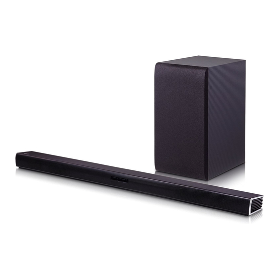
Wireless Sound Bar
SERVICE MANUAL
MODEL: SL4Y
(SL4Y, SPH4B-W)
CAUTION
BEFORE SERVICING THE UNIT, READ THE "SAFETY PRECAUTIONS"
IN THIS MANUAL.
P/NO : AFN79154806
MAY, 2019
"Any reproduction, duplication, distribution (including by way of email, facsimile or other
electronic means), publication, modification, copying or transmission of this Service Manual is
STRICTLY PROHIBITED unless you have obtained the prior written consent of the LG Electronics
entity from which you received this Service Manual. The material covered by this prohibition includes,
without limitation, any text, graphics or logos in this Service Manual."
Copyright © 2019 LG Electronics Inc. All rights reserved.
Only for training and service purposes.
Advertisement
Chapters
Table of Contents

Related Manuals for LG SL4Y


Summary of Contents for LG SL4Y
- Page 1 Service Manual is STRICTLY PROHIBITED unless you have obtained the prior written consent of the LG Electronics entity from which you received this Service Manual. The material covered by this prohibition includes, without limitation, any text, graphics or logos in this Service Manual.”...
- Page 2 CONTENTS SECTION 1 ..GENERAL SECTION 2 ..CABINET & MAIN CHASSIS SECTION 3 ..ELECTRICAL SECTION 4 ..WIRELESS SUBWOOFER PART Copyright © 2019 LG Electronics Inc. All rights reserved. Only for training and service purposes.
-
Page 3: Table Of Contents
WIRELESS SUBWOOFER CONNECTION ....................... 1-5 REAR SPEAKERS CONNECTION (SOLD SEPARATELY) ................1-6 HIDDEN KEY MODE ............................1-7 FIRMWARE UPDATE GUIDE ........................... 1-8 SPECIFICATIONS ............................1-11 Copyright © 2019 LG Electronics Inc. All rights reserved. Only for training and service purposes. -
Page 4: Esd Precautions
ELECTRIC SHOCK. THE EXCLAMATION POINT WITHIN AN EQUILATERAL TRIANGLE IS INTENDED TO ALERT THE SERVICE PERSONNEL TO THE PRESENCE OF IMPORTANT SAFETY INFORMATION IN SERVICE LITERATURE. Copyright © 2019 LG Electronics Inc. All rights reserved. Only for training and service purposes. -
Page 5: Location Of Customer Controls
- Connect the OPTICAL IN jack on the back of the unit to OPTICAL OUT jack on the TV. USB Port - Connect USB memory device to the USB port on the back of the unit. Copyright © 2019 LG Electronics Inc. All rights reserved. Only for training and service purposes. -
Page 6: Wireless Subwoofer Connection
PAIRING.) 2. Turn on the sound bar. - Pairing is completed. The yellow - green LED on the front of the wireless subwoofer turns on. Copyright © 2019 LG Electronics Inc. All rights reserved. Only for training and service purposes. -
Page 7: Rear Speakers Connection (Sold Separately)
+ to + and – to –. If the cables are reversed, the sound will be distorted and will lack bass. Copyright © 2019 LG Electronics Inc. All rights reserved. Only for training and service purposes. -
Page 8: Hidden Key Mode
EEPROM EDIT Main unit ‘ (Volume)’ + Remote control ‘'ASC ’ EEPROM CLEAR (Initialize) Main unit ‘ (Volume)’ + Remote control ‘ (Play/Pause)’ VERSION CHECK Copyright © 2019 LG Electronics Inc. All rights reserved. Only for training and service purposes. -
Page 9: Firmware Update Guide
FIRMWARE UPDATE GUIDE 1. Preparation 1) SL4Y Series Units : Main Unit, Wireless Subwoofer Unit, Rear Speaker Unit(optional). 2) SL4Y RCU. 3) USB Memory. 4) Android Device with “Music Flow Bluetooth” App for FOTA update, “Version Check APP” for Version Check. - Page 10 Step 6. Press Function key to change function to USB. Verify whether USB function is or not by VFD. Step 7.Attach USB which has update binaries to the USB slot back of SL4Y main unit. Update module VFD display...
- Page 11 USB Update Step 9. SL4Y main unit will be off automatically after update f nish. Step 10. Power on SL4Y main unit again. Step 11. Check the current versions to verify whether the update was successfully completed or not. 1) Press “Version Check” hidden key •...
-
Page 12: Specifications
Dimensions (W x H x D) Approx. 100.0 mm x 140.0 mm x 100.0 mm • Designs and specifications are subject to change without prior notice. Copyright © 2019 LG Electronics Inc. All rights reserved. 1-11 Only for training and service purposes. - Page 13 Copyright © 2019 LG Electronics Inc. All rights reserved. 1-12 Only for training and service purposes.
- Page 14 1. HOW TO DISASSEMBLE THE MAIN SET ....................2-2 EXPLODED VIEWS ............................2-7 1. MAIN UNIT SECTION ..........................2-7 2. WIRELESS SUBWOOFER SECTION ....................2-11 3. PACKING ACCESSORY SECTION ....................... 2-15 Copyright © 2019 LG Electronics Inc. All rights reserved. Only for training and service purposes.
-
Page 15: Disassembly Instructions
DISASSEMBLY INSTRUCTIONS 1. HOW TO DISASSEMBLE THE MAIN SET 1) Remove the 19 screws. Figure 1-1 2) Remove the Case Bottom Assembly. Figure 1-2 Copyright © 2019 LG Electronics Inc. All rights reserved. Only for training and service purposes. -
Page 16: How To Disassemble The Main Set
3) Remove the 2 screws, Disconnect the Harmess/FFC cables (KEY, SPK) and Remove the Main PCB Assembly. Figure 1-3 4) Remove the SPK Chamber L/R Assembly. Figure 1-4 Copyright © 2019 LG Electronics Inc. All rights reserved. Only for training and service purposes. - Page 17 HOW TO DISASSEMBLE THE MAIN SET 5) Remove the L/R Deco Assembly. Figure 1-5 6) Remove the 4 screws and Disconnect FFC cables (BT, Wireless). Wireless Figure 1-6 Copyright © 2019 LG Electronics Inc. All rights reserved. Only for training and service purposes.
- Page 18 HOW TO DISASSEMBLE THE MAIN SET 7) Remove the EMI Shield Tape. Figure 1-7 8) Remove the EMI Shield Tape of Bottom side. Figure 1-8 Copyright © 2019 LG Electronics Inc. All rights reserved. Only for training and service purposes.
- Page 19 HOW TO DISASSEMBLE THE MAIN SET 9) Disassembly f nish. Figure 1-9 Copyright © 2019 LG Electronics Inc. All rights reserved. Only for training and service purposes.
-
Page 20: Exploded Views
EXPLODED VIEWS 1. MAIN UNIT SECTION CABLE5 A80R MAIN CABLE6 CABLE1 A80L WIRELESS CABLE4 CABLE2 CABLE3 WIRELESS Copyright © 2019 LG Electronics Inc. All rights reserved. Only for training and service purposes. -
Page 21: Wireless Subwoofer Section
TO ALERT THE SERVICE PERSONNEL TO THE PRESENCE OF IMPORTANT SAFETY INFORMATION IN SERVICE LITERATURE. A900 CN901 A47W SMPS A49W A54W WIRELESS A45W 300W 2-11 2-12 Copyright © 2019 LG Electronics Inc. All rights reserved. Only for training and service purposes. -
Page 22: Packing Accessory Section
Optional Part 806 Optical cable 900 Remote control 833 AC adapter 300 Power cord 835 Wall bracket 837 Holder, foot 836 Screws (2) Copyright © 2019 LG Electronics Inc. All rights reserved. 2-15 Only for training and service purposes. - Page 23 CIRCUIT VOLTAGE CHART ........................... 3-33 PRINTED CIRCUIT BOARD DIAGRAMS ....................... 3-35 1. MAIN P. C. BOARD DIAGRAM ......................3-35 2. KEY P. C. BOARD DIAGRAM ......................3-37 Copyright © 2019 LG Electronics Inc. All rights reserved. Only for training and service purposes.
-
Page 24: Wiring Diagram
WIRING DIAGRAM 26 PIN FFC CABLE 14 PIN FFC CABLE JK300 DC JACK 2 PIN HARNESS CN704 CN703 Copyright © 2019 LG Electronics Inc. All rights reserved. Only for training and service purposes. -
Page 25: Block Diagrams
BLOCK DIAGRAMS 1. SYSTEM BLOCK DIAGRAM Copyright © 2019 LG Electronics Inc. All rights reserved. Only for training and service purposes. -
Page 26: Power Block Diagram
RCU, STB-LED VCC33 100 mA AMP, P_CTRL Switch Front LED*4ea IC309 WIRELESS WL_3V3 100 mA Switch WL_P_CTRL_WF Module IC310 WIRELESS RBOX_3V3 100mA Switch WL_P_CTRL_RR Module IC313 Copyright © 2019 LG Electronics Inc. All rights reserved. Only for training and service purposes. -
Page 27: One Point Repair Guide
L 4 0 7 C N 4 0 2 F 3 0 1 F 3 0 0 R R 5 0 3 < MAIN board top view > Copyright © 2019 LG Electronics Inc. All rights reserved. Only for training and service purposes. - Page 28 L 4 0 7 C N 4 0 2 F 3 0 1 F 3 0 0 R R 5 0 3 < MAIN board top view > Copyright © 2019 LG Electronics Inc. All rights reserved. Only for training and service purposes.
- Page 29 D 5 0 2 R R 5 0 3 J K 5 0 1 C 5 4 4 C 5 7 0 < MAIN board top view > Copyright © 2019 LG Electronics Inc. All rights reserved. Only for training and service purposes.
- Page 30 L 4 0 7 C N 4 0 2 F 3 0 1 F 3 0 0 R R 5 0 3 < MAIN board top view > Copyright © 2019 LG Electronics Inc. All rights reserved. Only for training and service purposes.
-
Page 31: Sound
R C 5 1 6 CN504 CN504 D 5 0 3 CN506 Rear SPK C N 5 0 4 Subwoofer < MAIN board top view > Copyright © 2019 LG Electronics Inc. All rights reserved. Only for training and service purposes. - Page 32 R R 5 0 3 R C 5 1 7 R C 5 1 6 CN506 Rear SPK < MAIN board top view > Copyright © 2019 LG Electronics Inc. All rights reserved. 3-10 Only for training and service purposes.
- Page 33 R C 5 1 6 D 5 0 3 CN506 Rear SPK C N 5 0 4 Subwoofer < MAIN board top view > Copyright © 2019 LG Electronics Inc. All rights reserved. 3-11 Only for training and service purposes.
-
Page 34: Protection Error
C 5 0 3 F B 5 0 7 F B 5 0 8 C N 5 0 5 < MAIN board top view > Copyright © 2019 LG Electronics Inc. All rights reserved. 3-12 Only for training and service purposes. - Page 35 R 7 7 5 C 3 5 1 F R + C 7 3 1 R 3 0 1 < MAIN board bottom view > Copyright © 2019 LG Electronics Inc. All rights reserved. 3-13 Only for training and service purposes.
-
Page 36: Electrical Troubleshooting Guide
Check FB304 Voltage 12 VA Replace Main PCB Replace Main PCB Check FB305 Voltage 5.1 VA Check R308 Voltage 3.3 VA Replace Main PCB Copyright © 2019 LG Electronics Inc. All rights reserved. 3-14 Only for training and service purposes. - Page 37 Check FB304 Voltage 12 VA Replace Main PCB Replace Main PCB Check FB305 Voltage 5.1 VA Check R314 Voltage 1.3 VA Replace Main PCB Copyright © 2019 LG Electronics Inc. All rights reserved. 3-15 Only for training and service purposes.
- Page 38 Check F301 Voltage 25 VA Check FB304 Voltage 12 VA Check IC302 Replace Main PCB Check R774 Check Q301 2pin Voltage 12 V Voltage 12 V Copyright © 2019 LG Electronics Inc. All rights reserved. 3-16 Only for training and service purposes.
- Page 39 Check FB304 Voltage 12 VA Replace Main PCB Replace Main PCB Check FB305 Voltage 5.1 VA Check FB306 Voltage 5 V Replace Main PCB Copyright © 2019 LG Electronics Inc. All rights reserved. 3-17 Only for training and service purposes.
- Page 40 Check FB304 Voltage 12 VA Replace Main PCB Replace Main PCB Check FB305 Voltage 5.1 VA Check R311 Voltage 3.3 V Replace Main PCB Copyright © 2019 LG Electronics Inc. All rights reserved. 3-18 Only for training and service purposes.
- Page 41 Check FB304 Voltage 12 VA Replace Main PCB Replace Main PCB Check FB305 Voltage 5.1 V A Check FB311 Voltage 3.3 V Replace Main PCB Copyright © 2019 LG Electronics Inc. All rights reserved. 3-19 Only for training and service purposes.
- Page 42 Replace Main PCB Check FB305 Voltage 5.1 VA Check R308 Voltage 3.3 VA Replace Main PCB Check FB313 Voltage 3.3 V Replace Main PCB Copyright © 2019 LG Electronics Inc. All rights reserved. 3-20 Only for training and service purposes.
- Page 43 Replace Main PCB Check FB305 Voltage 5.1 VA Check R308 Voltage 3.3 VA Replace Main PCB Check FB314 Voltage 3.3 V Replace Main PCB Copyright © 2019 LG Electronics Inc. All rights reserved. 3-21 Only for training and service purposes.
- Page 44 Replace Main PCB Check FB305 Voltage 5.1 VA Check R308 Voltage 3.3 VA Replace Main PCB Check FB316 Voltage 3.3 V Replace Main PCB Copyright © 2019 LG Electronics Inc. All rights reserved. 3-22 Only for training and service purposes.
-
Page 45: Key Part
Check the connecting cables Voltage 3.3 V Check R520 Pull-up Resistor Replace the Key PCB Check SWA01, SWA02, Check RA01, RA04, RA05, RA06 SWA03, SWA04 Copyright © 2019 LG Electronics Inc. All rights reserved. 3-23 Only for training and service purposes. -
Page 46: Usb Function
Check FB306 Voltage 5.1 V Check IC306 Check JK501 1pin Voltage 5.1 V Replace Main PCB Check Reading OK Check JK501 pin2(D-), pin3(D+) IC501 pin35, pin36 Copyright © 2019 LG Electronics Inc. All rights reserved. 3-24 Only for training and service purposes. -
Page 47: Optical Function
Replace Main PCB Check JK502 Check R528 Check R549 3.3VA Voltage Refer to Power Part Troubleshooting Check IC501 pin65 Check C511 Input waveform Replace Main PCB Copyright © 2019 LG Electronics Inc. All rights reserved. 3-25 Only for training and service purposes. -
Page 48: Waveforms Of Major Check Point
SF_CS 4 FLOAT R557 IN/OUT 0 OHM(1) HOLD# DGND 1 IN/OUT FLOAT SCLK C518 C517 10pF 10pF R559 For DSP(2MB) 0 OHM(1) DGND DGND Copyright © 2019 LG Electronics Inc. All rights reserved. 3-26 Only for training and service purposes. -
Page 49: Tact Key
SWA04 C564 CA00 VD33ADAC 100nF R521 4.7K DGND C526 10uF POWER WIFI VOL+ VOL- FUNC. R567 0 NC DGND R588 PWM_VREF VD33ADAC IC501 VS33ADAC Copyright © 2019 LG Electronics Inc. All rights reserved. 3-27 Only for training and service purposes. -
Page 50: Usb
FIG 4-2. USB D+ FIG 4-3. USB D- USB_5V JK501 USB5V USB_N USB_P USB_GND DGND C545 C544 C546 220uF 100nF 10uF D502 D503 DGND Copyright © 2019 LG Electronics Inc. All rights reserved. 3-28 Only for training and service purposes. -
Page 51: Remote Control
“ Low” Timing 4.4 ms 3.6 ms ~ 5.04 ms “ High” Timing 4.48 ms 4.08 ms ~ 5.04 ms FIG 5-3. High Timing Copyright © 2019 LG Electronics Inc. All rights reserved. 3-29 Only for training and service purposes. -
Page 52: Optical
OPT_IN R527 3.9K OPT_DET 1.3VA R526 VD33 C555 R566 SR[24] WL_MSG_RDY_RR R514 SR[23] WL_INT_RR R550 IC501 SR[22] AMP_PDN R551 SR[17] AMP_FAULT R516 SR[16] TUNER_P_CTRL Copyright © 2019 LG Electronics Inc. All rights reserved. 3-30 Only for training and service purposes. - Page 53 TGND C439 10uF R4C3 TUNER_RST R4N4 TGND TGND TUNER_CE R4N5 TUNER_CLK R4N8 TGND TUNER_DAT DGND C4A4 C4A5 C4A6 33pF 33pF 33pF DGND DGND DGND Copyright © 2019 LG Electronics Inc. All rights reserved. 3-31 Only for training and service purposes.
- Page 54 Copyright © 2019 LG Electronics Inc. All rights reserved. 3-32 Only for training and service purposes.
-
Page 55: Circuit Voltage Chart
VDD: 11.9 V DVDD: 8 DVDD: -0.3 V ~ 4.2 V DVDD: 3.32 V AVDD: 13 AVDD: -0.3 V ~ 8.5 V AVDD: 7.76 V 3-33 3-34 Copyright © 2019 LG Electronics Inc. All rights reserved. Only for training and service purposes. -
Page 56: Printed Circuit Board Diagrams
C 5 1 4 U S B _ N G S 3 0 1 U S B _ P U S B _ G N D 3-35 3-36 Copyright © 2019 LG Electronics Inc. All rights reserved. Only for training and service purposes. -
Page 57: Key P. C. Board Diagram
F R 4 - 2 L 1 . 2 T 2 0 1 8 . 1 2 . 0 7 P C B S I Z E : 4 0 . 6 X 3 0 3-37 3-38 Copyright © 2019 LG Electronics Inc. All rights reserved. Only for training and service purposes. - Page 58 3-39 3-40 Copyright © 2019 LG Electronics Inc. All rights reserved. Only for training and service purposes.
- Page 59 PRINTED CIRCUIT BOARD DIAGRAMS ....................... 4-15 1. WOOFER SMPS P. C. BOARD ......................4-15 2. WOOFER AMP P. C. BOARD ......................4-17 3. WOOFER KEY P. C. BOARD ....................... 4-17 Copyright © 2019 LG Electronics Inc. All rights reserved. Only for training and service purposes.
-
Page 60: One Point Repair Guide
WIC607 Nearby WC686 Nearby WC686 < Woofer AMP board top view > PVDD PVDD at WCA601 at WCA601 < Woofer AMP board bottom view > Copyright © 2019 LG Electronics Inc. All rights reserved. Only for training and service purposes. -
Page 61: Power On Error
PVDD PVDD at pin7 of WIC607 at pin7 of WIC607 3.7 VA 3.7 VA at WL606 at WL606 < Woofer AMP board top view > Copyright © 2019 LG Electronics Inc. All rights reserved. Only for training and service purposes. - Page 62 8 of WIC603 3.3V_PWM 3.3V_PWM 3.3V_PWM 3.3V_PWM at WL615 at WL615 at pin5 of WIC605 at pin5 of WIC605 < Woofer AMP board top view > Copyright © 2019 LG Electronics Inc. All rights reserved. Only for training and service purposes.
-
Page 63: Wireless Connection
Wireless module Wireless module Connection check Connection check < Woofer AMP board top view > Pairing key Pairing key < Woofer KEY board top view > Copyright © 2019 LG Electronics Inc. All rights reserved. Only for training and service purposes. -
Page 64: Waveforms Of Major Check Point
WAVEFORMS OF MAJOR CHECK POINT 1. VOLTAGE FIG 1-1. WIC607 3.7 VA FIG 1-2. PWM 3.3 V FIG 1-3. Wireless 3.3 VA Copyright © 2019 LG Electronics Inc. All rights reserved. Only for training and service purposes. -
Page 65: Amp Voltage
2. AMP VOLTAGE PVDD: 34.5 V FIG 2-1. Woofer PVDD FIG 2-2. Woofer 12 V Copyright © 2019 LG Electronics Inc. All rights reserved. Only for training and service purposes. -
Page 66: Pwm
3. PWM FIG 3-1. Woofer PWM SW+ SIgnal FIG 3-2. Woofer PWM SW- SIgnal Copyright © 2019 LG Electronics Inc. All rights reserved. Only for training and service purposes. -
Page 67: Led
4. LED FIG 4-1. Pairing Off Status Red LED FIG 4-2. Pairing On Status Yellow LED Copyright © 2019 LG Electronics Inc. All rights reserved. Only for training and service purposes. - Page 68 Copyright © 2019 LG Electronics Inc. All rights reserved. 4-10 Only for training and service purposes.
-
Page 69: Wiring Diagram
FFC SMD 24 Pin straight Harness 12Pin Connector Harness Cable 12Pin Pairing Key 2Pin Harness DIP 2pin SMPS PCB AMP PCB Cable 2Pin LED CNT Pairing Key 4-11 4-12 Copyright © 2019 LG Electronics Inc. All rights reserved. Only for training and service purposes. -
Page 70: Block Diagram
BLOCK DIAGRAM PVDD PWM_SW+ WOOFER WOOFER PWM_SW- PWM 3.3 3.7 V PVDD DC-DC 12 V Wireless 3.3 Flash PVDD DC-DC 4-13 4-14 Copyright © 2019 LG Electronics Inc. All rights reserved. Only for training and service purposes. -
Page 71: Printed Circuit Board Diagrams
1. WOOFER SMPS P. C. BOARD (TOP VIEW) (BOTTOM VIEW) NOTE) Warning Parts that are critical with respect to risk of fire or electrical shock. 4-15 4-16 Copyright © 2019 LG Electronics Inc. All rights reserved. Only for training and service purposes. -
Page 72: Woofer Amp P. C. Board
2. WOOFER AMP P. C. BOARD (TOP VIEW) (BOTTOM VIEW) 3. WOOFER KEY P. C. BOARD (TOP VIEW) (BOTTOM VIEW) 4-17 4-18 Copyright © 2019 LG Electronics Inc. All rights reserved. Only for training and service purposes.
Need help?
Do you have a question about the SL4Y and is the answer not in the manual?
Questions and answers