Table of Contents
Advertisement
Quick Links
Advertisement
Table of Contents

Related Manuals for uniview technologies CI111UNV37


Summary of Contents for uniview technologies CI111UNV37
- Page 1 Network Bullet Cameras Quick Guide Manual Version: V1.01...
- Page 2 Copyright Copyright 2015 Zhejiang Uniview Technologies Co., Ltd. All rights reserved. No part of this manual may be copied, reproduced, translated, or distributed in any form or by any means without prior consent in writing from our company.
- Page 3 Disclaimer The default password is used for your first login. To ensure account security, please change the password after your first login. You are recommended to set a strong password (no less than eight characters). To the maximum extent permitted by applicable law, the ...
- Page 4 information leakage caused by cyber attack, hacking or virus in connection with the use of this product. Video and audio surveillance can be regulated by laws that vary from country to country. Check the law in your local region before using this product for surveillance purposes. We shall not be held responsible for any consequences resulting from illegal operations of the device.
- Page 5 Safety and Compliance Information Safety Symbols The symbols in the following table may be found on installation-related equipment. Be aware of the situations indicated and take necessary safety precautions during equipment installation and maintenance. Symbol Description Generic alarm symbol: To suggest a general safety concern.
- Page 6 Symbol Description malfunction to product. NOTE! Indicates useful or supplemental information about the use of product. Safety Information Installation and removal of the unit and its accessories must be carried out by qualified personnel. Please read all of the safety instructions below before installation and operation.
- Page 7 gently. If the camera will not be used for an extended period of time, put on the lens cap to protect the sensor from dirt. Do not aim the camera lens at the strong light such as sun or incandescent lamp.
- Page 8 Use the power cable connector delivered with the camera. Make sure the connector is in good condition (clip) and secured into place. Do not fully stretch the power cord, otherwise, the connector may be loose or disconnected due to vibration or shake. Use clean and soft cloth dipped with alcohol to wipe the ...
- Page 9 Never look at the transmit laser while the power is on. Never look directly at the fiber ports and the fiber cable ends when they are powered on. Use of controls or adjustments to the performance or procedures other than those specified herein may result in hazardous laser emissions.
- Page 10 interference in which case the user will be required to correct the interference at his own expense. This product complies with Part 15 of the FCC Rules. Operation is subject to the following two conditions: This device may not cause harmful interference. This device must accept any interference received, including interference that may cause undesired operation.
- Page 11 WEEE Directive–2002/96/EC The product this manual refers to is covered by the Waste Electrical & Electronic Equipment (WEEE) Directive and must be disposed of in a responsible manner.
-
Page 12: Table Of Contents
Contents 1 Appearance Description ............1 Dimensions and Appearance ........... 1 Camera Structure ..............1 Cable Connection ..............2 2 Installation ................3 Hardware Installation .............. 3 Insert the Micro SD Card (Optional) ........3 Mount Your Camera ............4 Start the Camera .............. - Page 13 3 Set Your Camera over the LAN ..........13 4 Access Your Camera .............. 14 System Requirements for Your PC ......... 15 Access Your Camera ............... 16 Install the ActiveX ..............17 Adjust the Display ..............18...
-
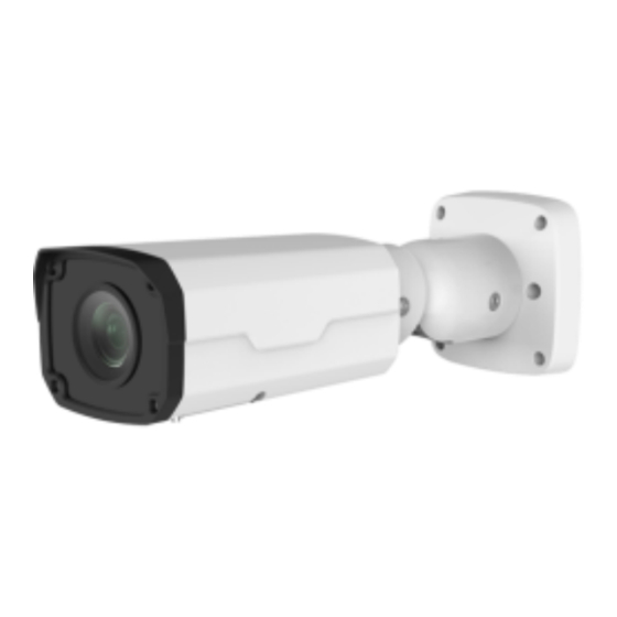
Page 14: Appearance Description
Appearance Description Dimensions and Appearance 86mm (3.39“) 253.4mm (9.98“) ¼ -20UNC Camera Structure All cables are tagged to indicate their functions separately. The tail cable available may vary with the product model. The following examples show cables that are for 12 VDC and 24 VAC. -
Page 15: Cable Connection
Cable Connection Description Description Sun shield Housing 10M/100M Base-TX Video output, adaptive Ethernet interface interface, RJ45 Audio input Audio output Power interface Alarm input VDC) Alarm output Lens IR LED... -
Page 16: Installation
For the latest specifications, see the product datasheet. Installation Hardware Installation Insert the Micro SD Card (Optional) For cameras that support Micro SD, you need to insert the Micro SD card after opening the bottom cover of camera. Do not hot plug the Micro SD card after it is inserted. -
Page 17: Mount Your Camera
Insert the Micro SD card. Micro SD slot Mount Your Camera Locate the positions of the holes. Paste the installation positioning sticker on the wall and align the cross center to the hole on the wall. Lead the cables across the hole on the wall. - Page 18 Drill holes on the wall. Use a Ø 6-6.5 mm drill bit to drill 30 mm- depth guide holes according to the positions marked by the sticker. Mount the plastic anchors of self-tapping screws. Knock the plastic anchors into the guide holes and ensure that they are tightened up.
- Page 19 Loosen the hex fillister-head screw using a 4# hex L-key (that should be purchased separately) to avoid damaging the universal joint. Hex fillister-head screw 4# Hex L-key Mount your camera onto the wall and connect all cables. Lead tapping screws through the guide holes in the base and fix them to the wall by using a screwdriver.
-
Page 20: Start The Camera
Adjust the monitoring direction. Hex fillister-head screw Loosen two hex fillister-head screws using a 4# hex L-key (that should be purchased separately) to avoid damaging the universal joint. Then adjust the camera to the desired monitoring direction. Fasten the screws to finish. Start the Camera Use a power adapter (12 VDC or 24 VAC, not included in the package delivered) to start the camera. -
Page 21: Waterproof Measures
Waterproof Measures Waterproof Components for RJ45 Plug Attach the seal ring to the copper interface. Seal ring Mount the waterproof components. You can crimp the inner wires of the cable with the RJ45 plug first and then cover the waterproof components. You may also cover the waterproof components first. - Page 22 Insert the cylindrical waterproof ring into bolt. Cylindrical waterproof ring Waterproof bolt Insert the cable into the Ethernet copper interface and screw the waterproof bolt in. Screw in the waterproof bolt lid. Bolt lid...
-
Page 23: Waterproof Tail Cable
Finish the waterproof installation. Waterproof Tail Cable Connect the tail cables and then take the following steps to protect the tail cables from water using waterproof tapes. The figures are only for illustration purpose. Connect the tail cables. - Page 24 Protect the connected cables using insulating tapes. Protect other cables using insulating tapes. Wrap all the tail cables together using insulating tapes.
- Page 25 Choose a start point for waterproof tapes. Waterproof tape Protect the tail cables using waterproof tapes.
-
Page 26: Set Your Camera Over The Lan
Avoid short circuit when insulating the cables. Use self adhesive waterproof tapes that will stick together with the twisted cables. Tighten waterproof tapes when wrapping the cables and make sure the cable connections are fully covered. You are recommended to put the waterproof cables in ... -
Page 27: Access Your Camera
Use EZStation to search online cameras automatically. Modify the camera settings if necessary, including its IP address and subnet mask. The default IP address is “192.168.0.13”. The default username is “admin”, and the default password is “123456”. To access your camera from a different subnet, set the ... -
Page 28: System Requirements For Your Pc
System Requirements for Your PC Item Requirements Microsoft Windows 8/Windows 7/Windows XP Operating (32-bit or 64-bit). Microsoft Windows 7 (32-bit) is system recommended. 2.0 GHz or higher, dual-core. Intel i3 CPU or higher is recommended. Memory At least 1 GB. 2 GB (or higher) is recommended. At least 128 MB display memory. -
Page 29: Access Your Camera
Access Your Camera Before you begin, check that: Your camera is operating properly and connected to the network. The PC you are using is installed with Internet Explorer 7.0 or later. IE 8.0 is recommended. Follow these steps to access your camera through the Web interface: Open your browser, input the IP address of your camera (default IP is 192.168.0.13) in the address bar and then press... -
Page 30: Install The Activex
Install the ActiveX The following takes the IE browser as an example to describe the installation steps. Click Download. Click Run. You may also click Save to download the file to your computer first. Close the browser and follow the steps to complete the installation. -
Page 31: Adjust The Display
For your first login with Windows 7, if the system does not prompt you to install ActiveX, follow these steps to turn off UAC: click the Start button, and then click Control Panel. In the search box, type uac, and then click Change User Account Control Settings. - Page 32 BOM: 3101C0BV...
Need help?
Do you have a question about the CI111UNV37 and is the answer not in the manual?
Questions and answers