Acer Veriton 5800 Manual
Hide thumbs
Also See for Veriton 5800:
- Manuel d'utilisation (106 pages) ,
- Manual (106 pages) ,
- Manual do utilizador (106 pages)
Table of Contents
Advertisement
Chapter 1 System Specification...............................................................1
Overview . . . . . . . . . . . . . . . . . . . . . . . . . . . . . . . . . . . . . . . . . 1
Features . . . . . . . . . . . . . . . . . . . . . . . . . . . . . . . . . . . . . . . . . 2
Block Diagram . . . . . . . . . . . . . . . . . . . . . . . . . . . . . . . . . . . . 5
MainBoard Placement . . . . . . . . . . . . . . . . . . . . . . . . . . . . . . 6
Rear I/O Port . . . . . . . . . . . . . . . . . . . . . . . . . . . . . . . . . . . . . . 7
Veriton 5800 Front Panel . . . . . . . . . . . . . . . . . . . . . . . . . . . . 8
Veriton 6800 Front Panel . . . . . . . . . . . . . . . . . . . . . . . . . . . . 9
Veriton 7800 Front Panel . . . . . . . . . . . . . . . . . . . . . . . . . . . 10
Veriton 5800 Rear Panel . . . . . . . . . . . . . . . . . . . . . . . . . . . 11
Veriton 6800 Rear Panel . . . . . . . . . . . . . . . . . . . . . . . . . . . 12
Veriton 7800 Rear Panel . . . . . . . . . . . . . . . . . . . . . . . . . . . 13
System Peripherals . . . . . . . . . . . . . . . . . . . . . . . . . . . . . . . . 14
Acer eRecovery . . . . . . . . . . . . . . . . . . . . . . . . . . . . . . . . . . 16
Acer disc-to-disc recovery . . . . . . . . . . . . . . . . . . . . . . . . . . 18
Hardware Specifications and Configurations . . . . . . . . . . . . 19
Dual Channel . . . . . . . . . . . . . . . . . . . . . . . . . . . . . . . . . . . . 27
Chapter 2 System Utilities......................................................................28
Entering Setup . . . . . . . . . . . . . . . . . . . . . . . . . . . . . . . . . . . 29
Product Informatoin . . . . . . . . . . . . . . . . . . . . . . . . . . . . . . . 31
Standard CMOS Features . . . . . . . . . . . . . . . . . . . . . . . . . . 32
Advanced BIOS Features . . . . . . . . . . . . . . . . . . . . . . . . . . . 35
Advanced Chipset Setup . . . . . . . . . . . . . . . . . . . . . . . . . . . 39
Integrated Peripherals . . . . . . . . . . . . . . . . . . . . . . . . . . . . . 40
Power Management Setup . . . . . . . . . . . . . . . . . . . . . . . . . . 43
PnP/PCI Configuration . . . . . . . . . . . . . . . . . . . . . . . . . . . . . 45
PC Health Status . . . . . . . . . . . . . . . . . . . . . . . . . . . . . . . . . 48
Frequency Control . . . . . . . . . . . . . . . . . . . . . . . . . . . . . . . . 50
Load Default Settings . . . . . . . . . . . . . . . . . . . . . . . . . . . . . . 51
Set Supervisor/User Password . . . . . . . . . . . . . . . . . . . . . . . 52
Save & Exit Setup . . . . . . . . . . . . . . . . . . . . . . . . . . . . . . . . . 53
Exit Without Saving . . . . . . . . . . . . . . . . . . . . . . . . . . . . . . . . 54
Chapter 3 Machine Disassembly and Reassembly.................................55
General Information . . . . . . . . . . . . . . . . . . . . . . . . . . . . . . . 56
VT 5800 Disassembly Procedure . . . . . . . . . . . . . . . . . . . . . 57
VT 6800 Disassembly Procedure . . . . . . . . . . . . . . . . . . . . . 62
VT 7800 Disassembly Procedure . . . . . . . . . . . . . . . . . . . . . 67
Chapter 4 Troubleshooting.....................................................................72
Power-On Self-Test (POST) . . . . . . . . . . . . . . . . . . . . . . . . . 73
POST Error Messages List . . . . . . . . . . . . . . . . . . . . . . . . . . 79
Error Symptoms List . . . . . . . . . . . . . . . . . . . . . . . . . . . . . . . 81
Undetermined Problems . . . . . . . . . . . . . . . . . . . . . . . . . . . . 86
Chapter 5 Jumper and Connector Information......................................87
Connectors Introduction......................................................... 87
Chapter 6 FRU(Field Replaceable Unit) List.......................................104
Exploded Diagram . . . . . . . . . . . . . . . . . . . . . . . . . . . . . . . 105
Parts . . . . . . . . . . . . . . . . . . . . . . . . . . . . . . . . . . . . . . . . . . 106
Appendix A Model Definition and Configuration.................................107
Appendix B Test Compatible Component.............................................108
Microsoft Windows XP Home Environment Test . . . . . . . . 109
Appendix C Online Support Information..............................................121
1
Advertisement
Table of Contents
Troubleshooting

Related Manuals for Acer Veriton 5800


Summary of Contents for Acer Veriton 5800
-
Page 1: Table Of Contents
System Peripherals ....... . 14 Acer eRecovery ........16 Acer disc-to-disc recovery . -
Page 2: Chapter 1 System Specification
Dual channel DDR2 memory slots, one parallel ATA port, four serial ATA2 prots, and onboard Gigabit LAN, onboard Audio function. There are three knids of chassis for Veriton series: Veriton 7800 for Mini-tower, Veriton 5800 for Desktop and Veriton 6800 for Micro-tower which can fulfill all segment customers: expandability, middle-to-heavy performance, and space saving. -
Page 3: Features
Features Socket Type : Intel Socket T Supports Intel Pentium 4 Prescott 775 / Smithfield FSB 800/1066MHz Supports Intel Celeron Prescott 775 / FSB 533MHz Pentium 4 2.66GHz ~3.8GHz speed Celeron D2.53GHz ~ 3.2GHz L2 Cache varies with CPU Chipset Northbridge: Intel Lakeport-G Southbridge: Intel ICH7 Memory... -
Page 4: System Led Definition
Audio Codec : Realtek ALC880 (HD Codec) One UAJ (Universal Audio Jack) support (rear only) Remark UAJ : UAJ not only provides the ideal solution for multi-media and also user-friendliness for audio speaker installation. 7.1 Channel Audio Support Reserved disable function on BIOS side. Default is enabled. Controller : PCI-E Giga LAN chip with manageability function LAN Chip : Marvell 88E8052 Should be worked under 10/100/1000 Mbs environment... - Page 5 1 PATA IDE Slots 4 SATA2 IDE Slots 2 2*5 pin Intel FPIO sepecification USB pin connectors 1 2*5 pin Intel FPIO spec. Microphone In/Headphone Out pin connectors 1 2nd serial port 1 CD-In 4pin connector (CD-ROM Audio Input) 1 4 pin CPU Fan connector with linear circuit 1 3 pin System FAN connectors with linear circuit 1 Intrusion ALarm connector 1 24pin/4pin ATX interface PS3/PS2 SPS connector...
-
Page 6: Block Diagram
Block Diagram PCI-ECLK (100MHz) 1 PCI Express x 1 Port PCI-ECLK(100MHz) PCI Express x1 Bus 2 PCI PCICLK (33MHz) Chapter 1 LGA775 Processor Host Interface PCI Express x16 Intel 945G PCI Bsu Intel ICH7 88E8052 RJ45 CODEC CPUCLK+/-(200/133MHz) DDRII 667/533/400MHz DIMM Dual Channel Memory MCHCLK (133/200MHz) 66MHz... -
Page 7: Mainboard Placement
MainBoard Placement KB_MS AUDIO1 PCIE_12V AUDIO2 88E8052 CD_IN PCIE_1 SPDIF CODEC F-AUDIO CPU_FAN LGA775 ATX_12V Intel 945G PCIE_16 PCI1 BIOS PCI2 RESV2 RECOVERY RESV1 SYS_FAN COMB F_USB1 LOCKER LOCK_RST LPC47M182 ICH7 CLR_CMOS F_USB2 F_PANEL Chapter 1... -
Page 8: Rear I/O Port
Rear I/O Port Item Name PS/2 Keyboard and PS/2 Mouse Connector LPT Port (Parallel Port) COM (Serial Port) VGA Port USB Ports LAN Port Line In Line Out MIC In Rear Speaker Out Center/Subwoofer Speaker Out Side Speaker Out Chapter 1 Description To install a PS/2 port keyboard and mouse, plug the mouse to the upper port (green) and the keyboard to the ower port (purple). -
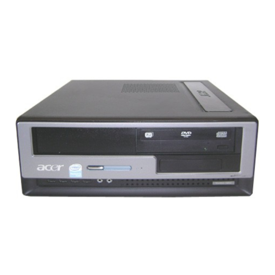
Page 9: Veriton 5800 Front Panel
Veriton 5800 Front Panel Optical Device Microphone-in jack USB ports Indicators Description Description Floppy drive Speaker-out/line-out port One Button Recovery hole Power button Chapter 1... -
Page 10: Veriton 6800 Front Panel
Veriton 6800 Front Panel Optical Device Microphone-in jack USB ports Power button NOTE: The specifications above are for reference only. The exact configuration of your PC depends on the model purchased. Chapter 1 Description Description Floppy drive Speaker-out/line-out port Indicators... -
Page 11: Veriton 7800 Front Panel
Veriton 7800 Front Panel Optical Device Microphone-in jack USB ports Power button Description Description Floppy drive Speaker-out/line-out port Indicators Chapter 1... -
Page 12: Veriton 5800 Rear Panel
Veriton 5800 Rear Panel Power supply Voltage selector switch PS/2 Keyboard port Printer connector USB 2.0 ports Audio jack Chassis lock pad Chapter 1 Description Description Power cord socket PS/2 mouse port Serial port Monitor connector RJ-45 Ethernet connector Expansion slots... -
Page 13: Veriton 6800 Rear Panel
Veriton 6800 Rear Panel Power supply Voltage selector switch PS/2 Keyboard port Printer connector USB 2.0 ports Audio jack Chassis lock pad Description Description Power cord socket PS/2 mouse port Serial port Monitor connector RJ-45 Ethernet connector Expansion slots Chapter 1... -
Page 14: Veriton 7800 Rear Panel
Veriton 7800 Rear Panel Power supply Voltage selector switch PS/2 Keyboard port Printer connector USB 2.0 ports Audio jack Chassis lock pad Audio Jack Function Table Color/Use Headphone Blue Line-in Green Headphone Pink Mic-in Orange Center&woofer Black Rear Gray Side Chapter 1 Description 1.1 CH... -
Page 15: System Peripherals
System Peripherals The Aspire T630 and AcerPower F3 computer consist of the system itself, and system peripherals, like a mouse, keyboard and a set of speakers (optional). This section provides a brief description of the basic system peripherals. Mouse (PS/2 or USB, manufacturing option) The included mouse is a standard two-button wheel mouse. - Page 16 Speakers For systems bundled with speakers, before powering on the system, connect the speaker cable to the audio out (external speaker) port on the back panel of the system. For more detailed information about the speakers, please refer to the included operating instructions. NOTE: speakers are optional and the appearance might be different depending on the actual product.
-
Page 17: Acer Erecovery
Acer eRecovery Acer eRecovery is a tool to quickly backup and restore the system. Users can create and save a backup of the current system configuration to hard drive, CD, or DVD. Acer eRecovery consists of the following functions: Create backup... -
Page 18: Change Password
In the Recovery settings window, select Reinstall applications/drivers and click Next. Select the desired driver/application and follow the instructions on screen to re-install. At first launch, Acer eRecovery prepares all the needed software and may take few seconds to bring up the software content window. -
Page 19: Acer Disc-To-Disc Recovery
It is important to back up all data files before you use this option. Restart the system. While the Acer logo is showing, press <Alt>+<F10> at the same time to enter the recovery process. The message "The system has password protection. Please enter 000000:" is displayed. -
Page 20: Hardware Specifications And Configurations
Hardware Specifications and Configurations System Board Major Chip Item System Core Logic Super I/O Controller LAN Controller Memory Controller E-IDE Controller RJ45 Controller Audio Controller VGA Controller Keyboard Controller Processor Item Type Slot Speed Bus Frequency Voltage BIOS Item BIOS code programmer BIOS version BIOS ROM size BIOS ROM package... - Page 21 BIOS Hotkey List Hotkey System Memory Item Memory Slot Number Supported Memory Size per Slot Supported Maximum Memory Size Supported Memory Speed Supported memory voltage Support memory module package Support to parity check feature Support to Error Correction Code (ECC) feature Memory module combinations VRM (Voltage Regulator Module)
- Page 22 LAN Interface Item LAN Controller LAN Controller Resident Bus LAN Port Function Control IDE Interface Item IDE Controller IDE Controller Resident Bus Number 40 pin PATA slot Device Type Support Transfer Rate Support ATA Mode Number STAT IDE slot Device Type Support Supports LS-120 Supports bootable CD-ROM Function Control...
- Page 23 USB Port Item Universal HCI Controller Number of the connectors Location USB Class Wake-up Event Specifications Device Power Button PS2 Keyboard USB Keyboard WOR (wake on Ring) RTC (real time clock) Thermal Design Item Thermal Design Memory Address Map Address 0000000 - 009FFFF 00A0000-00BFFFF 00C0000-00CFFFF...
- Page 24 Memory Address Map Address 00F0000-00FFFFF 0100000-0F9FFFF 0FA0000-0FFFFFF 1000000-FFFFFFF PCI INTx# and IDSEL Assignment Map PCI INTx # INTA# ADIMM-slot INTB# PCI-Slot1 INTC# PCI-Slot2 I/O Address Map Hex Range 000-01F 020-021 040-043 060-060 061-061 070-071 080-08F 0A0-0A1 0C0-0DF 0F0-0FF 170-177 1F0-1F7 278-27F 2F8-2FF 378-37F...
- Page 25 IRQ Assignment Map IRQx IRQ0 Timer IRQ1 Keyboard IRQ2 Reserved IRQ3 Serial Port 2 IRQ4 Serial Port 1 IRQ5 Reserved IRQ6 Floppy Disk IRQ7 Parallel Port IRQ8 Real Time Clock IRQ9 IRQ10 IRQ11 IRQ12 PS/2 Mouse IRQ13 Numeric Processor IRQ14 Embedded Hard Disk IRQ15 Reserved...
- Page 26 Environmental Requirements Item Non-operating (packed) Shock Operating Drop Test Drop Test Definition The protection ability of packing & cushion must be capable of withstanding, with no physical or functional demage, mechanical impact from height-specific drops. Test Standard Package Cross Weight 0~9.1 0~20 9.1~18.2...
-
Page 27: Power Management Function ( Acpi Support Function)
Power Management Function ( ACPI support function) Device Standby Mode Independent power management timer for hard disk drive devices (0-15 minutes, time step=1 minute). Hard disk drive goes into Standby mode (for ATA standard interface). Disable V-sync to control the VESA DPMS monitor. Resume method: device activated (Keyboard for DOS, keyboard &... -
Page 28: Dual Channel
Dual Channel VT x800 series support the Dual Channel Technology. After operating the dual channel technology, the bandwidth of memory bus will add double up to 4GB/s. The mainboard inculdes 4 DIMM slots, and each channel has two DIMM sockets as following: Channel A : DDR1, DDR3 Channel B : DDR2 , DDR4 If you want to operate the Dual Channel Technology, please note the following explanations due to... -
Page 29: Chapter 2 System Utilities
System Utilities BIOS (Basic Input and Output System) includes a CMOS SETUP utility which allows user to configure required setting or to active certain system features. The CMOS SETUP saves the configuration in the CMOS SRAM of the mainboard. When the power is turned off, the battery on the mainboard supplies the necessary power to the CMOS SRAM. -
Page 30: Entering Setup
Entering Setup Once enter Award BIOS CMOS Setup Utility, the Main Menu (as figure below) will appear on the screen. Use arrow keys to select among the items and press <Enter> to accept or enter the sub-menu. Note: If you can’t find the setting you want, please press “Alt+F4” to search the advanced option hidden. - Page 31 Parameter Product Information Standard CMOS Features Advanced BIOS Features Integrated Peripherals Power Management Setup PnP/PCI Configuration PC Health Status Load Default Settings Set Supervisor Password Set User Password Save & Exit Setup Exit Without Saving Hidden Setting Advanced Chipset Features Chapter 2 Description This page shows the relevant information of the mainboard...
-
Page 32: Product Informatoin
Product Informatoin CMOS Setup Utility-Copyright © 1984-2004 Award Software Product Name System S/N Main Board ID Main Board S/N System BIOS Version SMBIOS version System BIOS ID BIOS Release Date : Move Enter: Select F5: Previous Values Parameter Product Name This item lists the product name System S/N This item lists the system serial number... -
Page 33: Standard Cmos Features
Standard CMOS Features CMOS Setup Utility-Copyright © 1984-2004 Award Software Date (mm:dd:yy) Time (hh:mm:ss) IDE Channel 0 Master IDE Channel 0 Slave IDE Channel 1 Master IDE Channel 1 Slave Drive A Halt On Base Memory Extended Memory Total Memory : Move Enter: Select F5: Previous Values... - Page 34 The following table describes the parameters found in this menu: Parameter Date Lets you set the date following the weekday- month-day-year format Time Lets you set the time following the hour-minute- second format IDE channel 0/1 Master, Allows you to configure the hard disk drive Slave connected to the master port of IDE channel.
- Page 35 Parameter Halt On This parameter enables you to control the system stops in case of Power On Self Test errors (POST) Chapter 2 Description No Errors : The system boot will not stop for any error that may be detected and you will be prompted All Errors : Whenever the BIOS detects a non-fatal error the system will be stopped...
-
Page 36: Advanced Bios Features
Advanced BIOS Features The following screen shows the Advanced BIOS Features: CMOS Setup Utility-Copyright © 1984-2005 Award Software Virus Warning CPU L1 & L2 Cache Silent Boot Configuration Table Hard Disk Boot Priority Quick Power On Self Test First Boot Device Second Boot Device Third Boot Device Boot Other Device... - Page 37 Alt+F4 : Hidden Setting CMOS Setup Utility-Copyright © 1984-2004 Award Software Virus Warning CPU L1 & L2 Cache Silent Boot Configuration Table Hard Disk Boot Priority Quick Power On Self Test First Boot Device Second Boot Device Third Boot Device Boot Other Device Boot Up NumLock Status Gate A20 Option...
- Page 38 Parameter Virus Warning This feature allows you to enable the VIRUS warning function for IDE Hard Disk boot sector protection. If this function is enabled and there is someone attempt to write data into this area, BIOS will show a warning message on screen and the alarm will beep.
- Page 39 Parameter Intel XD bit When Disabled, forces the NX feature flag to always return 0. Init DIsplay First Select the first initation of the monitor display from different type of VGA card. Chapter 2 Description Disabled Onboard/PEG Options...
-
Page 40: Advanced Chipset Setup
Advanced Chipset Features CMOS Setup Utility-Copyright © 1984-2005 Award Software CAS Latency Time DRAM RAS# to CAS# Delay DRAM RAS# Precharge Active to Precharge Delay Refresh Mode Select ** On-Chip VGA Setting ** DVMT Mode On-chip Video Memory Size : Move Enter: Select F5: Previous Values Parameter... -
Page 41: Integrated Peripherals
Integrated Peripherals All onboard peripherals can be set up through this menu. CMOS Setup Utility-Copyright © 1984-2005 Award Software On-Chip Primary PCI IDE On-Chip Secondary PCI IDE [Enabled] On-Chip SATA Mode x PATA IDE Set to SATA Port0/2 Set to SATA Port1/3 Set to USB Controller USB 2.0 Controller... - Page 42 Parameter On-Chip Primary/Secondary PCI IDE On-Chip SATA Mode USB 2.0 Controller USB Controller USB Keyboard Support USB Mouse Support Azalia Codec Onboard H/W LAN Onboard LAN Boot ROM PS2 Keyboard Wakeup PS2 Mouse Wakeup Onboard Serial Port 1/2 UART Mode Select Description This feature allows you to enable or disable the on-chip IDE port.
- Page 43 Parameter Parallel Port Mode Chapter 2 Description This feature allows to select the Parallel Port Mode. Options EPP1.9+SPP EPP1.9+ECP PRINTER EPP1.7+SPP EPP1.7+ECP...
-
Page 44: Power Management Setup
Power Management Setup The Power Management menu lets you configure your system to most effectively save energy while operating in a manner consistent with your own style of computer use. CMOS Setup Utility-Copyright © 1984-2005 Award Software ACPI function ACPI Suspend Type Soft-Off by PWR-BTTN AC BACK Function PME Event Wake Up... - Page 45 Parameter ACPI Function This item allows you to enable or disable the ACPI function ACPI Suspend Type This item specifies the power saving modes for ACPI function. S1(POS): The S1 sleep mode is a low power state. In this state, no system context (CPU or chipset) is lost and hardware maintains all system context.
-
Page 46: Pnp/Pci Configuration
PnP/PCI Configuration CMOS Setup Utility-Copyright © 1984-2005 Award Software PCI1 IRQ Assignment PCI2 IRQ Assignment : Move Enter: Select F5: Previous Values Alt+F4 : Hidden Setting CMOS Setup Utility-Copyright © 1984-2005 Award Software Resources Controlled By x IRQ Resources PCI Latency Timer(CLK) PCI1 IRQ Assignment PCI2 IRQ Assignment : Move... - Page 47 CMOS Setup Utility-Copyright © 1984-2005 Award Software Resources Controlled By IRQ Resources PCI Latency Timer(CLK) PCI1 IRQ Assignment PCI2 IRQ Assignment : Move Enter: Select F5: Previous Values Chapter 2 PnP/PCI Configurations [Manual] [Press Enter] [32] [Auto] [Auto] +/-/PU/PD: Value F10:Save F7: Default Setting Item Help...
- Page 48 IRQ Resource CMOS Setup Utility-Copyright © 1984-2005 Award Software IRQ-3 assigned to IRQ-4 assigned to IRQ-5 assigned to IRQ-7 assigned to IRQ-9 assigned to IRQ-10 assigned to IRQ-11 assigned to IRQ-12 assigned to IRQ-14 assigned to IRQ-15 assigned to : Move Enter: Select +/-/PU/PD: Value F5: Previous Values Parameter PCI1/2 IRQ Assignment...
-
Page 49: Pc Health Status
PC Health Status CMOS Setup Utility-Copyright © 1984-2005 Award Software Chassis Opened Warning Chassis Opened Shutdown Temperature VCore +1.5V + 3.3V +12V Current CPU Temperature Current System Temperature Current CPU Fan Speed Current System Fan Speed CPU Smart FAN Control : Move Enter: Select +/-/PU/PD: Value F5: Previous Values Chapter 2... - Page 50 Alt+F4 : Hidden Setting CMOS Setup Utility-Copyright © 1984-2005 Award Software Chassis Opened Warning Chassis Opened Shutdown Temperature VCore +1.5V + 3.3V +12V Current CPU Temperature Adjust CPU Temperature CPU Temperature Offset Current System Temperature Adjust System Temperature System Temperature Offset Current CPU Fan Speed Current System Fan Speed CPU Smart Fan Function...
-
Page 51: Frequency Control
Frequency Control CMOS Setup Utility-Copyright © 1984-2005 Award Software SpreadSpectrum System Memory Multiplier Memory Frequency(Mhz) : Move Enter: Select +/-/PU/PD: Value F5: Previous Values Parameter SpreadSpectrum System Memory Multiplier Chapter 2 Frequency Control [Enabled] [Auto] F10:Save ESC: Exit F7:Default Setting Description This feature allows to enable/disable the Spread Spectrum modulate. -
Page 52: Load Default Settings
Load Default Settings Selecting the field loads the factory defaults for BIOS and Chipset Features which the system automatically. detects. Chapter 2... -
Page 53: Set Supervisor/User Password
Set Supervisor/User Password When this function is selected, the following message appears at the center of the screen to assist you in creating a password. The access rights and permission associated with the Supervisor password are higher than those os a regular User password. -
Page 54: Save & Exit Setup
Save & Exit Setup Highlight this item and press <Enter> to save the changes that you have made in the Setup Utility and exit the Setup Utility. When the Save and Exit dialog box appears, press <Y> to save and exit, or press <N> to return to the main menu. -
Page 55: Exit Without Saving
Exit Without Saving Highlight this item and press <Enter> to discard any changes that you have made in the Setup Utility and exit the Setup Utility. When the Exit Without Saving dialog box appears, press <Y> to discard changes and exit, or press <N> to return to the main menu. -
Page 56: Chapter 3 Machine Disassembly And Reassembly
Machine Disassembly and Replacement This chapter will guide you how to disassemble and Reassemble the VT5800/6800/7800. To disassemble the computer, you need the following tools: Wrist grounding strap and conductive mat for preventing electrostatic discharge. Wire cutter. Phillips screwdriver (may require different size). NOTE: The screws for the different components vary in size. -
Page 57: General Information
General Information Before You Begin Before proceeding with the disassenbly procedure, make sure that you do the following: Turn off the power to the system and all peripherals. Unplug the AC adapter and all power and signal cables from the system. Chapter 3... -
Page 58: Vt 5800 Disassembly Procedure
VT 5800 Disassembly Procedure This section tells you how to disassemble the system when you need to perform system service. Please also refer to the disassembly video, if available. CAUTION: Before you proceed, make sure you have turned off the system and all peripherals connected to it. Opening the System Place the system unit on a flat, steady surface. - Page 59 Removing Cables Disconnect the HDD SATA cables. Disconnect the USB1&2 cables. Disconnect the system fan cable. Disconnect the Recovery switch cable. Disconnect HDD SATA1&2 cable. Disconnect the LED cable assy and Power-switch cable. Disconnect the power cable and IDE cable of the ODD. Chapter 3...
- Page 60 Disconnect the power cable and IDE cable of the FDD. Disconnect the power cable and IDE cable of the SATA HDD. 10. Disconnect the main ATX power cable as shown. 11. Disconnect the IDE cables from the mainboard. Removing the ODD/FFD/HDD Release the ODD latch and pull the ODD out as shown.
-
Page 61: Removing The Heatsink Module
Press the left and right latch to release the latch and pull the HDD out as shown. Removing the Heatsink Module Remove the four screws securing the heatsink module and remove it. Removing the Memory Press the latch on the left and right sides to pup out the memory and remove it. Removing the System Fan Remove the four screws securing the system fan and remove it. -
Page 62: Removing The Usb Module
Removing the System Power Remove the four screws securing the system power and remove it. Removing the USB Module Remove the screw securing the usb module and detach it as shown. Removing the LED Module Remove the screw securing the LED module and detach it as shown. Chapter 3... -
Page 63: Vt 6800 Disassembly Procedure
VT 6800 Disassembly Procedure Opening the System Place the system unit on a flat, steady surface. Press the latch and slide the side door out as shown. Removing the Front Panel and Top Cover Release the three latches and remove the front panel and top cover. Removing the VGA Card Release the PCI lock then remove it. -
Page 64: Removing The Cables
Removing the Cables Disconnect following connectors from the mainboard. Disconnect SATA HDD connectors from the mainboard. Disconnect the power switch and LED cable as shown. Disconnect following connectors from the mainboard. Chapter 3... - Page 65 Disconnect the ODD and FDD power cables. Disconnect the SATA HDD cables. Disconnect the ODD and FDD IDE cables. Removing ODD/FDD/HDD Press the ODD latch and pull the ODD out. Press the FDD latch and pull the FDD out. Press the HDD latch and pull the HDD out. Chapter 3...
-
Page 66: Removing The Power Supply
Removing the Heatsink Module Remove the four screws securing the heatsink module and remove it. Removing the Memory Press the latch on the left and right sides to pup out the memory and remove it. Removing the System Fan Remove the four screws securing the system fan and remove it. Removing the Mainboard Remove the eight screws securing the mainboard and remove it. - Page 67 Removing the SPDIF Board and Intrusion Switch Remove the screw securing the SPDIF board and release the intrusion switch. Removing the USB Module Remove the screw securing the USB module and remove it. Chapter 3...
-
Page 68: Vt 7800 Disassembly Procedure
VT 7800 Disassembly Procedure Opening the System Place the system unit on a flat, steady surface. Press the latch and slide the side door out as shown. Removing the Front Panel and Top Cover Release the three latches and remove the front panel and top cover. Removing the VGA Card Release the PCI-Lock as shown. - Page 69 Removing the Cables Disconnect following connectors from the mainboard. Disconnect SATA HDD connectors from the mainboard. Disconnect the power switch and LED cable as shown. Disconnect following connectors from the mainboard. Chapter 3...
- Page 70 Disconnect the ODD and FDD power cables. Disconnect the SATA HDD cables. Disconnect the ODD and FDD IDE cables. Removing ODD/FDD/HDD Press the ODD latch and pull the ODD out. Press the FDD latch and pull the FDD out. Press the HDD latch and pull the HDD out. Chapter 3...
- Page 71 Removing the Heatsink Module Remove the four screws securing the heatsink module and remove it. Removing the Memory Press the latch on the left and right sides to pup out the memory and remove it. Removing the System Fan Remove the four screws securing the system fan and remove it. Removing the Mainboard Remove the eight screws securing the mainboard and remove it.
- Page 72 Removing Intrusion Switch Remove the two screws securing the intrusion switch and remove it. Removing USB Module Release USB board with its upper bracket. Chapter 3...
-
Page 73: Chapter 4 Troubleshooting
Chapter 4 Troubleshooting This chapter provides troubleshooting information for the VT5800/6800/7800 Power-On Self-Test (POST) Index of Error Message Index of Error Symptoms Undetermined Problems Chapter 4... -
Page 74: Power-On Self-Test (Post)
Power-On Self-Test (POST) Each time you turn on the system, the Power-on Self Test (POST) is initiated. Several items are tested during POST, but is for the most part transparent to the user. The Power-On Self Test (POST) is a BIOS procedure that boots the system, initializes and diagnoses the system components, and controls the operation of the power-on password option. - Page 75 Checkpoint Initial Superio_Early _Init switch Reserved 1. Blank out screen 2. Clear CMOS error flag Reserved 1. Clear 8042 interface 2. Initialize 8042 self-test 1. Test special keyboard controller for Winbond 977 series Super I/O chips. 2. Enable keyboard interface. Reserved 1.
- Page 76 Checkpoint 1. Check validity of RTC value: e.g. a value of 5Ah is an invalid value for RTC minute. 2. Load CMOS settings into BIOS stack. If CMOS checksum fails, use default value instead. 3. Prepare BIOS resource map for PCI & PnP use. If ESCD is valid, take into consideration of the ESCD’s legacy information.
- Page 77 Checkpoint Test 8254. Reserved Test 8259 interrupt mask bits for channel 1 Reserved Test 8259 interrupt mask bits for channel 2 Reserved Reserved Test 8259 functionality Reserved Reserved Reserved Initialize EISA slot Reserved 1. Calculate total memory by testing the last double word of each 64K. 2.
- Page 78 Checkpoint 1. Initialize Init_Onboard_Super_IO switch. 2. Initialize Init_Onboard_AUDIO switch. Reserved Reserved Okay to enter Setup utility; i.e. not until this POST stage can users enter the CMOS setup utility. Reserved Reserved Reserved Reserved Initialize PS/2 Mouse Reserved Prepare memory size information for function call: INT 15h ax=E820h Reserved Turn on L2 cache...
- Page 79 Checkpoint Reserved 1. Switch back to text mode if full screen logo is supported. -If errors occur, report errors & wait for keys -If no errors occur or F1 key is pressed to continue: Clear EPA or customization logo. Reserved Reserved 1.
-
Page 80: Post Error Messages List
POST Error Messages List If you cannot run the diagnostics program tests but did receive a POST error message, use “POST Error Messages List” to diagnose system problems. If you did not receive any error message, look for a description of your error symptoms in “Error Symptoms List”... - Page 81 BIOS Messages Keyboard Error Or No Keyboard Present Keyboard is locked out - Unlock the key Memory Test: Memory test fail Override enabled - Defaults loaded Press TAB to show POST screen Primary master hard disk fail Primary slave hard disk fail Secondary master hard disk fail Secondary slave hard disk fail Chapter 4...
-
Page 82: Error Symptoms List
Error Symptoms List NOTE: To diagnose a problem, first find the error symptom in the left column. If directed to a check procedure, replace the FRU indicated in the check procedure. If no check procedure is indicated, the first Action/ FRU listed in right column is the most likely cause. - Page 83 Error Symptom Diskette drive read/write error. Diskette drive LED comes on for more than 2 minutes when reading data. Diskette drive LED fails to light, and the drive is unable to access for more than 2 minutes. Diskette drive test failed. NOTE: Ensure hard disk drive is configured correctly in BIOS Setup, cable/jumper are set correctly before diagnosing any hard disk drive problems.
- Page 84 Error Symptom CD/DVD-ROM drive does not read and there are no messages are displayed. CD/DVD-ROM drive can play audio CD but no sound output. Real-time clock is inaccurate. Audio software program invokes but no sound comes from speakers. Modem ring cannot wake up system from suspend mode.
- Page 85 Error Symptom Display problem not listed above (including blank or illegible monitor). Chapter 4 Action/FRU 1. “Monitor" 2. Load default settings (if screen is readable). 3. Main board...
- Page 86 Error Symptom Execute “Load BIOS Default Settings” in BIOS Setup to confirm ports presence before diagnosing any parallel/serial ports problems. Serial or parallel port loop-back test failed. Printing failed. Printer problems. Some or all keys on keyboard do not work. Pressing power switch does not turn off system.
-
Page 87: Undetermined Problems
Check all cables and connectors for proper installation. If the jumpers, switches and voltage settings are correct, remove or disconnect the following, one at a time: 10. Non-Acer devices External devices Any adapter card (modem card, LAN card or video card, if installed) -
Page 88: Chapter 5 Jumper And Connector Information
Jumper and Connector Information Connectors Introduction Item Description ATX_12V ATX (Power Connector) PCIE_12V CPU_FAN SYS_FAN SATA0 / SATA1 / SATA2 / SATA3 F_PANEL F_AUDIO Chapter 5 Item Chapter 5 Description CD_IN F_USB1 / F_USB2 / R_USB COMB SPDIF CLR_CMOS RECOVERY RESV1 / RESV2... - Page 89 ATX_12V/ATX (Power Connector) With the use of the power connector, the power supply can supply enough stable power to all the components on the mainboard. Before connecting the power connector, please make sure that all components and devices are properly installed. Align the power connector with its proper location on the mainboard and connect tightly. The ATX_12V power connector mainly supplies power to the CPU.
- Page 90 Illustration Chapter 5 PIN No. 3.3V 3.3V Power Good 5V SB(stand by +5V) +12V +12V 3.3V(Only for 24pins ATX) 3.3V -12V PS_ON(soft On/Off) Definition...
- Page 91 PCIE_12V Illustration Pin No. Definition Chapter 5...
- Page 92 CPU FAN / SYS FAN (Cooler Fan Power Connector) The cooler fan power connector supplies a +12V power voltage via a 3-pin/4-pin (only for CPU FAN) power connector and possesses a foolproof connection design. Most coolers are designed with color-coded power connector wires. A red power connector wire indicates a positive connection and requires a +12V power voltage.
- Page 93 FDD (Floppy Connector) The FDD connector is used to connect the FDD cable while the other end of the cable connects to the FDD drive. The types of FDD drives supported are: 360KB, 720KB, 1.2MB, 1.44MB and 2.88MB. Please connect the red power connector wire to the pin1 position. Chapter 5...
- Page 94 IDE (IDE Connector) An IDE device connects to the computer via an IDE connector. One IDE connector can connect to one IDE cable, and the single IDE cable can then connect to two IDE devices (hard drive or optical drive). If you wish to connect two IDE devices, please set the jumper on one IDE device as Master and the other as Slave (for information on settings, please refer to the instructions located on the IDE device).
- Page 95 SATA0 / SATA1 / SATA2 / SATA3 (Serial ATA Connector) Serial ATA can provide 150MB/s transfer rate. Please refer to the BIOS setting for the Serial ATA and install the proper driver in order to work properly. Illustration Pin No. Definition Chapter 5...
- Page 96 F_PANEL (Front Panel Jumper) Please connect the power LED, PC speaker, reset switch and power switch etc. of your chassis front panel to the F_PANEL connector according to the pin assignment below. Item HD (SATA Hard Disk Active LED) RES (Reset Switch) PW (Power Switch) MSG (Message LED/Power/Sleep LED)
- Page 97 PWR_LED PWR_LED is connect with the system power indicator to indicate whether the system is on/off. It will blink when the system enters suspend mode. F_AUDIO (Front Audio Panel Connector) If you want to use Front Audio connector, you must remove 5-6, 9-10 Jumper. In order to utilize the front audio header, your chassis must have front audio connector.
- Page 98 HD Audio Pin No. MIC Power Line Out(R) No Pin Lint Out(L) AC’97 Audio Pin No. MIC2_L MIC2_R -ACZ_DET Line2_R FSENSE1 FAUOIO_JD No Pin LINE2 (L) FSENSE2 NOTE: HD Audio is the default setting for this connector. To enable AC’97 Audio, from BIOS settings, set Front Panel Type under Integrated Peripherals to AC97.
- Page 99 CD_IN (CD In Connector, Black) / AUX_IN (AUX In Connector, White) Connect CD-ROM or DVD-ROM audio out to the CD_IN connector. Connect other device (such as PCI TV Tunner audio out) to the AUX_IN connector. CD-IN Illustration CD_IN (Black) Pin No. Definition CD-L CD -R...
- Page 100 F_ USB1 / F_USB2 / R_USB (Front / Rear USB Connector) Be careful with the polarity of the front USB connector. Check the pin assignment carefully while you connect the front USB cable, incorrect connection between the cable and connector will make the device unable to work or even damage it.
- Page 101 COMB (Serial Port Connector) Be careful with the polarity of the COM connector. Check the pin assignment carefully while you connect the COM cable, incorrect connection between the cable and connector will make the device unable to work or even damage it. Illustration Pin No.
- Page 102 SPDIF (SPDIF In / Out) The SPDIF output is capable of providing digital audio to external speakers or compressed AC3 data to an external Dolby Digital Dicoder. Use this feature only when your stereo system has digital input function. Use SPDIF IN feature when your device has digital output function.
- Page 103 Illustration CL(Chassis Intrusion, Case Open) This 2-pin connector allows your system to enable or disable the “Case Open” item in BIOS, if the system case begin remove. Illustration Definition Open : Normal Short : Clear CMOS Pin No. Definition Signal Chapter 5...
-
Page 104: How To Erase Cmos
BAT(Battery) Illustration How to erase CMOS Turn OFF the computer and unplug the power cord. Remove the battery, wait for 30 seconds. Re-install the battery. Plug the power cord and turn ON the computer. Chapter 5 Definition Danger of explosion if battery is incorrectly replaced. -
Page 105: Chapter 6 Fru(Field Replaceable Unit) List
Chapter 6 FRU (Field Replaceable Unit) List This chapter gives you the FRU (Field Replaceable Unit) listing in global configurations of VT 5800/6800/7800 Refer to this chapter whenever ordering for parts to repair or for RMA (Return Merchandise Authorization). Chapter 6... -
Page 106: Exploded Diagram
Exploded Diagram Item Description TOP COVER FRONT BEZEL HDD LOCK SLIDE FDD LOCK SLIDE ODD LOCK SLIDE RIGHT COVER USBs CHASSIS DISASSEMBLY POWER SUPPLY LEFT COVER MAINBOARD Chapter 6... -
Page 107: Parts
FRU parts for repair and service of customer machines. NOTE: To scrap or to return the defective parts, you should follow the local government ordinance or regulations on how best to dispose it, or follow the rules set by your regional Acer office on how to return it. -
Page 108: Appendix A Model Definition And Configuration
The VT5800/ 6800/ 7800 Model No. Define: Trade Mark: Brand Name: Acer Description: Support P4 LGA775 CPU, Intel 945G+ICH7, DDR2, Gigabit LAN, HD codec (with IO shielding and CPU RM) Model No: B2-K Product Name: Veriton 5800/ 6800/ 7800 Appendix A Appendix A... -
Page 109: Appendix B Test Compatible Component
Appendix B Test Compatible Components VT5800/VT6800/VT7800 compatibility is tested and verified by Acer’s internal testing department. All of its system functions are tested under the environments of Windows XP Home. Appendix B... -
Page 110: Microsoft Windows Xp Home Environment Test
Microsoft Windows XP Home Environment Test COMPONENTS Support P4 LGA775 CPU, Intel 945G+ICH7, DDR2, Gigabit LAN, HD codec, 1394 (with IO shielding Gigabyte and CPU RM) P4 670 (3.8G 2M 800FSB) P4 660 (3.6G 2M 800FSB) P4 650 (3.4G 2M 800FSB) P4 640 (3.2G 2M 800FSB) P4 630 (3.0G 2M 800FSB) P4 570 (3.8G 1M 800FSB) (E-0) - Page 111 COMPONENTS SP X600Pro 9C45 256MB 128bit TVO+DVI+DSUB PAL w/ATX BKT SP X600Pro 9C45 256MB 128bit TVO+DVI+DSUB NTSC w/ATX SP X600Pro 8C45 128MB 128bit TVO+DVI+DSUB PAL w/ATX BKT SP X600Pro 8C45 128MB 128bit TVO+DVI+DSUB NTSC w/ATX Leadtek LTK LR2A22 GF6600 256MB 128bit TVO+DVI+DSUB PAL w/ ATX BKT LTK LR2A22 GF6600 256MB...
- Page 112 COMPONENTS Nanya DDR2 400 256MB Unb. DDRII400 512MB , CL4 Unb. DDRII400 1GB, CL4 Unb. DDRII533 256MB , CL4 Unb. DDRII533 512MB CL4 Unb. DDRII533 1GB , CL4 Samsung Samsung DDR2 400 256MB Samsung DDR2 400 512MB Samsung DDR2 533 256MB Samsung DDR2 533 512MB Hynix Hynix DDR2 400 256MB...
- Page 113 COMPONENTS 52X (Black) HLDS GCE-8526B(black) 52X32X52 (black) HLDS 16X/40X LiteOn 16X/40X (black), LF 16X/40X (Black) 16X/40X (Black) HLDS GCC-4521B (Black) Lite-on 52X Combo(black) 52X Combo (Black) LiteOn 52X Combo (Black), LF HLDS 16X SuperMultiplus Liteon 16X DVD Dual (Double layer) (black), LF Pioneer 16X DVD Dual (Double layer)
- Page 114 COMPONENTS Foxconn SATA cable for H700/H500/H400 Foxconn FDD cable for H700/H500/H400 300W for H700/H400 non-PFC 300W for H700/H400 PFC Liteon 300W for H700/H400 non-PFC 300W for H700/H400 PFC Foxconn (Panasonic) FDD for H700/H500/H400, Panasonic, JU-256A198PC black KYE card reader+1394+IR, CR503U2, w/i housing, w/i 1394 cable+USB cable KYE IR sensor with cable NFIC...
- Page 115 COMPONENTS PS/2 Keyboard, KBP2971, US Ver., 104keys PS/2 Keyboard, KBP2971, T.Chinese Ver., 104keys PS/2 Keyboard, KBP2971, Arabic Ver., 104keys Chicony PS/2 Keyboad, KBP2971, Danish Ver., 105keys PS/2 Keyboard, KBP2971, Thai Ver., 104keys PS/2 Keyboard, KBP2971, Spanish/US Ver., 105keys PS/2 Keyboard, KBP2971, Int'l US Ver., 104keys PS/2 Keyboard, KBP2971, Canadian/French Ver., 105keys...
- Page 116 COMPONENTS PS/2 Keyboard, KBP2971, Slovakian Ver., 105keys PS/2 Keyboard, KBP2971, Turkey Ver., 105keys PS/2 Keyboard, KBP2971, RussiamVer., 104keys PS/2 Keyboard, KBP2971, Hungaria Ver., 105keys PS/2 Keyboard, KBP2971, Greek Ver., 104keys PS/2 Keyboard, KBP2971, US Ver., 104keys, Japan ABS PS/2 Keyboard, KBP2971, Arabic Ver., 104keys, Japan ABS PS/2 Keyboard, KBP2971, Int'l US Ver., 104keys, Japan ABS...
- Page 117 COMPONENTS PS/2 Keyboard, KBP2971, Slovenian Ver., 105keys Japan PS/2 Keyboard, KBP2971, Slovakian Ver., 105keys Japan PS/2 Keyboard, KBP2971, Turkey Ver., 105keys Japan ABS PS/2 Keyboard, KBP2971, RussiamVer., 104keys Japan ABS PS/2 Keyboard, KBP2971, Hungaria Ver., 105keys Japan PS/2 Keyboard, KBP2971, Greek Ver., 104keys Japan ABS PS/2 Keyboard, KBP2971, Denmark Ver., 105keys, Japan...
- Page 118 COMPONENTS USB Keyboard, KU-0355, Canadian/French Ver., 105keys USB Keyboard, KU-0355, Brazilian Ver., 107keys USB Keyboard, KU-0355, Swiss Ver., 105keys USB Keyboard, KU-0355, Belgium Ver., 105keys USB Keyboard, KU-0355, Iceland Ver., 105keys USB Keyboard, KU-0355, Norwegian Ver., 105keys USB Keyboard, KU-0355, Hebrew Ver., 105keys USB Keyboard, KU-0355, Polish Ver., 105keys...
- Page 119 COMPONENTS USB Keyboard, KU-0355, Sweden Ver., 105keys, Japan ABS USB Keyboard, KU-0355, UK Ver., 104keys, Japan ABS USB Keyboard, KU-0355, Spanish Ver., 105keys, Japan ABS USB Keyboard, KU-0355, Dutch Ver., 105keys, Japan ABS USB Keyboard, KU-0355, Portugese Ver., 105keys, Japan USB Keyboard, KU-0355, Swiss Ver., 105keys, Japan ABS USB Keyboard, KU-0355, Belgium...
- Page 120 COMPONENTS Logitech Wireless KB, Cocoon, US ver., 104 keys Wireless KB, Cocoon, TC ver., 104 keys , with STK label Wireless KB, Cocoon, Int'l US ver., 104 keys Wireless KB, Cocoon, Arabic ver., 104 keys Wireless KB, Cocoon, Thai ver., 104 keys Wireless KB, Cocoon, Germany ver., 105 keys...
- Page 121 2.1 speaker, VS2221, 230V, UK plug type 2.1 speaker, VS2221, 230V, China plug type 2.0 speaker, S100, 230V w/ Europe plug type, Acer logo 2.0 speaker, S100, 110V w/ US plug type, Acer logo Logitech 2.0 speaker, S100, 230V w/ ACA...
- Page 122 Appendix B...
-
Page 123: Appendix C Online Support Information
This section describes online technical support services available to help you repair your Acer Systems. If you are a distributor, dealer, ASP or TPM, please refer your technical queries to your local Acer branch office. Acer Branch Offices and Regional Business Units may access our website. However some information sources will require a user i.d. - Page 124 Veriton 3500/5500/7500...
Need help?
Do you have a question about the Veriton 5800 and is the answer not in the manual?
Questions and answers