Advertisement
Quick Links
Advertisement

Related Manuals for Velleman-Kit K2636


Summary of Contents for Velleman-Kit K2636
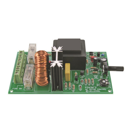
- Page 1 UNIVERSAL AC MOTOR CONTROL K2636 ILLUSTRATED ASSEMBLY MANUAL H2636IP-1...
- Page 2 Features & Specifications This kit is especially designed to control the speed of drills or any other AC-motors with carbon brushes. Contrary to the usual dimmers, there isn't a phase cut every 1/2 period but only once per period. The moment of cutting determines the speed which can be adjusted from 5 to about 95 %.
- Page 3 Assembly hints 1. Assembly (Skipping this can lead to troubles ! ) Ok, so we have your attention. These hints will help you to make this project successful. Read them carefully. 1.1 Make sure you have the right tools: A good quality soldering iron (25-40W) with a small tip. ...
- Page 4 REMOVE THEM FROM THE TAPE ONE AT A TIME ! DO NOT BLINDLY FOLLOW THE ORDER OF THE COMPONENTS ONTO THE TAPE. ALWAYS CHECK THEIR VALUE ON THE PARTS LIST!
- Page 5 Construction 1. Jumper SK4 3. Resistors 4. Metal film resistors Mount jumper according to the main voltage : R... R... R9 : 100 (1 - 0 - 1 - B - 9) R10 : 120 (1 - 2 - 1 - B - 9) ...
- Page 6 Construction 10. Terminal blocks. 7. Transistors. 13. LED T1 : BC547B VAC : 2p LD1 : 3mm RED T2 : BC547B LOAD : 2p T3 : BC547B MAINS : 2p LD... T4 : BC517 CATHODE 8.
- Page 7 Construction 16. Triac. TR1 : BT137F-600 10mm M3 BOLT 3 BOLT LOCK WASHER Place the heatsink and the triac on the PCB. Fix the two components with a M3 bolt and nut. Now, the triac may be soldered.
- Page 8 Test & connection 17. Test & connection ATTENTION: A PART OF THE CIRCUIT IS ALWAYS UNDER MAIN 110 - 240VAC VOLTAGE. TAKE ALL POSSIBLE PRECAUTIONS, SO THAT NO-ONE CAN TOUCH ANY PART. FOR YOUR OWN SECURITY AS FOR THE USERS' SECURITY. MOUNT THIS KIT PREFERABLY IN AN ISOLATING HOUSING.
- Page 9 Test & connection Turn RV1 completely to the left (minimal position) and RV2 completely to the right. Switch the power on. BE CAREFUL: a large part of the circuit is under mains power, do not touch it! ...
- Page 11 Diagram Schematic diagram...
- Page 12 VELLEMAN NV Legen Heirweg 33, B-9890 GAVERE Belgium (Europe) Modifications and typographical errors reserved © Velleman nv., Legen Heirweg 33 - 9890 Gavere (Belgium). H2636IP’1 - 2014 (rev.5) 5 4 1 0 3 2 9 3 1 1 4 1 4...
Need help?
Do you have a question about the K2636 and is the answer not in the manual?
Questions and answers