
Related Manuals for Triner Scale TI-500

Summary of Contents for Triner Scale TI-500
- Page 1 TI-500 / TI-500E Digital Indicator Setup / Operation Manual Revision 2.4 June 8, 2006...
- Page 2 2001 Triner Scale & Mfg. Co., Inc Contents subject to change without notice. Triner Scale & Mfg. Co., Inc 8411 Hacks Cross Road Olive Branch, MS 38654-4010 (662) 890-2385 (800) 238-0152 Fax (662) 890-2386 info@trinerscale.com www.trinerscale.com...
- Page 3 NOTE This equipment has been tested and found to comply with the limits for a Class A digital device, pursuant to Part 15 of the FCC Rules. These limits are designed to provide reasonable protec- tion against harmful interference when the equipment is operated in a commercial environment. This equipment generates, uses and can radiate radio frequency energy and, if not installed and used in accordance with the instructions manual, may cause harmful interference to radio com- munications.
-
Page 4: Table Of Contents
TABLE OF CONTENTS Page Chapter 1: Introduction To The TI-500/500E Indicator ..............1-1 Chapter 2: Installation ........................2-1 ABS Enclosure (TI-500/500E)..................2-1 2.1.1 Connecting the weigh platform................. 2-1 2.1.2 Connecting the serial printer, remote display or computer ......2-2 2.1.3 Connecting the power supply................ - Page 5 C hapter 6: Calibration ........................6-1 Calibration Overview ..................... 6-1 Zero Calibration (F16) ....................6-1 Span Calibration (F17) ....................6-1 View Calibration Values (F18)..................6-2 Key-in Zero Calibration Value (F19) ................6-2 Key-in Span Calibration Value (F20) ................6-3 C hapter 7: Operation........................
- Page 6 Pin Assignments for the Load Cell Port .................. 2-1 Pin Assignments for the DSUB9 serial port connector ............2-2 TI-500/500E Main Circuit Board Overview ................2-2 Connection Assignments for the Load Cell Terminal (J8) ............2-3 Connection Assignments for the serial communication Terminal........... 2-3 Setup Menu Key Assignments....................
-
Page 7: Ti-500 Front Panel
4-350Ω load cells. All setup parameters may be entered via the front panel keys, including calibration. If your Model TI-500/500E Digital Indicator is part of a complete floor scale or has been installed for you, you may skip to Chapter 7 for operating instructions. Prior to using the indicator, please read this chapter carefully and completely. -
Page 8: Chapter 2: Installation
DC Jack RS 232 Connector Figure 2-1: TI-500/500E ABS Enclosure Rear Panel 2.1.1 CONNECTING THE WEIGH PLATFORM The indicators mounted in an ABS enclosure ship with a 15 ft shielded load cell cable for connection to weigh platform’s load cell(s) or junction box. -
Page 9: Connecting The Serial Printer, Remote Display Or Computer
2.1.2 CONNECTING THE SERIAL PRINTER, REMOTE DISPLAY OR COMPUTER The TI-500/500E indicator comes standard with one full duplex RS-232 serial port, designed for connection to either a PC or a serial printer. The same port may be also used as a simplex, RS-232 port designed for connection to a remote display. -
Page 10: Connecting The Weigh Platform
2.2.2 CONNECTING THE SERIAL PRINTER, REMOTE DISPLAY OR COMPUTER The TI-500/500E indicator comes standard with one full duplex RS-232 serial port, designed for connection to either a PC or a serial printer. The same port may be also used as a simplex, RS-232 port designed for connection to a remote display. -
Page 11: Chapter 3: Configuration
CHAPTER 3: CONFIGURATION CONFIGURATION OVERVIEW The indicator contains two main setup menus: The Setup (“F”) menu which configures the indicator to your weigh platform and the User (“A”) menu which configures the serial communication port and enables some user options. The Setup and User menus consist of several menu selections, each with its own sub-menu of choices. -
Page 12: Notes On The Setup Menu
Figure 3-1: Setup Menu Key Assignments Grads Span Gn. Zero Band Zero Range Mot. Band Dig. Filter Ovld. Limit Calib. Unit 0.5d 1d 1d 3d 5d 10d 0d 2% 1d 9d 1 2 4 8 100% 1.9% lb kg 25 50 75 100 150 200 500 1000 1500 2000 2500 3000 4000 5000 6000 8000 10000 12000 20000 30000 40000 50000 Dsp. -
Page 13: Exiting The Setup Menu - Stainless Steel Enclosure
3.2.6 EXITING THE SETUP MENU – STAINLESS STEEL ENCLOSURE 1. Power off the indicator by unplugging the power source. 2. Position the shunt block as shown at right. Note: On certain models, the shunt block position will be exactly the opposite. 3. -
Page 14: Notes On The User Menu
Figure 3-3: User Menu Key Assignments Baud Rate Data Bits, Parity Transmission Mode Display Check Enable lb/kg Key Press ZERO 8n 7O 7E key to begin 1200 2400 4800 9600 Serial Port Mode ID No. Entry No. of Line Feeds ID No. -
Page 15: Chapter 4: Setup Menu Descriptions And Procedures
CHAPTER 4: SETUP MENU DESCRIPTIONS AND PROCEDURES SETUP MENU DESCRIPTIONS This section provides more detailed descriptions of the selections found in the Setup Menu Chart. Factory-set defaults are shown in bold with a checkmark (√). Table 4-1 shows the selections that are not allowed for “Legal-for-Trade” applications: NAME/CODE DESCRIPTION CODE/VALUE... - Page 16 NAME/CODE DESCRIPTION CODE/VALUE Determines the desired weight increments. Value should be consis- 1√ tent with legal requirements. Display Divisions Determines location of the decimal point. 0√ Decimal Pt. 0.00 0.000 0.0000 Places indicator into the zero calibration routine. Scrolling down with Press ZERO key Zero Calibra- the ZERO key one level begins the procedure.
-
Page 17: Chapter 5: User Menu Descriptions And Procedures
CHAPTER 5: USER MENU DESCRIPTIONS AND PROCEDURES USER MENU DESCRIPTIONS This section provides more detailed descriptions of the selections found in the User Menu Chart. Factory-set defaults are shown in bold with a checkmark (√). NAME/CODE DESCRIPTION CODE/VALUE Selects the baud rate for data transmission through the serial port. 1200 2400√... -
Page 18: User Menu Procedures
USER MENU PROCEDURES This section provides instructions for all of the User Menu procedures. 5.2.1 ID Number Entry (A8) While in the User Menu mode, scroll to "A 8", then scroll down once using the ZERO key to enter the ID Number menu. The display will momentarily show "ID NO", followed by a value with one flashing digit. -
Page 19: Chapter 6: Calibration
CHAPTER 6: CALIBRATION CALIBRATION OVERVIEW The indicator is calibrated by following the procedures embedded in F16 (Zero) and F17 (Span) of the Setup Menu. Each procedure enters a value into the indicator's non-volatile memory - F16 the zero value (deadweight) and F17 the span value (test weight). The minimum test weight that can be used is 1% of full-scale capacity. -
Page 20: View Calibration Values (F18)
4. After setting the exact value, press the NET/GROSS key to save the value. 5. If the calibration was successful, the display will show "EndC1" momentarily, then revert back up to F17. At this time it is suggested that the calibration values be recorded for future use (see Section 6.4). -
Page 21: Key-In Span Calibration Value (F20)
KEY-IN SPAN CALIBRATION VALUE (F20) Note: This procedure is intended for emergency use only in the case of non-volatile memory loss. A valid span calibration value, obtained from a successful F17 calibration procedure, must be used. 1. While in the Setup mode, scroll to "F 20", then scroll down once using the ZERO key. 2. -
Page 22: Chapter 7: Operation
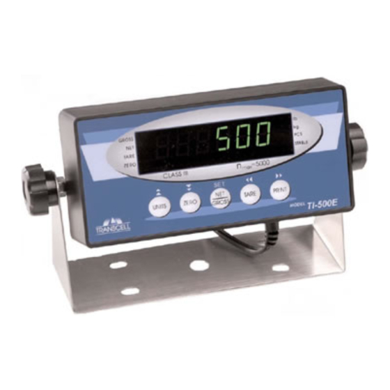
CHAPTER 7: OPERATION 7 .1 DISPLAY The Model TI-500 indicator utilizes a 5-1/2 digit LCD (Liquid Crystal Display) to display the weight and system information while the Model TI-500E indicator utilizes a 6-digit LED (Light Emitting Di- ode) display. Typically, LCD’s are used for outdoor applications while LED’s are used indoors where brightness is needed. -
Page 23: Keyboard
Indicates the unit of the displayed weight. STABLE This light is on whenever the scale is stable. TABLE 7-1: TI-500/500E Annunciator Definitions 7 .2 KEYBOARD The keyboard is composed of five function keys. Refer to Figure 7-3 for the overall layout and key locations. -
Page 24: General Scale Operation
7.3 GENERAL SCALE OPERATION 7.3.1 WEIGHING AN ITEM Select the desired weighing unit by pressing the lb/kg key until that unit is indicated on the display. 2. If necessary, press the ZERO key to obtain a weight reading of zero. 3. -
Page 25: Chapter 8: Legal For Trade Sealing
CHAPTER 8: LEGAL FOR TRADE SEALING ABS ENCLOSURE The TI-500/500E indicator in the ABS enclosure can be sealed for commercial (Legal for rade) applications as follows. 1. Power off the indicator by unplugging the power source. 2. On the back of the indicator, locate the Setup/Calibration Slide Switch Cover Plate (see illustration below). -
Page 26: Appendix A: Specifications
Net, Gross, Stable, Tare, lb, kg, Zero Keyboard 5-key flat membrane panel POWER AC Adapter 12 VDC @ 500mA DC Power Consumption - TI-500 80mA + 30mA/350Ω Load Cell DC Power Consumption - TI-500E 200mA + 30mA/350Ω Load Cell ENVIRONMENTAL Operating Temperature –10°... -
Page 27: Appendix B: Serial Port Information
APPENDIX B: SERIAL PORT INFORMATION SERIAL PORT MODES B.1.1 FULL DUPLEX MODE The Full Duplex Mode provides a Demand serial transmission mode and is selected by setting A3 to “d” and A6 to “0”. The Demand mode allows control from a host device, usually a PC, and can be activated by pressing the PRINT key on the indicator’s front panel. -
Page 28: Recognized Host Commands
B.1.1.1 RECOGNIZED HOST COMMANDS “P” - This command is sent to the indicator to print the indicated display. The indicator will not respond if the scale is in motion, positive overload or negative overload. “Z” - This command is sent to the indicator to zero the scale. The indicator will not respond if the scale is in motion, positive overload or negative overload. -
Page 29: Simplex Mode
B.1.3 SIMPLEX MODE The Simplex Mode provides a continuous serial transmission mode and is selected by setting A3 to “C” and A6 to “0”. The Continuous mode is used to interface to computers, scoreboards, and other remote devices requiring constant data updating. The transmission occurs at the end of each display update. -
Page 30: Appendix C: Determining Proper Span Gain (F2
APPENDIX C: DETERMINING PROPER SPAN GAIN (F2) SPAN GAIN OVERVIEW The Span Gain parameter found in F2 of the Setup Menu is directly related to the ADC (Analog to Digital Converter) integration time. This means that the lower the setting, the higher the number of measurements per second. - Page 31 # of External Full Scale Input Range (mV/V) Grads 1,000 1,500 2,000 2,500 3,000 4,000 5,000 – 6,000 – 8,000 – 10,000 – – 12,000 – – 15,000 – – – 20,000 – – – – 30,000 – – – –...
-
Page 32: Appendix D: Displayed Error Codes
APPENDIX D: DISPLAYED ERROR CODES CODE MODE MEANING / POSSIBLE SOLUTION Normal Operating Gross Overload. A weight greater than the rated capacity has been Mode applied to the scale. Remove the weight from the platter or try re- calibrating the scale. Otherwise, check for a bad load cell connection or possible load cell damage due to overloading. - Page 33 If you are authorized by Triner Scale to ship the product to Triner Scale for repair, it is your responsibility to securely package the product in its original container or an equivalent and provide proof of the date of original purchase. You will be responsible for shipping costs to Triner Scale repair facility.
Need help?
Do you have a question about the TI-500 and is the answer not in the manual?
Questions and answers