
Related Manuals for Acer Aspire 1640


Summary of Contents for Acer Aspire 1640
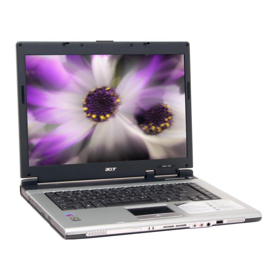
- Page 1 Aspire 1640 Series Service Guide Service guide files and updates are available on the ACER/CSD web; for more information, please refer to http://csd.acer.com.tw PRINTED IN TAIWAN...
-
Page 2: Revision History
Revision History Please refer to the table below for the updates made on Aspire 1640 service guide. Date 200512/27 Chapter 1 2006/02/15 Chapter 3 Chapter Revise memory specification to 533MHz on page 20. Revise disassembling SOP. Updates... - Page 3 Copyright Copyright © 2005 by Acer Incorporated. All rights reserved. No part of this publication may be reproduced, transmitted, transcribed, stored in a retrieval system, or translated into any language or computer language, in any form or by any means, electronic, mechanical, magnetic, optical, chemical, manual or otherwise, without the prior written permission of Acer Incorporated.
- Page 4 Conventions The following conventions are used in this manual: SCREEN MESSAGES NOTE WARNING CAUTION IMPORTANT Denotes actual messages that appear on screen. Gives bits and pieces of additional information related to the current topic. Alerts you to any damage that might result from doing or not doing specific actions.
- Page 5 DIFFERENT part number code to those given in the FRU list of this printed Service Guide. You MUST use the list provided by your regional Acer office to order FRU parts for repair and service of customer machines.
-
Page 7: System Introduction
Simultaneous LCD and CRT display with LCD panel resolution at 70 Hz Communication Modem: 56K ITU V.92 modem with PTT approval; Wake-on-Ring ready LAN: 10/100 Mbps Fast Ethernet; Wake-on-LAN ready Wireless LAN (optional): integrated miniPCI Acer InviLink solution Acer SignalUP wireless technology support Wireless PAN (optional): integrated Bluetooth... - Page 8 Built-in microphone Input devices 88-/89-key Acer FineTouch Touchpad with 4-way integrated scroll button Four easy-launch buttons Two front-panel buttons: wireless LED-button and Bluetooth I/O interface Three USB 2.0 ports Ethernet (RJ-45) port Modem (RJ-11) port External display (VGA) port Microphone...
- Page 9 System Block Diagram Chapter 1...
-
Page 10: Board Layout
Board Layout Top View Aspire 1640... -
Page 11: Bottom View
Bottom View Lid Switch Launch Board Connector Keyboard Connector Touchpad Board Connector Clock Generator MDC Connector CN13 Power Jack CN14 Battery Connector CN17 RJ45 & RJ11 Connector North Bridge Chapter 1 LCD Connector Modem Connector Bluetooth Module Connector Internal Microphone Connector PCMCIA Connector CN11 Internal Speaker Connector... - Page 12 LED1 Power LED Fan Connector CN21 USB Connector EC PC97551 (Power and I/O Connector) CN18 Memory Socket 1 CN19 Memory Socket 2 CN24 PCMCIA Connector CN27 USB Connector CN29 Microphone Jack WLAN Button LED2 Charger LED Audio Codec Aspire 1640...
-
Page 13: Front View
Panel This is a brief introduction to the I/O ports, the features and the indicators. Front view Display screen Microphone Keyboard Palmrest Click buttons (Left and right) Touchpad Status indicators Launch keys Power button Chapter 1 Item Also called LCD (Liquid Crystal Display), displays computer output. -
Page 14: Closed Front View
(optional). Accepts audio line-in devices (e.g., audio CD player, stereo walkman). Accepts inputs from external microphones. Connects to audio line-out devices (e.g., speakers, headphones). Connects to Universal Serial Bus (USB) 2.0 devices (e.g., USB mouse, UsB camera). Aspire 1640... -
Page 15: Right View
Icon Optical drive LED indicator Emergency eject hole Optical drive eject button Right view Icon Rear view Chapter 1 Item/ Port Internal optical drive; accepts CDs or DVDs depending on the optical drive type. Lights up when the optical drive is active. Ejects the optical drive tray when the computer is turned off. - Page 16 Unlatches the battery to remove the battery pack. Houses the computer’s battery pack. Locks the battery in place. Helps keep the computer cool. Note: Do not cover or obstruct the opening of the fan. House the computer’s main memory. Description Description Aspire 1640...
- Page 17 Indicators The computer has three easy-to-read status icons on the upper-right above the keyboard, and four on the front panel. Icon Function Icon NOTE: 1. Charging: the light shows amber when the battery is charging. NOTE: 2. Fully charged: light shows green when in AC mode. Chapter 1 Description Function...
-
Page 18: Launch Keys
“ to run the Acer eManager. The mail and Web buttons are pre-set ot email and internet programs, Fn-F3 eManager" on page 23 but can be reset by users. To set the Web browser, mail and programmable keys, run the Acer Launch Manager. Fn>... -
Page 19: Using The Keyboard
Using the keyboard The keyboard has full-sized keys and an embedded keypad, separate cursor keys, two Windows keys and twelve function keys. Lock keys and embedded numeric keypad The keyboard has three lock keys which you can toggle on and off. Lock key Caps Lock Num Lock (Fn-F11) -
Page 20: Windows Keys
+ <M> (Minimizes all windows) <shift> +< M> (Undoes the minimize all windows) This key has the same effect as clicking the right mouse button; it opens the application’s context menu. Num lock off Type the letters in a normal manner. Description Aspire 1640... -
Page 21: Special Keys
To type: Chapter 1 Function Hotkey help Displays a list of the hotkeys and their functions. Acer eSetting Launches Acer eSetting in Acer eManager. Acer Power Launches Power Management options. Management Sleep Puts the computer in Sleep mode. - Page 22 Either directly press the <Euro> key at the bottom-right of the keyboard (for Chinese keyboard), or hold <Shift> and then press the <4> key at the upper-center of the keyboard.symbol at the upper-center of the keyboard (for European keyboard, you can use both method). NOTE: This function varies according to the language settings. Aspire 1640...
-
Page 23: Touchpad Basics
Touchpad The built-in touchpad is a pointing device that senses movement on its surface. This means the cursor responds as you move your finger on the surface of the touchpad. The central location on the palmrest provides optimum comfort and suuport. Touchpad basics The following items teach you how to use the touchpad: * Move your finger across the touchpad (2) to move the cursor. - Page 24 Tap once. Tap twice (at the same speed as double-clicking a mouse button); hold finger to the touchpad on the second tap and drag the cursor. Click once. Center button (3) Click and hold to move up/down/left/ right. Aspire 1640...
-
Page 25: Hardware Specifications And Configurations
Hardware Specifications and Configurations System Board Major Chip Item System core logic Memory controller Audio controller PCMCIA controller for socket Video controller Power and Keyboard controller Wireless controller (mini PCI) Processor Item CPU type CPU package CPU core voltage CPU I/O voltage BIOS Item BIOS vendor... - Page 26 Slot 2 256MB 512MB 1024MB 256MB 512MB 1024MB 256MB 512MB 1024MB 256MB 512MB 1024MB Specification RealTek 8100CL 10/100 RJ45 Right side Total Memory 256MB 512MB 1024MB 256MB 512MB 768MB 1280MB 512MB 768MB 1024MB 1536MB 1024MB 1280MB 1536MB 2048MB (2G) Aspire 1640...
- Page 27 Modem Interface Item Chipset Fax modem data baud rate (bps) Data modem data baud rate (bps) Supports modem protocol Modem connector type Modem connector location Wireless Module 802.11b/g (optional device) Item Chipset Data throughput Protocol Interface Floppy Disk Drive Interface Item Vendor &...
- Page 28 5/9/10/18 DVD-Single/Dual (PTP, OTP) 3.9/4.7G DVD-R (Read Only) 4.7GDVD+R (Read Only) DVD±RW (Read only) 80mm DVD 4200RPM 8MBytes ATA/ATAPI-6 100 MB/Sec 5 +/- 5% Remark CAV 24X CAV 24X P-CAV 24X/20X/16X ; CLV 10X/8X/4X CLV 10X/4X P-CAV 24X/16X All angles Aspire 1640...
- Page 29 Combo Drive Interface Item Format compatibility Loading mechanism Power Requirement Input Voltage DVD-RW Interface Item Vendor & model name Performance Specification Transfer rate (KB/sec) (1) Read DVD-ROM DVD-R CD-ROM (2) Write CD-R CD-RW HS-RW US-RW (3) ATAPI Interface PIO mode DMA mode Ultra DMA mode Buffer Memory...
- Page 30 DMA channel 0 DMA channel 1 IRQ10, IRQ11 ® built-in Intel 915GM up to 128MB for Aspire 3000/5000 up to 64MB for Aspire 3500 Core / 2.5V, 1.5V, 4X AGP (Accelerated Graphic Port) Bus 1600X1200 (UXGA) 2048X1536@60HZ Specification Specification Aspire 1640...
- Page 31 Video Resolutions Mode Monitor Resolution 2048x1536 Resolution, colors and maximum refersh rate (Hz) in 256, 65K or 16.7M colors. NOTE: 16:9 aspect ratio monitors are supported on 1920x1080 and 848x480 on Windows(R)XP, Windows(R) 2000 and Windows(R)ME. The complete list of resolutions depends on the driver version and operating system.
- Page 32 Normally white Hard coating (2H) glare+ Anti reflective treatment of the front polarizer not show 30(rise+falling) not show Total 5.26 @LCM circuit 1.12, backlight input 4.14 344(W)x222(H)x6.5(D) 262K colours 60/60 40/50 0 to 50 -20 to -60 Specification Aspire 1640...
- Page 33 AC Adapter Item Frequency variation range (Hz) Input voltage range (Vrms) Inrush current Efficiency Output Ratings (CV mode) DC output voltage Noise + Ripple Load Output Ratings (CC mode) DC output voltage Constant current mode Dynamic Output Characteristics Turn-on delay time Hold up time Over Voltage Protection (OVP) Short circuit protection...
-
Page 34: Environmental Requirements
Type II PC Card slot DC-in jack for AC adaptor LED indicator for keyboard hot key: Caps Lock, Scroll Lock, NUmber lock LED indicator for function indicator: System power-on, HDD/ODD, Wireless on/off, Arcade LED mode, DC-in, Battery/Charging indicator Power Management Aspire 1640... - Page 35 Mechanical Specification Item Specification Switch Power Chapter 1...
-
Page 36: System Utilities
System BIOS Ver V1.0 VGA BIOS Ver KBC Ver xxxxxxxxxxxxxxxxxxxxxx Serial Number Asset Tag Number Produce Name Aspire 3000 Manufacturer Name: Acer xxxxxxxxxxxxxxxxxxxxxxxxxxxxxxxx UUID: Help Select Item ↑ ↓ ← → Exit Select Menu Chapter 2 during POST (when “Press <F2> to enter Setup” message is prompted... -
Page 37: Navigating The Bios Utility
Navigating the BIOS Utility There are six menu options: Info., Main, System Devices, Security, Boot, and Exit. Follow these instructions: To choose a menu, use the cursor left/right keys (zx). To choose a parameter, use the cursor up/down keys ( wy). To change the value of a parameter, press por q. - Page 38 V1.0 VGA BIOS Ver KBC Ver xxxxxxxxxxxxxxxxxxxxxx Serial Number Asset Tag Number Produce Name Aspire 3000 Manufacturer Name: Acer xxxxxxxxxxxxxxxxxxxxxxxxxxxxxxxx UUID: Help Select Item ↑ ↓ ← → Exit Select Menu NOTE: The system information is subject to different models.
- Page 39 Main The Main screen displays a summary of your computer hardware information, and also includes basic setup parameters. It allows the user to specify standard IBM PC AT system parameters. Info. Main System Time: System Date: System Memory: 640 KB Extended Memory: 446MB Video Memory...
- Page 40 The table below describes the parameters in this screen. Settings in boldface are the default and suggested parameter settings. Parameter System Time Sets the system time. The hours are displayed with 24-hour format. System Date Sets the system date. System Memory This field reports the memory size of the system.
- Page 41 Security The Security screen contains parameters that help safeguard and protect your computer from unauthorized use. Info. Main Supervisor Password Is: User Password Is: Primary HardDisk Security: HDD Master ID: Set Supervisor Password Set User Passord Set HDD Password Password on Boot Help Select Item ↑...
- Page 42 The table below describes the parameters in this screen. Settings in boldface are the default and suggested parameter settings. Parameter User Password is Supervisor Password is Set User Password Set Supervisor Password Primary Harddisk Security Password on Boot NOTE: When you are prompted to enter a password, you have three tries before the system halts. Don’t forget your password.
- Page 43 Press e. After setting the password, the computer sets the User Password parameter to “Set”. If desired, you can opt to enable the Password on boot parameter. When you are done, press u to save the changes and exit the BIOS Setup Utility. Removing a Password Follow these steps: Use the w and y keys to highlight the Set Supervisor Password parameter and press the e key.
- Page 44 If the verification is OK, the screen will display as following. The password setting is complete after the user presses u. If the current password entered does not match the actual current password, the screen will show you the Setup Warning. If the new password and confirm new password strings do not match, the screen will display the following message.
- Page 45 Boot This menu allows the user to decide the order of boot devices to load the operating system. Bootable devices includes the distette drive in module bay, the onboard hard disk drive and the CD-ROM in module bay. Info. Main CD-ROM/DVD Drive Floppy Devices +Hard Drive...
-
Page 46: Exit
Exit The Exit screen contains parameters that help safeguard and protect your computer from unauthorized use. Info. Main Exit Saving Changes Exit Dicarding Changes Load Setup Defaults Discard Changes Save Changes Help ↑ ↓ Select Item ← → Exit Select Menu The table below describes the parameters in this screen. -
Page 47: Bios Flash Utility
BIOS Flash Utility The BIOS flash memory update is required for the following conditions: New versions of system programs New features or options Restore a BIOS when it becomes corrupted. Use the Phlash utility to update the system BIOS flash ROM. NOTE: If you do not have a crisis recovery diskette at hand, then you should create a Crisis Recovery Diskette before you use the Phlash utility. - Page 48 Chapter 2...
- Page 49 Chapter 2...
-
Page 50: Machine Disassembly And Replacement
Machine Disassembly and Replacement This chapter contains step-by-step procedures on how to disassemble the notebook computer for maintenance and troubleshooting. To disassemble the computer, you need the following tools: Wrist grounding strap and conductive mat for preventing electrostatic discharge Flat-bladed screw driver Phillips screw driver Tweezers Plastic Flat-bladed screw driver... -
Page 51: General Information
General Information Before You Begin Before proceeding with the disassembly procedure, make sure that you do the following: Turn off the power to the system and all peripherals. Unplug the AC adapter and all power and signal cables from the system NOTE: Aspire 9100 series product uses mylar or tape to fasten the FFC/FPC/connectors/cable, you may need to tear the tape or mylar before you disconnect different FFC/FPC/connectors. -
Page 52: Disassembly Procedure Flowchart
Disassembly Procedure Flowchart The flowchart on the succeeding page gives you a graphic representation on the entire disassembly sequence and instructs you on the components that need to be removed during servicing. For example, if you want to remove the main board, you must first remove the keyboard, then disassemble the inside assembly frame in that order. - Page 53 Antenna set Screw List Item Description SCREW F040 9 5.0X5.0 9.5X(IO) R00 SCREW M2.0X0.4P+3FP ZK(NL) SCREW M2.5 K 5/2 X0.85 4 ZK(NL) SCREW M2.5X0.45+10K NIL SCREW M2.5X0.45+8K ZBL SCREW M2.5X0.45P+3F NI SCREW M3.0X0.8P+3K NL LCD Module LCD Bezel *6 hinges *2 brackets LCD Cover Assembly...
-
Page 54: Removing The Battery Pack
Removing the Battery Pack Unlock the battery lock. Slide the battery latch as shown. Then remove the battery pack. Chapter 3... - Page 55 Removing the HDD Module/the Memory and the Wireless LAN Card/ the Thermal Module and the CPU/ODD Module and LCD Module Removing the HDD Module Remove the two screws holding the HDD cover. Remove the HDD cover. Remove the screw fastening the HDD module to the notebook. Then detach the HDD module from the notebook.
-
Page 56: Removing The Thermal Module And Cpu
Removing the Thermal Module and CPU Remove the three screws holding the thermal door Detach the thermal door. Disconnect the fan cable from the main board. Remove the three screws fastening the thermal module. Disconnect the fan cable. NOTE: When you remove the screws fastening the thermal module, please follow the number order 3, 2, 1 on the thermal module. -
Page 57: Removing The Odd Module
Removing the ODD Module Remove the three screws holding the middle cover. Detach the middle cover carefully. Then remove the two screws fastening the keyboard. Turn over the keyboard as shown. Disconnect the keyboard cable from the main board then remove the keyboard. Remove the screw that fastens the ODD module. - Page 58 Remove the two screws that secure the keyboard as shown. Turn over the keyboard as shown and disconnect the keyboard cable then remove the keyboard. Pull out the antenna set with a tweezers then take out the antenna set from the main unit. Disconnect the LCD coaxial cable.
-
Page 59: Disassembling The Main Unit
Disassembling the Main Unit Separate the Main Unit Into the Upper and the Lower Case Assembly Remove the two screws holding the switch board. Remove the switch board. Disconnect the touchpad FFC from the main board. Disconnect the bluetooth cable. Remove the five screws that secure the upper case. -
Page 60: Disassembling The Lower Case Assembly
Remove the three screws that secure the touchpad board. Remove the touchpad board from the upper case. Disconnect the touchpad board to touchpad FFC. Remove the touchpad board to touchpad FFC from the uppwer case assembly. Remove the four screws holding the touchpad bracket. Detach the touchpad bracket from the upper case assembly. - Page 61 Detach the MDC cable from the main board. Remove the two screws holding the modem board then disconnect the modem board from the main board. Disconnect the speaker cable from the main board. Remove the screw that secure the main board. Remove the two screw nuts as shown.
- Page 62 IMPORTANT:When assembling/disassembling the main board, whenever there is a mylar on the main board (see the highlighted with red below; the mylar is sami-transparent, film-like stuff ), it should be transferred “if necessary” to the replacement main board. Because the main board mylar should be stuck to the main board to prevent the antenna cable and the main board components short circuit.
-
Page 63: Disassembling The Lcd Module
Disassembling the LCD Module Remove the four screw caps as shown. Remove the four screws holding the LCD bezel. Then detach the LCD bezel from the LCD module. Disconnect the inverter board then remove it. Remove the three screws holding the right hinge. Then remove the three screws that secure the left hinge. - Page 64 13. Remove the left bracket as the picture shows. 14. Tear off the tape fastening the LCD cable. 15. Tear off the the LCD cable fastening the LCD cable, then remove it.. Chapter 3...
-
Page 65: Disassembling The External Modules
Disassembling the External Modules Disassembling the HDD Module Remove the two screws holding the HDD bracket on one side. Remove another two screws holding the HDD bracket on the other side. Then take the hard disc drive out from the HDD bracket. Disassembling the Optical Drive Module Remove the four screws as the picture shows. -
Page 66: Table Of Contents
Troubleshooting Use the following procedure as a guide for computer problems. NOTE: The diagnostic tests are intended to test only Acer products. Non-Acer products, prototype cards, or modified options can give false errors and invalid system responses. Obtain the failing symptoms in as much detail as possible. -
Page 67: System Check Procedures
System Check Procedures External Diskette Drive Check Do the following to isolate the problem to a controller, driver, or diskette. A write-enabled, diagnostic diskette is required. NOTE: Make sure that the diskette does not have more than one label attached to it. Multiple labels can cause damage to the drive or cause the drive to fail. -
Page 68: Memory Check
If any of these devices do not work, reconnect the cable connector and repeat the failing operation. Memory check Memory errors might stop system operations, show error messages on the screen, or hang the system. Boot from the diagnostics diskette and start the doagmpstotics program (please refer to main board. Go to the diagnostic memory in the test items. - Page 69 Check the Power Adapter Unplug the power adapter cable from the computer and measure the output voltage at the plug of the power adapter cable. See the following figure If the voltage is not correct, replace the power adapter. If the voltage is within the range, do the following: Replace the System board.
-
Page 70: Touchpad Check
Check the Battery Pack To check the battery pack, do the following: From Software: Check out the Power Management in control Panel In Power Meter, confirm that if the parameters shown in the screen for Current Power Source and Total Battery Power Remaining are correct. -
Page 71: Power-On Self-Test (Post) Error Message
Power-On Self-Test (POST) Error Message The POST error message index lists the error message and their possible causes. The most likely cause is listed first. NOTE: Perform the FRU replacement or actions in the sequence shown in FRU/Action column, if the FRU replacement does not solve the problem, put the original part back in the computer. -
Page 72: Error Message List
Index of Error Messages Error Code List Error Codes <No error code> <No error code> Error Message List Error Messages Failure Fixed Disk Stuck Key Keyboard error Keyboard Controller Failed Keyboard locked - Unlock key switch Monitor type does not match CMOS - Run Setup Run “Load Default Settings” in BIOS Setup Utility. Shadow RAM Failed at offset: nnnn System RAM Failed at offset: nnnn Extended RAM Failed at offset: nnnn... - Page 73 Error Message List Error Messages Real time clock error Previous boot incomplete - Default configuration used Memory size found by POST differed from CMOS Diskette drive A error Incorrect Drive A type - run SETUP System cache error - Cache disabled CPU ID: DMA Test Failed Software NMI Failed...
- Page 74 Error Message List No beep Error Messages No beep, power-on indicator turns off and LCD is blank. No beep, power-on indicator turns on and LCD is blank. No beep, power-on indicator turns on and LCD is blank. But you can see POST on an external CRT.
-
Page 75: Phoenix Bios Beep Codes
Phoenix BIOS Beep Codes Code Beeps Verify Real Mode Disable Non-Maskable Interrupt (NMI) Get CPU type Initialize system hardware Initialize chipset with initial POST values Set IN POST flag Initialize CPU registers Enable CPU cache Initialize caches to initial POST values Initialize I/O component Initialize the local bus IDE Initialize Power Management... - Page 76 Code Chapter 4 Beeps 2-1-2-3 Check ROM copyright notice Check video configuration against CMOS Initialize PCI bus and devices Initialize all video adapters in system QuietBoot start (optional) Shadow video BIOS ROM Display BIOS copyright notice Display CPU type and speed Initialize EISA board Test keyboard Set key click if enabled...
- Page 77 Code Beeps Initialize floppy controller Determine number of ATA drives (optional) Initialize hard-disk controllers Initialize local-bus hard-disk controllers Jump to UserPatch2 Build MPTABLE for multi-processor boards Install CD ROM for boot Clear huge ES segment register Fixup Multi Processor table Search for option ROMs.
- Page 78 Code Code Chapter 4 Beeps Unknown interrupt Beeps Initialize the chipset Initialize the bridge Initialize the CPU Initialize the system timer Initialize system I/O Check force recovery boot Checksum BIOS ROM Go to BIOS Set Huge Segment Initialize Multi Processor Initialize OEM special code Initialize PIC and DMA Initialize Memory type...
-
Page 79: Index Of Symptom-To-Fru Error Message
Index of Symptom-to-FRU Error Message LCD-Related Symptoms Symptom / Error LCD backlight doesn't work LCD is too dark LCD brightness cannot be adjusted LCD contrast cannot be adjusted Unreadable LCD screen Missing pels in characters Abnormal screen Wrong color displayed LCD has extra horizontal or vertical lines displayed. - Page 80 Power-Related Symptoms Symptom / Error Battery can’t be charged PCMCIA-Related Symptoms Symptom / Error System cannot detect the PC Card (PCMCIA) PCMCIA slot pin is damaged. Memory-Related Symptoms Symptom / Error Memory count (size) appears different from actual size. Speaker-Related Symptoms Symptom / Error In Windows, multimedia programs, no sound comes from the computer.
- Page 81 Power Management-Related Symptoms Symptom / Error Battery fuel gauge in Windows doesn’t go higher than 90%. System hangs intermittently. Peripheral-Related Symptoms Symptom / Error System configuration does not match the installed devices. External display does not work correctly. USB does not work correctly Print problems.
-
Page 82: Intermittent Problems
Intermittent Problems Intermittent system hang problems can be caused by a variety of reasons that have nothing to do with a hardware defect, such as: cosmic radiation, electrostatic discharge, or software errors. FRU replacement should be considered only when a recurring problem exists. When analyzing an intermittent problem, do the following: Run the advanced diagnostic test for the system board in loop mode at least 10 times. -
Page 83: Undetermined Problems
System Check” on page 68): Power-off the computer. Visually check them for damage. If any problems are found, replace the FRU. Remove or disconnect all of the following devices: Non-Acer devices Printer, mouse, and other external devices Battery pack Hard disk drive... - Page 84 DIFFERENT part number code from those given in the FRU list of this printed Service Guide. You MUST use the local FRU list provided by your regional Acer office to order FRU parts for repair and service of customer machines.
- Page 85 Aspire 1640 Exploded Diagram Aspire 1640 FRU List Adapter Battery ADP 19V 3.42A PA-1650-02QR 90~264V LF ADP 19V 3.42A SLS0335A19A57LF 90~264V EU ADP 19V 3.42A SADP-65KB DBHF 90~264V LF AP.06503.010 AP.06506.002 AP.06501.009 Chapter 6...
- Page 86 Aspire 1640 FRU List Board Cable Chapter 6 BATTERY SANYO LI-ION 4S2P 4.4A 4UR18650F-2-QC140 BATTERY PANASONIC LI-ION 4S2P 4.4A CGR-B/8B5AE BATTERY PANASONIC LI-ION 4S2P 4.4A ROHS BATTERY SIMPPLO PACK LI-ION 4S1P 2.0A BATTERY SANYO PACK LI-ION 4S1P 2.0A BATTERY SONY PACK LI-ION 4S1P 1.96A...
- Page 87 Aspire 1640 FRU List Case/Cover/Bracket Assembly FFC CABLE - TP/B TO MB MODEM CABLE POWER CORD US (3 PIN) POWER CORD PRC (3 PIN) POWER CORD KOERA ( Pin) POWER CORD EU (3 PIN) POWER CORD UK (3 PIN) POWER CORD ITALIAN (3 PIN)
- Page 88 Aspire 1640 FRU List Communication Module CPU/Processor Optical Disk Drive Module Chapter 6 HEATSINK COVER W/O DOCKING 3 IN 1 DUMMY COVER HDD COVER HDD BRACKET WIRELESS LAN ANTENNA AMD MOBILE SEMPRON 2800+ 25WD AMD MOBILE SEMPRON 3000+ 25WD AMD MOBILE TURION 64 ML28...
- Page 89 Aspire 1640 FRU List DVD/CDRW COMBO MODULE 24X PHILIPS SCB5265 LF DVD/CDRW COMBO DRIVE 24X PHILIPS SCB5265 GB LF OPTICAL DEVICE HOLDER-FIX DVD/CDRW BEZEL FOR G BASE DVD/CDRW COMBO MODULE KME UJDA-770 DVD/CDRW COMBO DRIVE 24X KME UJDA-770 OPTICAL DEVICE HOLDER-FIX...
- Page 90 Aspire 1640 FRU List HDD/Hard Disk Drive Chapter 6 DVD DUAL DRIVE PANASONIC UJ- 840BAA2 D. LAYER G BASE OPTICAL DEVICE HOLDER-FIX DVD DUAL BEZEL G BASE DVD DUAL MODULE LITE-ON SOSW-833 DL G BASE DVD DUAL DRIVE LIET-ON SOSW-...
- Page 91 Aspire 1640 FRU List Keyboard 60G WD 2.5 IN. 5400RPM ML40 WD600UE-22HCT0 (ROHS) 80G SEAGATE 2.5 IN. 4200RPM N2.2ST980829A F/W:3.04 80G TOSHIBA 2.5 IN. 4200RPM PLUTO MK8025GAS (ROHS) F/W KA023 80G HGST 2.5 IN. 4200RPM HAKONE-A F/W:A70G 80G WD 2.5 IN. 5400RPM ML40 WD800UE-22HCT0 (ROHS) 100G TOSHIBA 2.5 IN.
- Page 92 Aspire 1640 FRU List LCD Module Chapter 6 AS1680/AS1410 KEYBOARD DARFON Hungaian AS1680/AS1410 KEYBOARD DARFON Norway AS1680/AS1410 KEYBOARD DARFON Danish AS1680/AS1410 KEYBOARD DARFON Turkish AS1680/AS1410 KEYBOARD DARFON Canadian French AS1680/AS1410 KEYBOARD DARFON Japanese AS1680/AS1410 KEYBOARD DARFON Greek AS1680/AS1410 KEYBOARD DARFON Hebrew...
- Page 93 Aspire 1640 FRU List LCD BRACKET W/HINGE 15 IN. - L LCD BRACKET W/HINGE 15 IN. - R LCD PANEL W/LOGO ANTENNA 14/ 15 IN. LCD BEZEL W/RUBBER PAD 15 IN. LCD 15.0 IN. MODULE CMO N150X3- L07 LF LCD 15.0 IN. XGA CMO N150X3-L07...
- Page 94 Aspire 1640 FRU List Chapter 6 LCD PANEL W/LOGO ANTENNA 14/ 15 IN. LCD BEZEL W/RUBBER PAD 15 IN. LCD 15.0 IN. MODULE LPL LP150X07-TLA2 LF LCD 15.0 IN. XGA LPL LP150X07- TLA2 LF LCD INVERTER BOARD LCD CABLE - 15 IN. XGA LCD BRACKET W/HINGE 15 IN.
- Page 95 Aspire 1640 FRU List LCD PANEL W/LOGO ANTENNA 15.4 IN. LCD BEZEL W/RUBBER PAD 15.4 IN. LCD 15.4 IN. MODULE AU B154EW01 V8 LF NON-G LCD 15.4 IN. WXGA AU B154EW01 V8 LF NON-G LCD INVERTER BOARD LCD CABLE - 15.4 IN. WXGA LCD BRACKET W/HINGE 15.4 IN.
- Page 96 Aspire 1640 FRU List Main Board Memory Chapter 6 LCD PANEL W/LOGO W/O ANTENNA 14/15 IN. LCD BEZEL W/RUBBER PAD 15 IN. LCD 15.4 MODULE QDI QD15TL02- 03 LF NON-GLARE W/O WIRELESS LCD 15.4 WXGA QDI QD15TL02-03 LF NON-GLARE LCD INVERTER BOARD LCD CABLE - 15.4 IN.
- Page 97 Aspire 1640 FRU List Speaker Heatsink Miscellaneous Screw MEMORY DDR333 256MB INFINEON HYS64D32020HDL-6-C (.11u) MEMORY DDR333 256MB NANYA NT256D64SH8C0GM-6K MEMORY DDR333 256MB SAMSUNG M470L3224FT0-CB3 MEMORY DDR333 256MB HYNIX HYMD232M646D6-J MEMORY DDR333 512MB INFINEON HYS64D64020HBDL-6-C (.11u) MEMORY DDR333 512MB SAMSUNG M470L6524BT0-CB3...
- Page 98 Chapter 6...
Need help?
Do you have a question about the Aspire 1640 and is the answer not in the manual?
Questions and answers