Table of Contents
Troubleshooting

Related Manuals for jeiko ALLGUARD JKAL370GSM


Summary of Contents for jeiko ALLGUARD JKAL370GSM
- Page 1 Siistema d’allarme anti-intrusione con guida a sintesi vocale doppio combinatore telefonico GSM & PSTN JKAL370GSM Burglar alarm system speech guide Twin dialer GSM & PSTN...
- Page 3 Centrale di Allarme due aree, 32 zone senza fili e 8 zone filari ALLGUARD JKAL370GSM si installa in modo semplice e veloce, senza rompere muri, spostare mobili o sporcare. Nel seguente manuale vengono fornite le indicazioni e consigli per una corretta messa in funzione del sistema, sono necessarie 1 o 2 ore per la completa installazione.
- Page 4 INTRODUZIONE CARATTERISTICHE *Guida vocale per programmazione e operazioni d’uso. *Regolazione volume della guida vocale *Interfaccia utente : LCD display grafico con icone & indicatori stato *Doppio combinatore telefonico PSTN e GSM *2 aree attivabili con relativi inserimenti : Totale o Parziale *32 zone senza filo e 8 zone filari *Programmazione indipendente per ogni zona.
-
Page 5: Funzionamento
INTRODUZIONE FUNZIONAMENTO Tutti i componenti del sistema di allarme ALLGUARD JKAL370GSM sono disegnati e progettati con un alto standard di sicurezza e qualità per fornire una protezione sicura, completa e duratura ; utilizzano il sistema di trasmissione digitale random jumper code di ultima generazione che garantisce la massima sicurezza , immunità... - Page 6 INTRODUZIONE Sicurezza. Durante l'uso di attrezzi da lavoro per l'installazione della centrale di allarme o dei sensori, seguire i consigli dei fabbricanti, (utilizzare strumenti di protezione, tipo, guanti da lavoro, occhiali di sicurezza ove previsti), prima di utilizzare un trapano elettrico o a batterie, assicurasi che le punte per il foro siano del tipo appropriato, (cemento o legno) soprattutto verificare prima di forare che nella posizione da voi accertata non passino cavi elettrici o tubi per l'acqua.
-
Page 7: Sistemi Di Protezione
INTRODUZIONE Il sistema di allarme senza fili ALLGUARD JKAL370GSM ha 2 aree di intervento concatenate (Parziale e Totale).che possono essere attivate a vs. scelta. Le 32 zone (sensori senza filo) e le 8 (sensori filari) possono essere configurati in vari modi. I sensori aggiuntivi... - Page 8 INTRODUZIONE (area perimetrale inserita). PROTEZIONE PARZIALE La centrale di allarme, consente di attivare separatamente le zone (i sensori) registrati e configurati nell'area perimetrale. Pertanto durante le ore notturne attivando le zone perimetrali, potrete così occupare i locali senza che i sensori di movimento posizionati all'interno attivino il sistema d'allarme.
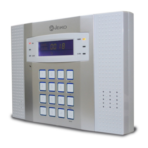
- Page 9 INTRODUZIONE 1.2 Introduzione del pannello di controllo. Led indicatore Rete Led inserimento Led disinserito Led allarme Sirena Tastiera Check/Enter Buzzer e microfono NOTA : Led Indicatore Rete: Acceso in presenza di tensione, spento in assenza di tensione,Lampeggiante con sensori aperti. Led Indicatore Allarme: Rosso lampeggiante allarme in corso.
-
Page 10: Installazione Del Sistema
Installazione & connessioni 2. Installazione & connessioni 2.1 Preparazione del sistema Aprire la confezione e verificare che il prodotto sia completo di tutti gli accessor 2.2 Installazione del sistema Posizionamento e installazione della centrale di allarme Prima di procedere con l'istallazione della centrale di allarme, ė consigliabile osservare i seguenti punti sotto menzionati: * La centrale di controllo va posizionata in un posto sicuro difficilmente accessibile ad eventuali intrusi, ma facilmente... - Page 11 Installazione & connessioni Si raccomanda: Di posizionare la centrale di allarme in prossimità dell'ingresso della porta principale in modo che si possa udire il tono di attivazione e disattivazione del sistema di allarme da parte dell'utilizzatore. *. Di posizionare la centrale di allarme nella zona di ingresso protetto da porta e rilevatore di apertura, oppure da sensore di movimento in modo da proteggere la centrale da qualunque intrusione illegale.
- Page 12 Connessioni 2.3 Connessioni Effettuare i collegamenti come da figura a seguito riportata. Collegareil cavo della linea telefonica ed il telefono nelle prese dedicate Inserire il jack di alimentazione nell’apposita presa ed inserire l’alimentatore nella presa di corrente a muro. Alimentatore Linea telefonica Volume guida vocale...
- Page 13 Connessione sensori fillari 2.5 Connessioni sensori filari 2.5 Connessioni sensori filari DC 12V 1500mA output DC 12V Collegamento N.O Collegamento N.C polo positivo d’uscita Nota: In assenza di rete AC power, la tensione d’uscita al terminale AUX e’ di 9V Linea Telefonica LINE...
- Page 14 Settaggi e funzioni di base 3 Settaggi di base 3.1 Impostazioni di fabbrica Di seguito troverete le impostazioni di fabbrica, è possibile modificarle secondo vs. esigenze.. -Password di sistema: 9876 -Password Utente: 1234 -Tempo di ritardo Entrata / uscita : 10 s econdi -Combinatore GSM : disattivato ( prioritàPSTN)
- Page 15 Settaggi e funzioni di base Le impostazioni di fabbrica sono state studiate per incontrare le esigenze piu comuni degli utenti ,pertanto all’utente e’ richiesta una programmazione molto semplice. Indicazioni di anomalia nella zona disponibili solo con controllo sensori magnetici e test presenza sensori ( rif. par.4.66 ) attivati .
-
Page 16: Impostazioni Di Base
Settaggi e funzioni di base 3.2 Impostazioni e funzioni di base Indicatori LED: Arm LED-- ACCESO rosso con inserimento Totale del sistema : LAMPEGGIANTE con inserimento Parziale . Disarm LED-- ACCESO verde con sistema disinserito;LAMPEGGIANTE sistema disinserito sensore magnetico aperto; SPENTO dopo aver inserito il sistema d’allarme. - Page 17 Settaggi e funzioni di base Comandi (a centrale disinserita) Disattiva funzione controllo linea telefonica - -------------- 747410# Attiva funzione controllo linea telefonica-------------------- 747411# Disattiva funzione controllo sensori magnetici--------------747413# Attiva funzione controllo sensori magnetici -----------------747412# Disattiva settaggio solo campanello in zona 32--------------858510# Attiva settaggio solo campaneloo in zona (NO allarme)----858511# Disattiva Sirena per mancanza linea telefonica------------- 858512# Attiva Sirena per mancanza linea telefonica-- ---------------858513#...
- Page 18 . Dopo 7 vocale squilli,il sistema risponde. State accedendo al vs. sistema d’allarme Jeiko , prego digitare la vostra password. Premi 1 per inserire il sistema Premi 2 per disinserire il sistema Premi 3 per richedere lo stato...
- Page 19 Settaggi e funzioni di base Evento d’allarme & processo CMS centrale vigilanza Telefono Telefono Telefono cellulare 2. La centrale d’allarme chiama i numeri Rete Telefonica telefonici programmati e nel contempo aziona la sirena. Centrale vigilanza privata 1. I sensori inviano il segnale d’allarme alla centrale d’allarme 3.
- Page 20 Settaggi e funzioni di base 3.7 Allarme per linea telefonica assente o guasta Solo ed esclusivamente a funzione attivata, qualora la centrale d’allarme rileva l’assenza o un guasto alla linea telefonica , se l’allarme e’ inserito attiva immediatamente la sirena (solo se la funzione è...
-
Page 21: Controllo Eventi
Settaggi e funzioni di base 3.9 Registrazione e controllo eventi 3.9.1 Registrazione eventi La centrale d’allarme registra nella memoria interna la data, l’ora ed il tipo di evento verificatosi(Inserimento TOTALE, inserimento PARZIALE, disinserimento,Guasto linea telefonica, batteria scarica, etc. 3.9.2 Controllo eventi Per controllare gli eventi registati dalla centrale operare come a seguito : Premere il tasto<... -
Page 22: Funzioni Di Base
Settaggi e funzioni di base 3.10 Funzioni di base INSERIMENTO PARZIALE INSERIMENTO TOTALE HOME ∵ Premere il tasto sulla Premere il tasto sulla centrale centrale o sul telecomando la o sul telecomando la guida guida vocale conferma vocale e due suoni [dee’dee] l’inserimento dopodiche’... -
Page 23: Impostazioni Di Sistema
Impostazioni di sistema 4 Impostazioni di sistema Questo paragrafo descrive come impostare le singole funzioni e caratteristiche. Errate impostazioni potrebbero causare dei malfunzionamenti del sistem 4.1 Istruzioni generiche di programmazione Questo sistema e’ provvisto di due accessi per programmazione Accesso al menu Utente , Accesso al menu amministratore. Il livello di funzioni programmabili dal menu utente e’... -
Page 24: Menu Utente
Impostazioni di sistema Menu UTENTE Menu UTENTE 1 Imposta orologio 2 modifica password utente Digitare la password utente 3 Imposta i numeri telefonoci 6 Attributi zone Impostazione Orologio Premere exit per uscire :Tempo da impostare 1giugno, 2009 20:09. Operare come segue [ password utente][ ENTER]>[1]> [ENTER] >[ANNO]>[MESE]>[GIORNO]>[ORA]>[MINUTI]>[ENTER Inserire orario ENTER... - Page 25 Impostazioni di sistema Menu UTENTE Programmazione dei numeri telefonici Impostare numeri telefonici [1]imposta il [4]imposta il [2]imposta il [3]imposta il primo numero quarto numero secondo numero terzo numero telefonico. telefonico telefonico telefonico ENTER Digitare numero premere return per uscire premi ENTER per salvare premi * per cancellare Esempio : Centrale d’allarme connesso alla linea telefonica e impostare un numero di telefono...
- Page 26 Impostazioni di sistema Menu UTENTE Attivare /disattivare zona Digitare [1][2][3][4] [6][ENTER] poi operare seguendo le indicazioni della guida vocale Digita posizione della zona da modificare da uno a quaranta premi return per uscire premi ENTER per confermare. ENTER Premi uno per ON (zona attivata) 0 per OFF (disattivata) premi return per uscire premi ENTER per confermare.
-
Page 27: Impostazione Password
Impostazioni di sistema Menu AMMINISTRATORE Menu AMMINISTRATORE 1 Imposta password 2 Imposta istituto di vigilanza 3 Imposta i numeri telefonoci 4 imposta opzioni di sistema Digita la password 5 registra sensori senzafilo Premere[*]per 3 secondi 6 imposta attributi zone 7 imposta tempo di inserimento disinserimento 4.3 Impostazione password 8 manutenzione sistema... - Page 28 Impostazioni di sistema Menu AMMINISTRATORE Nota:Nel precedente schema [M] rappresenta la nuova password Esempio 1:M modificare la password amministratore in “1111” Premere il tasto * e mantenere premuto per 3 secondi Digita la 8 7 6 [1] imposta la password password Digita la password [1]modifica password...
- Page 29 Impostazioni di sistema Menu AMMINISTRATORE 4.4 Programmazione istituti di vigilanza Premere [*]3 secondi+[9876#]+[2 ENTER], poi operare seguendo le indicazioni della guida vocale. Programmazione istituti di vigilanza [1]imposta ]imposta [3]imposta ]imposta [5]imposta [6]imposta 1* numero 2* numero numero per 2* codice sistema numero per 1* codice sistema Istituto di vigilanza...
- Page 30 Impostazioni di sistema Menu AMMINISTRATORE 4.5 Programmazione dei numeri telefonici Premere[*]per 3 secondi+[9876#]+[3 ENTER] poi operare seguendo le indicazioni della guida vocale : Impostare numeri telefonici [1]imposta il [4]imposta il [2]imposta il [3]imposta il primo numero quarto numero secondo numero terzo numero telefonico.
- Page 31 Impostazioni di sistema Menu AMMINISTRATORE 4.6 Impostazioni opzioni di sistema Premere[*]per 3 secondi+[9876#]+[4 ENTER] poi operare seguendo le indicazioni della guida vocale : 1 Imposta orologio 2 imposta ritardo d’entrata 3 imposta ritardo d’uscita Premere * 3 secondi ...
- Page 32 Impostazioni di sistema Menu AMMINISTRATORE 4.6.2 Imposta ritardo d’entrata: Ad allarme inserito,entrando in casa la centrale emette dei Bep di avviso della durata di 10 secondi (tempo programmato dalla fabbrica) segnalando il count down del tempo di ritardo d'inserimento trascorsi i secondi impostati, se la centrale non viene disattivata, si attiva il sistema di allarme Il ritardo d’entrata è...
- Page 33 Impostazioni di sistema Menu AMMINISTRATORE 4.6.4 Imposta tempo sirena: Il tempo di funzionamento sirena in caso di allarme rilevato.(programmazione di fabbrica e’ 5 minuti). Esempio: Imposta il tempo in 3 minuti (E' consigliabile impostare un tempo inferiore a 5 minuti) Premere [*] mantenere premuto per 3 secondi digita 0 a 30 minuti tempo sirena premi return per uscire...
- Page 34 Impostazioni di sistema Menu AMMINISTRATORE 4.6.6 Imposta intervallo test supervisione segnale sensori : Intervallo di tempo tra i controlli di presenza segnale sensori e batteria scarica.(programmazione di fabbrica e’ 00) Consente alla centrale di supervisionare i sensori ed allertarvi nel caso di batteria in esaurimento o eventuali malfunzionamenti.
- Page 35 Impostazioni di sistema Menu AMMINISTRATORE 4.6.8 Imposta annuncio sirena inserimento/disinserimento: Scegliere attivazione annuncio per inserimento/disinserimento per avere la segnalazione tramite la sirena esterna . Il doppio BEEP della sirena avviene all'inserimento/ disinserimento totale dell'impianto effettuato con telecomando (NO da tastiera e NO da telefono). Inserimento Parziale e disinserimento del parziale anche se effettuati da telecomando non determinanoalcuna segnalazione della sirena esterna.(Programmazione di fabbrica: nessun annuncio)
-
Page 36: Registrazione Manuale
Impostazioni di sistema Menu AMMINISTRATORE 4.7 Registrazione sensori senza filo Digitare[*] [9876#] [5][ENTER] poi operare seguendo le indicazioni della guida vocale Premere [*] mantenere premuto per 3 secondi "1"Registra telecomando "2" Registra sensore "3" Digita codice telecomando "4" Digita codice sensore ENTER "5"... - Page 37 Impostazioni di sistema Menu AMMINISTRATORE 3) Cancella telecomando Esempio: cancella il telecomando nr.3 Premere [*] mantenere premuto per 3 secondi Digita la posizione del telecomando da1 a 8 da cancellare singolarmente., ENTER ENTER 0 per cancellare tutti premi return per uscire premi ENTER per salvare.
- Page 38 Impostazioni di sistema Menu AMMINISTRATORE :Esempio cancella sensore in posizione Premere [*] mantenere premuto per 3 secondi Digita la posizione del sensore da1 a 32 da cancellare singolarmente., ENTER ENTER 00 per cancellare tutti premi return per uscire premi ENTER per salvare. premi return per uscire Impostazione ENTER...
- Page 39 Impostazioni di sistema Menu AMMINISTRATORE 4.8 Impostare attributi di zona Premere [*]3secondi [9][8][7][6] [6][ENTER] poi operare seguendo le indicazioni della guida vocale Impostare attributi zona Due, imposta tipo sirena Uno ,imposta attributi zona per zona ENTER ENTER Digita posizione della zona Digita posizione della zona da modificare da uno a quaranta da modificare da uno a quaranta...
- Page 40 Impostazioni di sistema Menu AMMINISTRATORE Nota: Zona Chiave: Riservata solo alle la zone/sensori filari nr. 32-40. Da utilizzare per controlli d’accesso. La selezione <<zona chiave>> disabilita la rilevazione d’intrusione. Metodo di connessione per zone “chiavi” 1, Aperto inserito chiuso disinserito Centrale d’allarme Disinserito...
- Page 41 Impostazioni di sistema Menu AMMINISTRATORE 4.9 Imposta autoinserimento & autodisinserimento Esempio: Impostare il periodo di auto inserimento/disinserimento come: 12,34 INSERIMENTO ; 22,54 DISINSERIMENTO Premere [*]per 3 secondi [9][8][7][6] [7][#] poi operare seguendo le indicazioni della guida vocale Imposta autoinserimento & autodisinserimento 1,imposta il primo 3,imposta il 3*...
- Page 42 Impostazioni di sistema Menu AMMINISTRATORE Esempio: Imposta inserimento alle 6:50 , disinserimento alle 20:35 . ( possibilita’ di impostare 4 periodi di inserimento/ disinserimento) Premere [*] mantenere premuto per 3 secondi Digita orario inserimento ENTER inserendo 00 per ore e minuti ENTER il comando e’...
- Page 43 Impostazioni di sistema Menu AMMINISTRATORE 4.10 Manutenzione sistema Premere [*]e mantenere premuto 3 secondi [9][8][7][6] [#] [8][#] poi operare seguendo le indicazioni della guida vocale Manuntenzione sistema cinque,ripristina Sette, Due, test 4, cancella Sei, registra Uno, test sensori programmazione riproduci comunicazione messaggio eventi memorizzati.
- Page 44 Allarmi & processi ALLARMI & PROCESSI 5. ALLARMI & PROCESSI 5.1 Report e visualizzazione sul display delle zone L’inserimento (TOTALE &PARZIALE) e il disinserimento della centrale d’allarme ha effetto solo ed esclusivamente sulle zone di tipo intrusione, ritardata e perimetrale. Tutti gli altri tipi di zone sono attive 24 ore .
- Page 45 7 volte . Dopo 7 vocale squilli,il sistema risponde. State accedendo al vs. sistema d’allarme Jeiko , prego digitare la vostra password. Premi 1 per inserire il sistema Premi 2 per disinserire il sistema Premi 3 per richiedere lo stato...
- Page 46 Inizializzazione GSM GESTIONE REMOTA COMBINATORE GSM Inizializzazione combinatore telefonico GSM Inserimento SIM CARD Attenzione: ACCERTARSI CHE LA SIM CARD NON NECESSITI DEL PIN IN CASO CONTRARIO ANNULLARE IL PIN DELLA SIM CARD UTILIZZANDO UN TELEFONO GSM. 1 SPEGNERE LA CENTRALE D’ALLARME Per spegnere completamente la centrale scollegare l’alimentatoreAC/DC posizionare gli interuttori batteria su OFF 2 RIMUOVERE Coperchio frontale come da mostrato nella figura a...
- Page 47 Settaggio GSM COMBINATORE GSM COMBINATORE GSM 7. Settaggio combinatore telefonico GSM Accedere al menu principale GSM Digitare la password amministratore di sistema seguita da 0 (zero) 8 7 6 digitare 01 per abilitare /disabilitare il GSM Digitare enter digitare 02 per priorità GSM/linea telefonica PSTN digitare 03 per inserire data scadenza SIM digitare 97 per controllo livello segnale GSM Nota: 9876 è...
- Page 48 Settaggio GSM COMBINATORE GSM 7.2 Priorità GSM e Linea Telefonica PSTN Nota: funzione operativa solo con combinatore GSM abilitato [Password]+[0] Digitare: priorità GSM 8 7 6 0 priorità linea Tel. In priorità GSM,la linea telefonica è consideratai «di LCD display scorta», in caso di allarme , la centrale efffettuerà...
- Page 49 Processo dall’allarme GSM COMBINATORE GSM 7.4 Controllo livello segnale GSM Digitare: [Password +[0] LCD display Nota:30 è il livello di segnale , il valore max è 31. il livello di segnale GSM deve essere superiore a 6 per garantire il funzionamento stabile del GSM. 7.5 Uscita dalle mpostazioni del GSM Digitare [*] ,[#] per uscire dalle impostazioni...
- Page 50 . Dopo 7 vocale squilli,il sistema risponde. State accedendo al vs. sistema d’allarme Jeiko , prego digitare la vostra password. Premi 1 per disinserire il sistema Premi 2 per inserire il sistema Premi 3 inserimento parziale...
-
Page 51: Comandi Sms
Gestione remota GSM COMBINATORE GSM 7.7.2 Comandi in remoto tramite messaggi SMS Il combinatore GSM consente all’utente di interagire con la centrale d’allarme tramite i messaggi SMS. Si possono impartire 5 diversi comandi ai quali la centrale d’allarme risponderà a sua volta con SMS di conferma comando eseguito o diversamente a secondo del comando impartito COMANDI SMS password1234_... -
Page 52: Sorgenti Di Alimentazione
Alimentazione ALIMENTAZIONE 8. Sorgenti di alimentazione 1. Questa centrale d’allarme e’ alimentata da un adattatore AC/DC e da una batteria ricaricabile integrata nella centrale stessa . 2.Per preservare la batteria durante la fase di magazzinaggio un ’comando software scollega la batteria ricaricabile dalla centrale d’allarme. - Page 53 Informazioni e codici visualizzati CODICI & INFORMAZIONI Tabella 1: programmazione di fabbrica delle zone filari Zone filare Tipo allarme Codice tipo Stato 33 40 Perimetrale Non attive Tabella 2: programmazione di fabbrica delle zone senza filo Codice tipo Zone senza fili Tipo allarme Stato Attiva...
- Page 54 Messaggi SMS MESSAGGI SMS COMANDI SMS A CENTRALE SMS DI RISPOSTA DA CENTRALE password1234_totale Inserimento Totale effettuato Inserimento Totale fallito password1234_ parziale Inserimento Parziale effettuato Inserimento Parziale fallito password1234_spento Disinserimento effettuato Disinserimento fallito password1234_stop Allarme cancellato Cancellazione allarme fallita password1234_stato Sistema Totale inserito Sistema Parziale inserito Sistema Disinserito...
-
Page 55: Specifiche Tecniche
Dimension : 230*160*38mm Peso : 550g DK DigitalItalia srl dichiara che questo sistema di allarme senza fili ALLGUARD JKAL370GSM è conforme ai requisiti essenziali ed alle disposizioni delle seguenti direttive europee:- Direttiva Compatibilità Elettromagnetica 89/336/EEC,- Direttiva Bassa Tensione 73/23/EEC,- Direttiva 99/5/EC... -
Page 56: Garanzia
Attivazione del servizio di assistenza COMFORT Per usufruire dei servizi contemplati dalla garanzia COMFORT che prevede il ritiro e la riconsegna del prodotto Jeiko tramite corriere convenzionato direttamente al Vs. domicilio senza alcun addebito, registratevi nel sito www.jeiko.eu nella sezione assistenza Comfort. -
Page 57: Rimozione Batteria
Corretto smaltimento delle batterie e del prodotto INFORMAZIONE AGLI UTENTI DI APPARECCHIATURE DOMESTICHE Ai sensi dell'art. 13 del Decreto Legislativo 25 luglio 2005, n. 151 "Attuazione delle Direttive 2002/95/CE, 2002/96/CE e 2003/108/CE, relative alla riduzione dell'uso di sostanze pericolose nelle apparecchiature elettriche ed elettroniche, nonché allo smaltimento dei rifiuti"... -
Page 58: Troubleshooting
TROUBLE SHOOTING Centrale d’allarme non funziona-il led power è spento 1 Manca corrente- controllare la presenza di corrente nella presa a muro. 2 Controllare che il jack dell’adattatore sia inserito nella centrale. Centrale d’allarme rifiuta il Password utente 1 Avete digitato una Password errata 2 Digitare la password amministratore e verificare la password utente memorizzata e verificarne la correttezza. - Page 59 TROUBLE SHOOTING Telecomando non funziona . 1 Verificare l’accensione del Led di indicazione. 2 Assicuratevi che la batteria sia inserita con la corretta polarità e che la batteria abbia un contatto stabile con il portabatteria stesso. 3 Batteria scarica - sostituire la batteria. Falso allarme sensore di movimento PIR /PIT/POU.
- Page 60 TROUBLE SHOOTING Centrale non chiama i numeri memorizzati ad allarme in corso. 1 La linea telefonica non è collegata o non funziona - controllare la linea telefonica con un telefono. 2 I numeri telefonici non sono stati memorizzati correttamente. 3messagio di allarme non memorizzato. Impossibilità...
- Page 61 TROUBLE SHOOTING Malfunzionamento combinatore GSM Con centrale d’allarme accesa e GSM abilitato nel caso il display mostri la seguente informazione Informazione: SIM CARD Scaduta Informazione : SEGNALE debole Informazione : Registrazione RETE fallita Informazione : GSM non risponde Informazione : SIM CARD difettosa Informazione : Problemi di connessione GSM Malfunzionamento del combinatore GSM determinato dal livello di segnale GSM debole...
- Page 64 Please familiarize yourself with these instructions before attempting to in stall the JEIKO security system because prolonged reliable and trouble-free operation will only been sure if it is fitted properly. We hope your new JEIKO security system will bring you lasting pleasure...
-
Page 65: Package Content
INTRODUCTION Package content The installation of ALLGUARD JKAL3O3GSM is very easy and fast, an alarm system meant to be installed without breaking the walls, move furniture The following guide provides instructions and tips for proper operation Before installation please check if the whole set including the components as follow: of the system, you need 1 or 2 hours to complete the installation. - Page 66 INTRODUCTION FEATURES * Voice guide for programming and operations manual. * Adjust volume for voice guide * User interface: LCD display with graphical icons & status indicators * Dual GSM and PSTN dialer * 2 areas activated by related entries: Total and Partial * 32 wireless zones and 8 wired zones * Independent programming for each zone.
-
Page 67: System Operating
INTRODUCTION SYSTEM OPERATING All components of the alarm system ALLGUARD JKAL370GSM are designed and engineered with a high standard of safety and quality to provide reliable protection, comprehensive and lasting settlement, using the latest random jumper code technology that guarantees maximum safety, immunity interference and reduces false alarm.The... -
Page 68: Introduction And Overview
INTRODUCTION All this combined with our alarm system will lead to adequate protection and a deterrent to any attacker. To operate the system must have its own remote control included and already enrolled in the control panel, you can enroll up to 8 remote controls: as mentioned in the user manual, or you can operate the alarm system via the its keypad or the auxiliary keypad (optional). - Page 69 The 32 zones (wireless sensors) and 8 (wired sensors) can be set according in various ways. The additional sensors are available at any authorized Jeiko retailer, the models available are listed hereunder : -Motion Sensor (wireless) Indoor JKAL3PIR...
-
Page 70: Protection Systems
INTRODUCTION PROTECTION SYSTEMS The alarm system JKAL370GSM allows you to fully protect your home or to stay inside your home while protecting the perimeter intrusion (for example, opening doors, windows and garage). TOTAL PROTECTION (both areas armed). You can protect your entire home including closets and garage tools. The Full arm protects all parts of the whole property, PARTIAL PROTECTION (Perimeter area armed). - Page 71 INTRODUCTION ENTRY /EXIT DELAY SYSTEM. When arming the system , the voice guide informs you of the activation in progress and keeps Beep sound informing you that the motion sensors and magnetic contacts of the selected areas will be activated as soon as the Beep sounding will end.
-
Page 72: Control Panel
INTRODUCTION 1.2 C ontrol panel introduction Power Led Armed status Led Disarm status Led Alarm Led Away/Exit Home /Up Siren Disarm /down Keypad Check/Enter Buzzer e miKe NOTE : Power LED indicator: Red lights up when AC power available up, turned off when AC power is missing, Red blinking when sensors are open. -
Page 73: Installation And Wiring
INSTALLATION & WIRING 2. Installation & Connections 2.1 Preparing the system Open the package and check that the product is complete with all accessories. If missing accessories , please contact the dealer. 2.2 Installation of the system Positioning and installation of control panel. Before proceeding with the installation of the control panel , please pay attention to the following points : * The control panel should be placed in a secure place not easily accessible... -
Page 74: Control Panel Installation
INSTALLATION & WIRING Control panel installation: 1.Remove the bracket on the back of the panel .insert a screwdriver in the hole located at the bottom of the panel Pull down the bracket as shown, release the bracket. Remove the bracket Push the bracket along the arrow pointed wires slot SIM cover... -
Page 75: Connecting Wireless Devices
WIRING 2.3 Wiring Make connections as shown in below. Connect the telephone line cable and telephone jacks into the dedicated sockets. Insert the power jack into the DC socket and insert the power supply into the socket on the wall. AC/DC power supply Telephone Line Voice guide... -
Page 76: External Siren
WIRING 2.4.2 EXTERNAL SIREN Install the siren paying attention to the maximum distance mentioned in the specifications of the siren itself. 2.5 Wiring Wire external device to panel: DC 12V 1500mA output DC 12V Wiring connectionN.C Wiring connection N.O power positive pole output Note: when without AC power, only 9V output Telephone... -
Page 77: Basic Settings
WIRING & BASIC SETTING Connecting sensors NC (normally closed) Require the connection of 10K resistors in series 2.5.2 The output maximum current provided through the terminal AUX+ is '100mA (12V) If you need a higher current, connect an extra 12Volt back up power. In the case of black out of the 12 Volt output drops down , so the NC motion sensors could report an alarm to the control panel. -
Page 78: Basic Setting And Operation
BASIC SETTING & OPERATION Wireless zone default set NOTE zone type zone type wireless zone wireless zone Burglar zone and doorbell zone: only effective when set panel on away arm burglar burglar status .When under away status and doorbell zone is triggered, it will report perimeter alarm. burglar burglar when triggered under disarm status, it sound... - Page 79 BASIC SETTING & OPERATION 3.2 Factory default & basic operation LED indicators Arm LED :red light up AWAY armed :red blinking HOME armed. Disarm LED : green light up system disarm ,green blinking system disarm magnetic sensor open; OFF when system is armed. Power LED -:ON indicates the presence of the AC /DC supply network.
-
Page 80: Alarm Receiving
BASIC SETTING & OPERATION Direct commands (available on DISARM Status only) Disable telephone line trouble control------------------------747410# Enable telephone line trouble control ----------------------- 747411# Disable magnetic sensors inspection control---------------- 747413# Enable magnetic sensors inspection control --------- ------ 747412# Disable setting bell only in zone 32---------------------------- 858510# Enable setting bell only in zone 32 -----------------------------858511# Disable Siren during telephone line trouble event---------- 858512# Enable siren during telephoneline trouble event ---------- 858513 #... - Page 81 After 7 prompting times ring, the panel will phone automatically off-hook. Jeiko alarm system welcome your calling, please input your password. System arm, please press1 system disarm, please press2 inquiry the system status please press 3 X X X X listen to the spot 4.digit the user password...
- Page 82 BASIC SETTING & OPERATION Alarm process diagram Mobile CMS Numbers Telephones 2.The panel will dial 1-4 telephones as preset Telephone line and the siren will sound Alarm Alarm situation found, software 1.the detectors activated start to send message send alarm information to alarming center 3.sending alarm information...
- Page 83 BASIC SETTING & OPERATION 3.7 Alarm in case of telephone line cut or faulty Exclusively with function enabled , if the control panel detects the cut or failure of the telephone line, if the alarm is in away /home status, immediately activates the siren (only if the function is enable) .If the alarm is disarmed the control panel...
-
Page 84: Event Record
BASIC SETTING & OPERATION 3.9 Event recording and Inquiry 3.9.1 Event record Arm, away arm, home arm, disarm, telephone line cut-off , low battery status and other information are recorded by the control panel into its internal memory. 3.9.2 Checking the event memory For checking the stored events please operate as follows : Press the <CHECK>, after that 'the display will show' the last recorded event. -
Page 85: Easy Operation
BASIC SETTING & OPERATION 3.10 EASY OPERATION HOME ARM AWAY ARM HOME ∵ Press the key for away arm on Press the key for home arm on remote or the key on the the remote or key on the keypad, the panel voice keypad, the panel voice message inform you that the message inform you that the... -
Page 86: System Setting
SYSTEM SETTING 4 System setting We are introducing the function setting of JKAL370GSM. We are not responsible to any problem which caused by user wrong operation;Incorrect settings may cause product failure system 4.1 General Programming Instructions This system is provided with two different access for programming : User menu, Administrator menu . -
Page 87: Clock Setting
SYSTEM SETTING USER menu USER Menu Enter the user 1 Set clock password 2 Set user password 3 Set alarm receiving phone numbers 6 Set zone atttibution Press exit key to exit setting. Clock Setting :Time to set June 1st, 2009 20:09. Follow the operation :[User password ][ ENTER]>[1]>... - Page 88 SYSTEM SETTING USER menu Telephone numbers setting Set alarm receiving phone numbers [2 ]set second [3] set third voice [1] set first voice [4] set four voice voice alarm alarm receive alarm receive alarm receive receive phone number phone number phone number phone number ENTER...
- Page 89 SYSTEM SETTING menu USER Enable /disable the zone Enter the password [1][2][3][4] [6][ENTER] follow the voice guide for the operation enter 1 to 40 zone number to modify press back key to exit press confirm key to confirm. ENTER Please choose Press 1 to switch ON Press 0 to switch OFF.
-
Page 90: Administrator Menu
SYSTEM SETTING menu ADMINISTRATOR Menu UTENTE ADMINISTRATOR Menu press[*]for 3 seconds 4.3 Password setting This system, is provided the system administrator password and user password; users can make use of the user password to disarm the alarm from the control panel keypad or remote access via telephone (mobile phone). -
Page 91: Set Password
SYSTEM SETTING menu ADMINISTRATOR Note:in the previous picture [M] stands for entering new password Example 1: Modify the administrator password to “1111” Press ?*?key and hold on for 3 seconds please enter 9 8 7 6 [1] set password password [1]set administrator 1 1 1 1 Enter four digit... - Page 92 SYSTEM SETTING menu ADMINISTRATOR 4.4 Supervisory Institute CMS setting Press [*]3 seconds+[9876#]+[2ENTER],then operate as following. Programmazione istituti di vigilanza Set centre monitoring station [1] set number [2] set number [4] set free [5] set number 3] set free [6] set number one CMS two CMS disarm phone...
- Page 93 SYSTEM SETTING menu ADMINISTRATOR 4.5 Set voice alarm receiving phone number After press[*]3 seconds+[9876#]+[3ENTER ]operate and follow the voice guide: Set alarm receiving phone number [1]set first voice [4]set fourth voice [2]set second voice [3]set third voice alarm receiving alarm receiving alarm receiving alarm receiving phone number.
-
Page 94: System Setting Options
SYSTEM SETTING menu ADMINISTRATOR 4.6 System setting options Press[*]3seconds+[9876#]+[4ENTER]operate according voice guide as follows: 1 clock setting 2 entry delay setting Press[ ]3seconds 3 exit delay setting 4 siren time setting ENTER 5 ringing times setting 6 detector loss test setting 7 communication test interval time setting 8 armed/disarmed voice indication setting 9 armed/disarm report setting... - Page 95 SYSTEM SETTING menu ADMINISTRATOR 4.6.2Entry delay time setting: Getting into the house with the system armed, the control panel give you a Bep warning lasting 10 seconds (Factory-programmed time) to countdown the entry delay time; if the system will not be disarm before the delay expired , the alarm will be activated.
- Page 96 SYSTEM SETTING menu ADMINISTRATOR 4.6.4 Siren time setting: T he siren time after control panel start alarming (default value is 5 minutes) Example: Set the siren time as 3 minutes (It's suggested not to set the siren time more than 5 minutes) Press [*] and hold on for 3 seconds Enter 0 to 30 minutes siren time ENTER...
- Page 97 SYSTEM SETTING menu ADMINISTRATOR 4.6.6 Interval test setting for monitoring sensors and detectors : Time interval between the signal presence sensors control (factory default is 00).Allows the control panel supervising the sensors and alert you incase of Low battery or other malfunctions. Example: Set inspection of detector loss or power status every 18hours Press [*] and hold on for 3 seconds Enter 0-24hours interval on...
- Page 98 SYSTEM SETTING menu ADMINISTRATOR 4.6.8 Set arming/disarming siren tone: Set the arming/disarming tone indicattion through the external siren . The double BEEP siren is made upon given the command AWAY arm / disarm via remote control (NO keyboard and NO by telephone). HOME Arm/disarm command even if givenvia remote control will not generate any siren BEEP sound.
- Page 99 SYSTEM SETTING menu ADMINISTRATOR 4.7 Enroll wireless sensor & detector Press[*] [9876#] [5][#] then operate follow the voice indication Press [*] and hold on for 3s "1"Enroll remote "2" enroll detector "3"Enter code of remote "4"Enter code of detector "5" delete remote "6"...
- Page 100 SYSTEM SETTING menu ADMINISTRATOR 3)Delete remote Example: delete the nr 3 remote press [*] and hold on for 3S Enter number 1 to 8 serial number of remote to delete separately. enter [0] ENTER ENTER to delete all , press back key to exit, press confirm key to confirm.
- Page 101 SYSTEM SETTING menu ADMINISTRATOR 3 Example: delete the detector in position nr. 16 press [*] and hold on for 3S Enter number 1 to 32 serial number of detector to delete seperately. ENTER ENTER Enter [00] to delete all , Press back key to exit Press confirm key to confirm press back key to exit, press...
-
Page 102: Set Zone Attribution
SYSTEM SETTING menu ADMINISTRATOR 4.8 Set zone attribution Press [*]3seconds [9][8][7][6] [6][ENTER]then operate follow the voice indication. Zone attribution setting One ,set zone attribution Two, set zone siren type ENTER ENTER enter one to forty zone number enter one to forty zone number to modify, [00] for emergency button to modify, press back key to exit, press back key to exit,... - Page 103 SYSTEM SETTING menu ADMINISTRATOR Note: Key Zone : Only for wired zones/sensors nr. 33-40. used for access control. The selection Key zone <<zona chiave>> disables the burglar function Wiring method of key zones 1, Open circuit is to arm short circuit is to disarm Control panel access Key...
- Page 104 SYSTEM SETTING menu ADMINISTRATOR 4.9 Set timing operation (arm /Disarm) 12,34 ARM ; 22,54 DISARM Example: Set a group time to auto arm/disarm as: Press [*]for 3 seconds [9][8][7][6] [7][#]then operate according to the voice indication. Arm/Disarm Time setting Four, set # 4 timing Three, set # 3 timing One,set # 1 timing Two, set #2 timing...
- Page 105 SYSTEM SETTING menu ADMINISTRATOR Example: Set timing arm at 6:50 AM , timing disarm at 8:35 PM. ( Enable set total 4 groups of timing arm/disarm time) Press[*] and hold on for 3S enter timing armtime. It is invalid to set both ENTER ENTER hour and minute as zero...
-
Page 106: System Maintenance
SYSTEM SETTING menu ADMINISTRATOR 4.10 System Maintenance Press [*]and hold for 3 seconds [9][8][7][6] [#] [8][#]then operate follow the the voice indication. system maintenance Seven, replay Two, communication Six, record One, zone Five, back to Four, delete alarm testing alarm address walking testing factory default event recording. -
Page 107: Alarm & Procedures
ALARM & PROCEDURES ALARM & Procedures 5. ALARM & PROCEDURES 5.1 Report and zone information on the LCD display The arm (TOTAL & PARTIAL) operation and the disarm of the control panel controls only and exclusively on the burglar, delayed and perimeter zones. All other types of zones are 24 hours activated. -
Page 108: Remote Management
After 7 times ring, the prompting panel will automatically off-hook. Jeiko alarm system welcome your calling, please input your password. System arm, please press1 System disarm, please press2 Inquiry the system status please press 3... - Page 109 GSM DIALER BRIEFS GSM DIALER Inizialization GSM dialer SIM CARD insertion WARNING:MAKE SURE THAT THE SIM SIM CARD DO NOT REQUIRE THE PIN CODE. IF NOT CANCEL THE PIN USING A GSM MOBILE PHONE. 1 TURN OFF THE CONTROL PANEL To completely turn off the control panel disconnect the AC/DC adapter from the main ;...
- Page 110 GSM SETTING GSM DIALER 7. GSM Setting Access GSM main menu Type the system administrator password follow by 0 (zero) 8 7 6 press 01 to enable /disable the GSM dialer Press enter press 02 to select the priority GSM/land line PSTN press 03 to input the SIM expire date press 97 for checking the GSM signal level strenght Note: 9876is the system administrator password , if you have...
-
Page 111: Gsm Setting
GSM SETTING GSM DIALER GSM and PSTN elephone land line Priority The function is available only with GSM dialer enable Note: Type 98760 GSM priority 8 7 6 0 Tel. line priority With GSM priority, the telephone land line is LCD display considered asi '»spare»... -
Page 112: Alarm Procedure
GSM ALARM PROCEDURE GSM DIALER 7.4 GSM signal level strenght control 98760 Input: LCD display Note :30 is signal strength, the Max.31, only if the signal strength above 6, then it can send alarm information to CMS steadily via GSM. 7.5 Exit the GSM setting Press: to exit the setting. - Page 113 After 7 times ring, the according to voice panel will automatically prompting off-hook. Jeiko alarm system welcome your calling, please input your password. System disarm, please press1 System arm, please press2 X X X X System home arm,please press 3 4.digital password utente...
-
Page 114: Sms Commands
GSM REMOTE CONTROL GSM DIALER 7.7.2 Control via SMS Commands Il combinatore GSM consente all’utente di interagire con la centrale d’allarme tramite i messaggi SMS. Si possono impartire 5 diversi comandi ai quali la centrale d’allarme risponderà a sua volta con SMS di conferma comando eseguito o diversamente a secondo del comando impartito The GSM dialer allows you to interact with the control panel through SMS. -
Page 115: Power Sources
POWER SOURCES POWER SOURCES 8. Power sources 1. The control panel is'powered by an AC/DC adapter and a rechargeable battery pack integrated into the panel itself. 2.In order to preserve the battery during storage a software command disconnects the rechargeable battery from the alarm control panel. After the installation, the AC/DC adapter connected to the controller will allow the battery to charge in 10-12 hours from main power . -
Page 116: Codes & Information
CODES & INFORMATION CODE & INFO Table 1: Wired zone factory default Wired Zone Alarm type Code type Status 33 40 Perimeter Disable Table 2: Wireless zone factory default Code type Wireless Zone Alarm type Status Enable Burglar Disable Burglar Perimeter Enable Disable... -
Page 117: Sms Messages
SMS MESSAGES SMS message SMS COMMAND TO PANEL SMS REPLAY TO USER password:1234_totale Inserimento Totale effettuato Inserimento Totale fallito password1234_ parziale Inserimento Parziale effettuato Inserimento Parziale fallito password1234_spento Disinserimento effettuato Disinserimento fallito password1234_stop Allarme cancellato Cancellazione allarme fallita password1234_stato Sistema Totale inserito Sistema Parziale inserito Sistema Disinserito password1234_scadenza_ sim:YYMMDD... -
Page 118: Technical Specification
SPECIFICATION 9. Technical Specification 9.1 General Data Area data: 8 wired areas, 32 wireless zones, 8 remote controllers Zone type: robbing alarm, thief alarm, gas leak alarm, ambulance alarm, self-defined alarm, fire alarm and boundary alarm events Frequency: 433MHz +/-5Mhz Signal transmit distance: 60 to 100 meters (open area) Power supply: adapter 230V/AC 15V DC 1000mA... -
Page 119: Maintenance
SPECIFICATION 10. Maintenance 10.1 Regular test Design of components of the system is to reduce maintenance cost, but still it is suggested that periodical check may be carried out. 10.2 The cleanliness of control main machine Main control panel maybe be stained by fingers or covered by dust after using for a while. - Page 120 Activation of the service COMFORT To receive service under the COMFORT warranty that provides for the withdrawal and return of the Jeiko product by courier agreement directly to your home at no charge, register on the site in the Technical support section Comfort. www.jeiko.eu...
-
Page 121: Removing The Battery
Correct disposal of batteries and the product INFORMATION FOR USERS OF DOMESTIC APPLIANCES Under Article. 13 of Legislative Decree 25 July 2005, No 151 "Implementation of Directives 2002/95/EC, 2002/96/EC and 2003/108/EC on the reduction of the use of hazardous substances in electrical and electronic products, waste disposal," and Legislative Decree 188 of November 20, 2008 "Implementation of Directive 2006/66/EC on batteries and accumulators and their waste"... -
Page 122: Troubleshooting
TROUBLE SHOOTING Control panel not working- Power led OFF 1 Mains powe r failure- check if other electrical appiances are operating n the same main plug. 2 Check that the DC jack of the adpter is connected o the control unit. Control panel does not accept the user Password 1 Incorrect code entered. - Page 123 TROUBLE SHOOTING PIR /PIT/POU movement detector false alarming 1 Ensure that the detector is not pointing at a source of heat or a moving object. 2 Ensure that the detector is not mounted above a radiator or heater. 3 Ensure that the detector is not facing a window or in direct sunlight. 4 Ensure that the detector is not in a draughty area.
- Page 124 TROUBLE SHOOTING Control panel does not call the stored CMS and users when alarming. 1 Telephone line not conneted or faulty -check phone line with another phone. 2 The user phone number and CMS number have not been correctly stored. 3 CMSservice agrement not signed p or expired.
- Page 125 TROUBLE SHOOTING GSM dialer malfunction due to weak signal If LCD display show below information , Information : WEAK SIGNAL Please check the signal strength following the below instructions: 98760 Input: LCD display Note :30 is signal strength, the Max.31, only if the signal strength above 6, then the dialer can send alarm information to CMS steadily via GSM.
- Page 128 Non esitate a contattarci per suggerimenti , durante l’installazione o nel caso di malfunzionamento del vostro sistema di allarme . Email : service1@jeiko.eu (dal lunedì al venerdì dalle 09,30 alle 17,00) DK DIGITAL ITALIA s.r.l. Via Bisbino, 29 22072 Cermenate (CO) info@jeiko.eu...
Need help?
Do you have a question about the ALLGUARD JKAL370GSM and is the answer not in the manual?
Questions and answers