
Related Manuals for jeiko TRIONFO


Summary of Contents for jeiko TRIONFO
-
Page 1: Installation Manual
SISTEMA D’ALLARME ANTINTRUSIONE Manuale d’installazione TRIONFO BURGLAR ALARM SYSTEM Installation manual... - Page 3 Sistema di Allarme due aree, 32 zone senza fili e 8 zone filari TRIONFO si installa in modo semplice e veloce, un sistema di allarme fatto per essere installato senza rompere muri, spostare mobili o sporcare. Nel seguente manuale vengono fornite le indicazioni e consigli per una corretta messa in funzione del sistema.
-
Page 4: Table Of Contents
INDICE INDICE Capitolo I Caratteristiche principali 1.1.1 - 1.1.21 Caratteristiche principali 1.1.22 - 1.1.42 Caratteristiche principali 1.1.43 - 1.1.53 Caratteristiche principali Capitolo 2 Installazione e collegamenti Installazione centrale Connessioni (N.A. N.C) 2.3 Installazione sensori filari 2.4 Installazione sensori wireless Capitolo 3 Tastiera e funzioni 3.1. - Page 5 INDICE Capitolo 6 Impostazioni sistema 6.1 Impostazioni password 6.2 Impostazione istituto vigilanza 6.3 Impostazione numeri telefonici 6.4 Impostazione opzioni di sistema 6.4.1 Impostazioni orologio 6.4.2 Impostazioni ritardo d’entrata 6.4.3 Impostazione ritardo d’uscita 6.4.4 Impostazione tempo sirena 6.4.5 Impostazione squlli alla risposta 6.4.6 Impostazione intervallo supervisione sensori 6.4.7 Impostazione sirena annuncio inserimento 6.4.8 impostazione report inserimento disinserimento...
- Page 6 INDICE 6.5.3.1 Registra attuatori wireless 6.5.3.2 Cancella attuatori wireless 6.5.4 Registra sirena wireless 6.5.4.1 Registra sirena wireless 6.5.4.2 Cancella sirena wireless 6.5.5 Imposta sensore per campanello 6.5.5.1 Registra campanello 6.5.5.2 Cancella campanello 6.6 Imposta zone 6.6.1 Imposta proprietà zone 6.6.2 Imposta suono sirena 6.6.3 Imposta proprietà...
- Page 7 6.9.10 Imposta illuminazione display in ST-By 6.9.11 Imposta periodo ritenzione evento d’allalrme Capitolo 7 specifiche tecniche 7.1 Dati generali 7.2 Specifiche generali Capitolo 8 Limiti e manutenzione Capitolo 9 Garanzia...
-
Page 8: Capitolo I Caratteristiche Principali
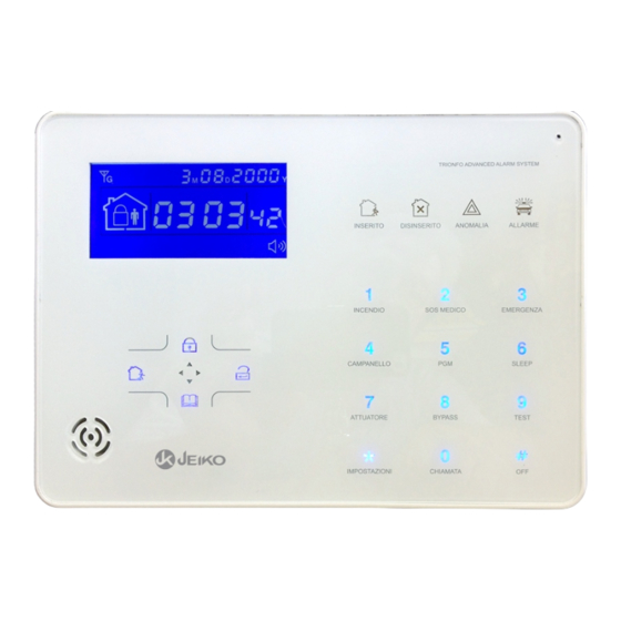
INTRODUZIONE CAPITOLO 1 1.1 CARATTERISTICHE PRINCIPALI 1.1.1 Guida vocale per programmazione e operazioni d’uso. 1.1.2 Regolazione volume della guida vocale 1.1.3 Interfaccia utente : LCD display grafico con icone & indicatori stato 1.1.4 Combinatore telefonico PSTN 1.1.5 Combinatore telefonico GSM 1.1.6 Selezione priorità... -
Page 9: 1.1.42 Caratteristiche Principali
INTRODUZIONE CAPITOLO 1 CARATTERISTICHE PRINCIPALI 1.1.22 Riconoscimento tipo di allarme :in allarme il display indica la zona in allarme, il tipo di allarme e l’icona. 1.1.23 Controllo remoto : interagibilita’ a distanza tramite telefono e SMS 1.1.24 Sistema di supervisione antimanomissione 1.1.25 Sistema di supervisione per controllo funzionamento sensori wireless e livello batteria sensori stessi. -
Page 10: 1.1.53 Caratteristiche Principali
INTRODUZIONE CAPITOLO 1 CARATTERISTICHE PRINCIPALI 1.1.43 Tasto diretto per lanciare avviso allarme Incendio 1.1.44 Tasto diretto per lanciare allarme Emergenza 1.1.45 Tasto diretto per lanciare allarme SOS medico 1.1.46 Tasto per controllo diretto porta PGM 1.1.47 Tasto per controllo diretto attuatori 1.1.48 Tasto diretto per bypass zone 1.1.49 Tasto per utilizzo centrale come telefono 1.1.50 Indicatore di anomalia... -
Page 11: Capitolo 2 Installazione E Collegamenti
INSTALLAZIONE & COLLEGAMENTI CAPITOLO 2 2.1 INSTALLAZIONE Posizionamento e installazione della centrale di allarme Prima di procedere con l'istallazione della centrale di allarme, ė consigliabile osservare i seguenti punti sotto menzionati: *.Individuare un punto con presa di alimentazione a 220 Volt per poter collegare l'alimentare AC/DC alla centrale di allarme e possibilmente vicino ad una presa telefonica per collegare il cavo per il combinatore telefonico incorporato. - Page 12 INSTALLAZIONE & COLLEGAMENTI CAPITOLO 2 Installazione della centrale di allarme. 2.1.1 Rimuovere la staffa della centrale d’allarme spingendola verso il basso e seguendo le istruzioni riportate nella figura a seguito. Passaggio cavi Antimanomissione Passaggio cavi 2.1.2 Inserire la SIM card con i contatti rivolti verso il basso ACCERTARSI CHE LA SIM CARD NON NECESSITI DEL PIN IN CASO CONTRARIO ANNULLARE IL PIN DELLA SIM CARD UTILIZZANDO UN TELEFONO GSM.
-
Page 13: Connessioni (N.a. N.c)
INSTALLAZIONE & COLLEGAMENTI CAPITOLO 2 CAPITOLO 2 2.2 CONNNESSIONI Effettuare i collegamenti come da figura a seguito riportata. Collegare il cavo della linea telefonica ed il telefono nelle prese dedicate Inserire il jack di alimentazione nell’apposita presa ed inserire l’alimentatore nella presa di corrente a muro. Collegare l’antenna GSM prestando molta cura ed attenzione all’inserimento del connettore. - Page 14 INSTALLAZIONE & COLLEGAMENTI CAPITOLO 2 2.2 CONNESSIONI NC e NO PER SENSORI FILARI Fare riferimento allo schema riportato nella figura seguente : NC 10K Volume guida vocale PGM GND Z33 Z34 GND Z35 Z36 Z37 Z38 GND Z39 Z40 DC15V/2A Power T E L L I N E...
-
Page 15: Installazione Sensori Filari
INSTALLAZIONE & COLLEGAMENTI CAPITOLO 2 2.3 INSTALLAZIONE SENSORI FILARI La programmazione di fabbrica prevede le zone filari disattivate. Provvedere ad attivarle per utilizzarle. 2.3.1 Nel caso di malfunzionamento di una zona filare, all’inserimento del sistema la guida vocale scandirà il messaggio << Operazione fallita Zona problema>>... -
Page 16: Capitolo 3 Tastiera E Funzioni
TASTIERA & FUNZIONI CAPITOLO 3 3.1 UTILIZZO DEL SISTEMA Password amministratore predefinita: 012345 Questo sistema supporta fino a 16 utenti: • Utente 1: Password Utente Master predefinita è 1234. • Utenti 2 – 16: Utenti di sistema. NB solo l’utente master Nr.1 è abilitato ad accedere al menu utente 3.1.1 INSERIMENTO - DISINSERIMENTO SISTEMA... -
Page 17: Tasti Emergenza
TASTIERA & FUNZIONI CAPITOLO 3 3.1.2 TASTI DI EMERGENZA Per attivare un allarme, tenere premuto il tasto di emergenza appropriato per tre secondi. Opzioni Comando Azione ALLARME Premere il tasto Pannello centrale INCENDIO per 3 secondi Premere il tasto Pannello centrale per 3 secondi MEDICO Telecomando... -
Page 18: Funzioni Dirette
TASTIERA & FUNZIONI CAPITOLO 3 3.1.4 FUNZIONE CAMPANELLO DELLE ZONE RITARDATE Premere per tre secondi il tasto inserire la password seguita dal tasto enter per attivare / disattivare la funzione campanello delle zone ritardate (rif. pag.54 del manuale d’installazione) Seguire la guida vocale. -
Page 19: Funzioni Dirette Menu Utente
TASTIERA & FUNZIONI CAPITOLO 3 3.1.9 TEST DI FUNZIONAMENTO GSM ,SIRENA, SENSORI, Premere per tre secondi il tasto inserire la password digitare .seguita dal tasto enter Seguire la guida vocale passo passo. e selezionare il tipo di test da eseguire : 1 Comunicazione, 2 Sirena, 3 sensori.Utilizzare i test per verificare il regolare funzionamento di comunicazione con l’istituto di vigilanza , delle sirene, dei sensori. -
Page 20: Controllo Eventi
CONTROLLO & SEGNALAZIONI CAPITOLO 3 3.1.14 CONTROLLO EVENTI MEMORIZZATI Premere il tasto [ ] il display visualizzerà l’ultimo evento registrato. Premere il tasto [ ] per visualizzare in sequenza gli eventi precedenti, premere il tasto [ ] per visualizzare gli eventi successivi. -
Page 21: Segnalazione Della Centrale
CONTROLLO & SEGNALAZIONI CAPITOLO 3 SEGNALAZIONI DELLA CENTRALE D’ALLARME 3.1.15 INDICATORI SEGNALAZIONE Lampeggiante ANOMALIA: MANCANZA DI RETE ELETTRICA ANOMALIA : RILEVATO UN PROBLEMA SULLA ZONA INDICATA SUL DISPLAY . Lampeggiante PROCEDURA D’ALLARME IN CORSO ICONA SEGNALAZIONE DISPLAY Lampeggiante Fissa ANOMALIA: RETE GSM PRESENTE MANCANZA DI RETE GSM Lampeggiante... -
Page 22: Evento E Procedura D'allarme
CONTROLLO & SEGNALAZIONI CAPITOLO 3 ICONA SEGNALAZIONE DISPLAY INDICAZIONE LIVELLO SEGNALE GSM ANOMALIA : BATTERIA SCARICA DELLA CENTRALE D’ALLARME EVENTO D’ALLARME ACCADUTO GENERATO DALLA ZONA 5 ANOMALIA : SENSORE CON BATTERIA SCARICA NELLA ZONA 5 INDICATA SUL DISPLAY ANOMALIA : MANCATA SUPERVISIONE DELLA ZONA 5 INDICATA SUL DISPLAY ANOMALIA :... -
Page 23: Capitolo 4 Avviso Di Allarme
PROCESSO D’ALLARME CAPITOLO 3 3.1.16 EVENTO D’ALLARME & PROCEDURA CMS centrale vigilanza Telefono Telefono Telefono cellulare 2. La centrale d’allarme chiama i numeri Rete Telefonica telefonici programmati e nel contempo aziona la sirena. Centrale vigilanza privata 1. I sensori inviano il segnale d’allarme alla centrale d’allarme 3. -
Page 24: Procedura D'allarme Con Combinatore Telefonico Rete Fissa
CONTROLLO & SEGNALAZIONI CAPITOLO 4 AVVISO DI ALLARME TRAMITE COMBINATORE TELEFONICO In caso d’allarme, il combinatore telefonico effettuerà le chiamate ai numeri da voi memorizzati (parenti, amici, vicini, per un massimo di 4 numeri telefonici) allerterà , in sintesi vocale, con il messaggio da Voi registrato. -
Page 25: Gestione Remota Con Linea Fissa
GESTIONE REMOTA CAPITOLO 4 4.3 GESTIONE REMOTA VIA TELEFONO CON LINEA FISSA Chiamate il numero telefonico di rete fissa dove è collegata la centrale.Dopo aver digitato il numero telefonico , la centrale di allarme si collegherà dopo gli squilli programmati (default 7 squilli). Successivamente la guida vocale della centrale di allarme richiederà... -
Page 26: Gestione Remota Tramite Messaggi Sms
GESTIONE REMOTA CAPITOLO 4 4.5 GESTIONE REMOTA TRAMITE MESSAGGI SMS Il combinatore GSM consente all’utente di interagire con la centrale d’allarme tramite i messaggi SMS. Si possono impartire i seguenti comandi che la centrale d’allarme eseguirà e confermerà con messagg i SMS l’avvvenuta esecuzione. OPERAZIONI COMANDI SMS password:1234 TOTALE... - Page 27 GESTIONE REMOTA CAPITOLO 4 COMANDI SMS RISPOSTE DA CENTRALE Inserimento totale effettuato password:1234 TOTALE Inserimento totale fallito Inserimento parziale effettuato password:1234 PARZIALE Inserimento parziale fallito Disinserimento effettuato password:1234 SPENTO Disinserimento fallito Sistema totale inserito, password:1234 STATO Sistema parziale inserito,Sistema disinserito Allarme cancellato password:1234 STOP Cancellazione allarme fallita...
-
Page 28: Messaggi Sms
SEGNALAZIONI SMS CAPITOLO 4 Allarme emergenza medica Batteria sensore scarica Batteria sensore OK Allarme zona ritardata Allarme zona perimetrale Mancata supervisione Allarme zona interna Batteria centrale allarme scarica Allarme zona emergenza Batteria centrale allarme OK Allarme zona 24ore Mancanza rete elettrica Rete elettrica ripristinata Allarme zona incendio Allarme manomissione... -
Page 29: Capitolo 5 Menu Utente
MENU UTENTE CAPITOLO 5 MENU IMPOSTAZIONI UTENTE Premere per tre secondi il tasto inserire la password digitare seguita dal tasto enter Seguire la guida vocale passo passo. e selezionare l’operazione da eseguire : 1 imposta orologio, 2 Imposta password utente,3 imposta numeri telefonici. Menu UTENTE Premere[*]per 3 secondi Imposta orologio... -
Page 30: Impostazione Password Utente
MENU UTENTE CAPITOLO 5 5.2 IMPOSTAZIONE PASSWORD UTENTE Per esempio impostare la password numero 16 codice 5678 Premere[*] per 3 secondi 1 imposta orologio 2 imposta password Digitare la password utente 3imposta numeri telefonici inserire il numero premere il tasto OUT utente da 01 a 16 per uscire dal menu premere # per... -
Page 31: Impostazione Numeri Telefonici
MENU UTENTE CAPITOLO 5 5.3 IMPOSTAZIONE NUMERI TELEFONICI Per esempio impostare la password numero 16 codice 5678 Premere[*] per 3 secondi 1 imposta orologio 2 imposta password Digitare la password utente 3imposta numeri telefonici premere il tasto OUT per uscire dal menu imposta numeri telefonici [5] Imposta [6] Imposta... -
Page 32: Capitolo 6 Impostazioni Sistema
IMPOSTAZIONE SISTEMA CAPITOLO 6 Menu AMMINISTRATORE 1 Imposta password Premere[*]per 3 secondi 2 Imposta istituto di vigilanza Digitare la password 3 Imposta i numeri telefonoci 4 imposta opzioni di sistema 5 imposta dispositivi wireless 6 imposta zone 7 manutenzione del sistema 8 imposta GSM 9 imposta opzioni avanzate 6.1 IMPOSTAZIONE PASSWORD... - Page 33 IMPOSTAZIONE SISTEMA CAPITOLO 6 Note: 1. impostazione password include "Password utente" e "Password amministratore", la password utente si usa principalmente per disinserire il sistema, ed è il codice richiesto per l’accesso alla gestione remota della centrale. La "Password amministratore" è l'unica password per accedere al menu d’impostazioni di sistema.
-
Page 34: Impostazione Istituto Vigilanza
IMPOSTAZIONE SISTEMA CAPITOLO 6 6.2 IMPOSTAZIONE ISTITUTO DI VIGILANZA Premere[*]per 3 secondi Digitare la password Seguire la guida vocale e digitando i comandi selezionati Imposta l’istituto di vigilanza [1]imposta ]imposta [3]imposta ]imposta ]imposta intervallo 1* numero 2* numero identificativo utente numero chiamate test di comunicazione Istituto di vigilanza... -
Page 35: Impostazione Numeri Telefonici
IMPOSTAZIONE SISTEMA CAPITOLO 6 Esempio : La centrale d’allarme è collegata ad un centralino telefonico , il numero di telefono dell’istituto di vigilanza è 80808080, in questo caso l’impostazione sarà al seguente 9P80808080, 9 è il codice richiesto dal centralino per rilasciare la linea telefonica. -
Page 36: Impostazione Opzioni Di Sistema
IMPOSTAZIONE SISTEMA CAPITOLO 6 Note: 1. I cicli di chiamate possono essere impostati da 1 a 15. 2.In caso di allarme quando la centrale chiama i telefoni memorizzati se avete impostato la richiesta password, gli utenti dovranno digitare la password per interagire con la centrale d’allarme . Esempio :Imposta il terzo numero di telefono : 12345678 Premere[*]per 3 secondi Digitare la password... -
Page 37: Impostazioni Orologio
IMPOSTAZIONE SISTEMA CAPITOLO 6 6.4.1 IMPOSTAZIONE OROLOGIO Esempio tempo da impostare: 23 Novembre 2013 ore 20:59 e 36 secondi Premere[*]per 3 secondi Digitare la password Seguire la guida vocale e digitando i comandi selezionati digita data e ora premi # per salvare premi OUT per uscire Anno Mese... -
Page 38: Impostazione Ritardo D'uscita
IMPOSTAZIONE SISTEMA CAPITOLO 6 6.4.3 IMPOSTAZIONE RITARDO D’USCITA Dopo aver inserito l'allarme ,parte il count down del ritardo d’uscita, durante il quale nessuna intrusione viene rilevata, questo permette all’utente di uscire comodamente dalla abitazione senza provocare allarmi indesiderati. (ritardo predefinito 10sec.) Esempio ritardo d’uscita da impostare: 20 secondi Premere[*]per 3 secondi Digitare la password... -
Page 39: Impostazione Intervallo Supervisione Sensori
IMPOSTAZIONE SISTEMA CAPITOLO 6 Esempio squilli alla risposta da impostare:5 squilli Premere[*]per 3 secondi Digitare la password Digita numero squilli alla risposta inserendo zero il sistema non Impostazioni risponde,premi # per salvare salvate premi OUT per uscire digita gli squilli con un numero di 2 cifre da 00-15 6.4.6 IMPOSTAZIONE INTERVALLO SUPERVISIONE SENSORI La centrale supervisiona i sensori ad ogni intervallo di tempo impostato se la centrale non riceve il segnale dai sensori entro il tempo impostato... -
Page 40: Impostazione Report Inserimento Disinserimento
IMPOSTAZIONE SISTEMA CAPITOLO 6 Esempio impostare sirena per annuncio inserimento / disinserimento Premere[*]per 3 secondi Digitare la password Seleziona annuncio sirena, premi 1 per annuncio Impostazioni premi 2 per nessun annuncio salvate premi # per salvare premi OUT per uscire 6.4.8 IMPOSTAZIONE REPORT INSERIMENTO DISINSERIMENTO ttivare il report d’avviso all’Istituto di vigilanza per inserimento /... -
Page 41: 1Impostazione Suono Sirena Per Emergenze
IMPOSTAZIONE SISTEMA CAPITOLO 6 6.4.9.1 IMPOSTAZIONE SUONO SIRENA PER LE EMERGENZE (programmazione di fabbrica e’ muto). Esempio suono sirena da impostare: continuo Premere[*]per 3 secondi Digitare la password Per tipo suono sirena seleziona :1.per continuo Impostazioni 2.per intermittente salvate 3. per muto premi #per salvare premi OUT per uscire 6.4.9.2 IMPOSTAZIONE TEMPO DI CONTROLLO MANCANZA... -
Page 42: Imposta Controllo Antimanomissione Periferiche
IMPOSTAZIONE SISTEMA CAPITOLO 6 6.4.9.4 IMPOSTA CONTROLLO ANTIMANOMISSIONE PERIFERICHE Con controllo abilitato, qualora si manometta una periferica o un sensore wireless la centrale attiva la procedura d’allarme. ( l’impostazione di fabbrica è controllo abilitato) Esempio disattivare il controllo antimanomissione Premere[*]per 3 secondi Digitare la password seleziona : premi 1 controllo antimanomissione attivo,... -
Page 43: Imposta Allarmi Consentiti Per Zona 3
IMPOSTAZIONE SISTEMA CAPITOLO 6 6.4.9.7 IMPOSTA ALLARMI CONSENTITI PER ZONA impostando un allarme consentito per zona, dopo aver generato un allarme la medesima zona anche se violata nuovamente non genererà alcun allarme. Esempio impostare 1 allarme consentito per zona. Premere[*]per 3 secondi Digitare la password per numero di allarmi per zona seleziona : 1 per nessuna limitazione,... -
Page 44: Imposta Dispositivi Wireless
IMPOSTAZIONE SISTEMA CAPITOLO 6 6.5 IMPOSTA DISPOSITIVI WIRELESS Imposta telecomando Premere[*]per 3 secondi Imposta sensori wireless Imposta attuatori wireless Registra sirena wireless Imposta sensore per campanello 6.5.1 IMPOSTA TELECOMANDO Registrazione automatica Premere[*]per 3 secondi telecomando Registrazione manuale telecomando Cancella telecomando 6.5.1.1 REGISTRA TELECOMANDO AUTOMATICAMENTE Esempio: registra automaticamente il telecomando in posizione 3 Premere[*]per 3 secondi... -
Page 45: Cancella Telecomando
IMPOSTAZIONE SISTEMA CAPITOLO 6 6.5.1.3 CANCELLA TELECOMANDO Esempio: cancella il telecomando in posizione 5 Premere[*]per 3 secondi Digitare la password Digita il numero del telecomando da cancellare Impostazioni salvate digita zero per cancellarli tutti Premi # per salvare, Premi OUT per uscire 6.5.2 IMPOSTA SENSORI WIRELESS Premere[*]per 3 secondi Registrazione automatica... -
Page 46: Registra Sensori Manualmente
IMPOSTAZIONE SISTEMA CAPITOLO 6 6.5.2.2 REGISTRA SENSORE MANUALMENTE Esempio: registra manualmente il sensore 011022033 in posizione 7 Premere[*]per 3 secondi Digitare la password Digita il numero della zona da 01 a 32 in cui registrare il sensore Premi # per confermare, Premi OUT per uscire Digita seriale sensore Premi # per salvare,... -
Page 47: Registra Attuatori Wireless
IMPOSTAZIONE SISTEMA CAPITOLO 6 6.5.3.1 REGISTRA ATTUATORI WIRELESS Esempio: registra l’attuatore in posizione 1 Premere[*]per 3 secondi Digitare la password Inserire il numero dell’attuatore Premi # per confermare, Premi OUT per uscire Prego azionare l’attuatore Premi il tasto OUT Azionare il sensore per uscire dal menu Registrazione riuscita... -
Page 48: Cancella Sirena Wireless
IMPOSTAZIONE SISTEMA CAPITOLO 6 6.5.4.1 REGISTRA SIRENA WIRELESS Premere[*]per 3 secondi Digitare la password Prego impostare la sirena impostare la sirena in modalità apprendimento in modalità dopodichè premere il tasto # per apprendimento registrare la sirena premere il tasto OUT per tornare al menu precedente Questa è... -
Page 49: Imposta Sensore Per Campanello
IMPOSTAZIONE SISTEMA CAPITOLO 6 6.5.5 IMPOSTA SENSORE PER CAMPANELLO Registra campanello Cancella campanelllo 6.5.5.1 REGISTRA CAMPANELLO Premere[*]per 3 secondi Digitare la password Prego azionare Azionare il registrazione campanello,premere il campanello riuscita tasto OUT per uscire dal Impostazioni menu. salvate Nota: si possono registrare solo campanelli wireless 6.5.5.2 CANCELLA CAMPANELLO Premere[*]per 3 secondi Digitare la password... -
Page 50: Imposta Proprietà Zone
IMPOSTAZIONE SISTEMA CAPITOLO 6 6.6.1 IMPOSTA PROPRIETA’ ZONE Le proprietà assegnabili ad ogni zona sono le seguenti : 0>zona disabilitata 1> zona ritardata 2> zona perimetrale 3>zona interna 4>zona emergenza 5> zona attiva 24ore 6>zona incendio 7> zona chiave La proprietà assegnata alla zona corrisponde al tipo di allarme segnalato dal LCD display della centrale quando la zona rileva l’intrusione. -
Page 51: Imposta Suono Sirena
IMPOSTAZIONE SISTEMA CAPITOLO 6 6.6.2 IMPOSTA SUONO SIRENA Esempio : Imposta la zona 23 con sirena intermittente Premere[*]per 3 secondi Digitare la password Digita il numero della zona da programmare Premi # per confermare, Premi OUT per uscire Per tipo suono sirena seleziona : Impostazioni 1.per Continuo 2.per Intermittente 3.per muto salvate... -
Page 52: Imposta Tempo Risposta Zone Filari
IMPOSTAZIONE SISTEMA CAPITOLO 6 Esempio : Imposta la zona 35 con proprietà «NO Normalmente aperta» Premere[*]per 3 secondi Digitare la password Per funzionamento zona Digita il numero della filare seleziona : zona da programmare 1.Con resistenza Premi # per confermare, 2.Normalmente chiusa Premi OUT per uscire 3.Normalmente Aperta... - Page 53 IMPOSTAZIONE SISTEMA CAPITOLO 6 Se la zona B rileva l’intrusione ed in seguito la zona A rileva l’intrusione , il sistema NON attiva la procedura d’allarme. 2>EXIT ROUTE Se la zona A rileva l’intrusione, il sistema attiva la procedura d’allarme. Se la zona B rileva l’intrusione ed entro l’intervallo di tempo stabilito la zona A rileva l’intrusione il sistema NON attiva la procedura d’allarme.
-
Page 54: Manutenzione Del Sistema
IMPOSTAZIONE SISTEMA CAPITOLO 6 6.7. MANUTENZIONE DEL SISTEMA Imposta tempo autoinserimento e disinserimento Premere[*]per 3 secondi Registrazione messaggio Ascolto messaggio registrato Imposta le funzioni dell’uscita PGM Cancella gli eventi registrati Ripristino impostazioni di fabbrica 6.7.1 IMPOSTA TEMPO AUTOINSERIMENTO & DISINSERIMENTO Esempio : Imposta come periodo 3 tempo disinserimento 8,30 e tempo inserimento 17,30. -
Page 55: Ascolto Messaggio Registrato
IMPOSTAZIONE SISTEMA CAPITOLO 6 6.7.3 ASCOLTO MESSAGGIO REGISTRATO Premere[*]per 3 secondi Digitare la password riproduzione messagggio 6.7.4. IMPOSTA LE FUNZIONI DELL’ USCITA PGM La tensione in uscita dalla Porta PGM passerà da 0V a 14.5V non appena accadrà l’evento selezionato . (la programmazione di fabbrica è... -
Page 56: Cancella Eventi Registrati
IMPOSTAZIONE SISTEMA CAPITOLO 6 6.7.5 CANCELLA GLI EVENTI REGISTRATI Premere[*]per 3 secondi Digitare la password riconferma la cancellazione Impostazioni degli eventi. salvate Premi # per salvare, Premi OUT per uscire 6.7.6 RIPRISTINO IMPOSTAZIONI DI FABBRICA Premere[*]per 3 secondi Digitare la password riconferma il ripristino delle impostazioni di fabbrica Impostazioni... - Page 57 IMPOSTAZIONE SISTEMA CAPITOLO 6 Imposta GSM [2]Imposta [3] Mostra il Imposta Abilita o priorità dei livello del disabilita il GSM avviso scadenza combinatori segnale GSM SIM card telefonici Seleziona Seleziona Digita la data di Premi OUT per 1> abilita il GSM 1>...
-
Page 58: Imposta Opzioni Avanzate
IMPOSTAZIONE SISTEMA CAPITOLO 6 6.9 IMPOSTA OPZIONI AVANZATE Impostate le opzioni avanzate digitando i due digit di indirizzo programmazione e le opzioni corrispondenti come riportate nella tavola seguente. Queste impostazioni avanzate sono prive di guida vocale. 59 Sensore ripristinato GPRS abilitato e disabilitato 60 Perdita Sensore Imposta l’indirizzo IP del server GPRS 61 Batteria centrale scarica... -
Page 59: Attiva & Disattiva Gprs
IMPOSTAZIONE SISTEMA CAPITOLO 6 ndicazioni del LCD display Indirizzo Dato Nr. digit programmazione Premere i tasti per controllare e modificare i dati del Nr.digit 6.9.1 ATTIVA & DISATTIVA GPRS. 1. Attiva 2. Disattiva . (la programmazione di fabbrica è GPRS disattivato.) Esempio :attiva GPRS Premere[*]per 3 secondi Digitare la password... -
Page 60: Imposta La Porta Del Server
IMPOSTAZIONE SISTEMA CAPITOLO 6 6.9.3 IMPOSTA LA PORTA DEL SERVER Esempio: imposta la porta del server come 80808 Premere[*]per 3 secondi Digitare la password inserire il dato con max 5 digit. 6.9.4 IMPOSTA IDENTIFICATIVO UTENTE Esempio : Identificativo utente : 50505050 Premere[*]per 3 secondi Digitare la password inserire il dato d 8 digit. -
Page 61: Imposta Tono Campanello Per Zone Ritardate
IMPOSTAZIONE SISTEMA CAPITOLO 6 6.9.7 IMPOSTA TONO CAMPANELLO PER ZONE RITARDATE 1. Dingdong 2. Benvenuto 3. Messaggio registrato 4. Didi Esempio :Imposta il tono campanello x zone ritardate come : registrazione Premere[*]per 3 secondi Digitare la password Nota: A sistema disinserito, quando la zona ritardata rileva l’intrusione il tono del campanello generato sarà... - Page 62 IMPOSTAZIONE SISTEMA CAPITOLO 6 6.9.10 IMPOSTA ILLUMINAZIONE DISPLAY IN STAND-BY (impostazione di fabbrica è 02) Esempio: imposta l’illuminazione display come 08 Premere[*]per 3 secondi Digitare la password Range illuminazione : 01-10. inserire il dato con 2 digit (esempio 08). 6.9.11 IMPOSTA PERIODO DI RITENZIONE EVENTO D’ALLARME Qualora la linea telefonica fissa e la rete GSM non fossero momentaneamente disponibili, l’evento d’allarme verrà...
-
Page 63: Dati Generali
Le specifiche tecniche sono soggette a modifiche senza preavviso. DK Digital Italia srl dichiara che questo sistema di allarme senza fili JEIKO Mod. Trionfo è conforme ai requisiti essenziali della direttiva europea: R&TTE 1999/5/EC ed in particolare è conforme alle seguenti normative: ETSI EN 300 220-1;... - Page 64 LIMITI E MANUTENZIONE CAPITOLO 8 LIMITI Neppure il più avanzato sistema di sicurezza può garantire una copertura totale contro intrusione, incendio o minacce ambientali. Tutti i sistemi di sicurezza possono fallire nel loro compito di segnalazione per svariati motivi, fra cui, ma non solo, i seguenti: •...
- Page 65 Assistenza Tecnica / Help Line +39 031 712304 Attivazione del servizio di assistenza Comfort : Per usufruire dei servizi contemplati dalla garanzia COMFORT , registratevi nel sito www.jeiko .eu nella sezione assistenza Comfort.
- Page 66 NOTE D’INSTALLAZIONE CAPITOLO 10 Password Password Password Password Descrizione Descrizione Descrizione Descrizione Utente Utente Utente Utente di accesso di accesso di accesso di accesso User User User User Password Password Description Description Password Password Description Description master master...
- Page 67 NOTE D’INSTALLAZIONE CAPITOLO 10...
- Page 68 NOTE D’INSTALLAZIONE CAPITOLO 10...
- Page 69 TROUBLE SHOOTING CAPITOLO 11 Centrale d’allarme non funziona-il led power è spento 1 Manca corrente- controllare la presenza di corrente nella presa a muro. 2 Controllare che il jack dell’adattatore sia inserito nella centrale. Centrale d’allarme rifiuta il Password utente 1 Avete digitato una Password errata 2 Digitare la password amministratore e verificare la password utente memorizzata e verificarne la correttezza.
- Page 70 TROUBLE SHOOTING CAPITOLO 11 Telecomando non funziona . 1 Verificare l’accensione del Led di indicazione. 2 Assicuratevi che la batteria sia inserita con la corretta polarità e che la batteria abbia un contatto stabile con il portabatteria stesso. 3 Batteria scarica - sostituire la batteria. Falso allarme sensore di movimento PIR /PIT/POU.
- Page 71 TROUBLE SHOOTING CAPITOLO 11 Centrale non chiama i numeri memorizzati ad allarme in corso. 1 La linea telefonica non è collegata o non funziona - controllare la linea telefonica con un telefono. 2 I numeri telefonici non sono stati memorizzati correttamente. 3messagio di allarme non memorizzato.
- Page 72 TROUBLE SHOOTING CAPITOLO 11 Informazione: SIM CARD Scaduta Informazione : SEGNALE debole Informazione : Registrazione RETE fallita Informazione : GSM non risponde Informazione : SIM CARD difettosa Informazione : Problemi di connessione GSM Malfunzionamento del combinatore GSM determinato dal livello di segnale GSM debole Sel’LCD display mostra le seguenti informazioni , Informazione : SEGNALE debole Verificare l’intensità...
- Page 73 Jeiko Trionfo system uses in the alarm signal on the common high speed way CONTACT ID make appilcation of this series of product wider and compatibility stronger.
- Page 74 User manual Ê ² Æ ² Content Chapter I Introduction Chapter 2 Installation and Connection Installation Connection(N.O. N.C) Install wired detector 2.4 Intall wereless detector Chapter 3 Keybad and Operation 3.1 About panel Basic operation 3.3 Flashes when phone line cut 3.4 Host arm and disarm 3.5 Alarm procedure Chapter IV Voice alarm receiving...
- Page 75 User manual Ê ² Æ ² 6.4.2 Set entry delay 6.4.3 Set exit delay 6.4.4 Set siren time 6.4.5 Set ring times 6.4.6 Set detector loss inspection 6.4.7 Set arm/disarm tone 6.4.8 Set arm/disarm report 6.4.9 Set others 6.4.9.1Set emergency alarm siren type 6.4.9.2 Ac off inspection time setting 6.4.9.3 Magnetic contact inspection 6.4.9.4 Check wireless detector tamper...
- Page 76 User manual Ê ² Æ ² 6.6.1 Set zone attribution 6.6.2 Set zone siren type 6.6.3 Set wired zone loop type 6.6.4 Set wired zone response speed 6.6.5 Set related zone 6.7 System maintance 6.7.1 Set timing operation 6.7.2 Recording 6.7.3 Play recording 6.7.4 Set programmable output port 6.7.5 Delete system events...
-
Page 77: Chapter I Introduction
User manual Ê ² Æ ² Chapter I Introduction 1.1 Function Introduction 、 I Alarm mode: with PSTN and GSM network alarm, GSM network with GPRS function(GPRS function is for China market only), remote arm and disarm panel through CMS or SMS CID protocol, SMS notification, the priority of PSTN and GSM network is Optional. -
Page 78: Set Listen-In Time
User manual Ê ² Æ ² 13、Wireless zones, each wireless zone can automatically learn the codes or be coded manually via the keyboard. 14、8 wired zones, User can set the circuit type and speed of response, support N.O and N.C. 15、Enable enroll total 8 wireless remote,8 electronic switch,1 pc of wirele- ss doorbell and Unlimited for quantity of one way wireless siren. - Page 79 User manual Ê ² Æ ² 26、 The tampering alarm: cut the cable between wired detectors and the panel will trigger alarm, the telephone line cut will autom atically trigger siren alarm. When someone deliberately dismantled the panel, it will alarm when triggering tamper switch at the back of the panel.
-
Page 80: Chapter 2 Installation And Connection
User manual Ê ² Æ ² Chapter 2 Installation and Connection Installation the bracket to the wall and hang the panel to the bracket The large metal objects can not be placed around the panel, so as not to affect the wireless signal. Make sure to place the panel within the wireless range of all wireless accessories and pay attention to the hidden Connection(N.O. -
Page 81: Intall Wereless Detector
User manual Ê ² Æ ² To arm the panel. The zone number will be also display on the LCD screen. At this time arm system is not allowed unless you force arm. 2.3.2 The control panel can power 15V, 100mA to detectors. The max curent is 100mA. - Page 82 User manual Ê ² Æ ² Arm led: Light on under armed status, Light flashes under stay status. Disarm led: Light on under disarmed status Trouble led: Light on when with zone trouble. Light flashes when AC cut. Alarm led: Light flashes when alarm. :Press 3 seconds to trigger fire alarm :Press 3 seconds for medical help :Press 3 seconds for SOS...
-
Page 83: Basic Operation
User manual Ê ² Æ ² Basic operation Factory default Administrator password: 012345 16 User passwords, NO. 01 factory default is 1234. No. 02-16 of the user password is blank and can not enter the user setting untill user set the password. -
Page 84: Host Arm And Disarm
User manual Ê ² Æ ² Flashes when phone line cut. Light on when phone line is normal. Flashes when GSM not ready, Light on when GSM is normal. Flashes when GPRS disconnected with CMS. Light on when GPRS is connected well with CMS. - Page 85 User manual Ê ² Æ ² √ Home Arm √ Panic ~DI~ ~DI~ Press the key for home arm on the Press the panic button on remoter,or remote or "HOME"key on the keypad, " press" key on panel for 3 "s "...
-
Page 86: Alarm Procedure
User manual Ê ² Æ ² 3.5 Alarm procedure Telephone telephone Cell phone Tele 3.The panel will dial 1-4 telephone numbers as preset.If more than 4 numbers,the panel will start with second telephone number, then 3,4... Alarm software 1.The detector activated Alarm situation found, send alarm infor start to send message... -
Page 87: Chapter Iv Voice Alarm Receiving And Gsm Control
User manual Ê ² Æ ² Chapter IV Voice alarm receiving and GSM control 4.1 Remote phone control User can remote control the system by phone call, after the preset ringing times then panel will off hook the phone then enter the 4 digit user codes according to voice prompting and operate as per the voice prompting. -
Page 88: Gsm Remote Operation
User manual Ê ² Æ ² 4.3 GSM remote operation When alarm occurs, GSM will call the preset voice number, when pick up the call,enter 4 digit user code, then voice prompt: Press 1 to arm system, Press 2 to disarm system, Press 3 to Stay arm, Press 4 to check system status, Press 5 to appliance switch control, Press 9 to talk-back, Press 0 to Disconnect. -
Page 89: Chapter Iv Voice Alarm Receiving And Gsm Control
User manual Ê ² Æ ² Chapter IV Voice alarm receiving and GSM control Press[*] for 3 seconds Set system clock Set user password Set voice phone 5.1 Set system clock For example: set system clock as : 22:59:36 22/12/2012 Press[*] for 3 seconds Enter passord Please enter system... -
Page 90: Chapter Vi System Setting
User manual Ê ² Æ ² Chapter VI System Setting Set password Set CMS number Set voice phone Press[*] for 3 seconds Set system options Set wireless devices Set zone System maintenance Set GSM Set advanced options 6.1 Set password Press[*] for 3 seconds Then operate according to the voice prompt as below. -
Page 91: Set Cms Number
User manual Ê ² Æ ² 2.Administrator password is 6 digit, user password is 4 digit, can set 16 user passwords, corresponding password No. from 01 to 16, but No.2-16 password can’t enter user setting. 3.If forgot the password, when the alarm is powered on, for the first minute,the administrator password is 000000. -
Page 92: Set Voice Phone
User manual Ê ² Æ ² Note: 1.The user code is the identification code in CMS setting, CMS 1 and CMS 2 use the same user code; dialing times can be set 1-15 , communication inspection interval time can be set 0-999 hours, the common setting is 24 hours. -
Page 93: Set System Options
User manual Ê ² Æ ² Note:1.dialing times can set 1-15 2.When panel call user’s phone, if you enable password check, it will prompt enter user password when pick up the call. For example: Set voice phone No.3 is 12345678 Press[*] for 3 seconds Enter password Please enter phone number,... -
Page 94: Set Entry Delay
User manual Ê ² Æ ² 6.4.2 Set entry delay When trigger alarm, the panel will give delay alarm time(default setting is 10s) For example: Set entry delay to 20seconds Press[*] for 3 seconds Enter password Please enter entry delay time, press confirm key to save, press back key to exit Enter 3 digit number from 0-255, add 0 if less than 3 digit. -
Page 95: Set Detector Loss Inspection
User manual Ê ² Æ ² Press[*] for 3 seconds Enter password Enter password..Please enter ring times, if set as 0, the phone will not off hook, press confirm key to save, press back key to exit Enter 2 digit number from 0-15, add 0 if lower than 10. Note: The max. -
Page 96: Set Arm/Disarm Report
User manual Ê ² Æ ² 6.4.8 Set arm/disarm report Set if arm/disarm report to CMS or not( the default setting is disabled) For example: Set arm/disarm report to CMS Press[*] for 3 seconds Enter password Please choose arm/disarm report: 1. enable, 2. disable, press confirm key to save, press back key to exit 6.4.9 Set others... -
Page 97: Ac Off Inspection Time Setting
User manual Ê ² Æ ² 6.4.9.2 Ac off inspection time setting. When the AC power is off, delay to report to CMS(factory default delay time is 30 min) Example:set AC off inspection time as 15 min Press[*] for 3 seconds Enter password Plsease enter 0 to 255 minutes... -
Page 98: Set Telehpone Line Disconnect Remind
User manual Ê ² Æ ² Press[*] for 3 seconds Enter password Please choose: 1. Auto force 2. Forbid force arm via remote control. Press confirm key to save, pressback key to exit. 6.4.9.6 Set telephone line disconnect remind(factory default delayed siren sound remind) Example : disable telephone line disconnet remind Press[*] for 3 seconds... -
Page 99: Manage Wireless Device
User manual Ê ² Æ ² 6.4.9.9 Set AC off remind(factory default remind by SMS) Example:disable AC off remind Press[*] for 3 seconds Enter password Please choose AC off remind: 1. SMS remind 2. Voice phone remind 3. Disable Press confirm key to save, Pressback key to exit. -
Page 100: Set Detector
User manual Ê ² Æ ² 6.5.1.2enter remote control code Example: manaul enter the address code of remote 112113114 to the #8 remote in alarm pa Press[*] for 3 seconds Enter password Please enter the serial number of remote control. Press confirm key to save, Pressback key to exit. -
Page 101: Enter Detector Code
User manual Ê ² Æ ² 6.5.2.2 enter detector code Example: manual enter the address code of detector 011022033 to the # 7 detector in alarm panel Press[*] for 3 seconds Enter password P l e a s e e n t e r detector Number. -
Page 102: Delete Appliance Switch
User manual Ê ² Æ ² 6.5.3.2 Delete appliance switch Example: delete the # 4 appliance switch Press[*] for 3 seconds Enter password Please enter the serial number of appliance switch to delete, enter 0 to delete all Press confirm key to save, Pressback key to exit. -
Page 103: Set Door Bell 2
User manual Ê ² Æ ² 6.6.5 Set door bell Enroll doorbell Delete doorbell 6.5.5.1Enroll doorbell Press[*] for 3 seconds Enter password Please trigger doorbell Please trigger Enroll doorbell successful Pressback key to exit. Note: can only learn a wireless doorbell, the trigger will be issued after the chink 6.5.5.2 Delete doorbell Press[*] for 3 seconds Enter password... -
Page 104: Set Zone Attribution
User manual Ê ² Æ ² 2.interior zone only trigger alarm when the zone is triggered under system at armed status. 3.delay and perimeter zone trigger alarm when the zone is triggered under system at armed or home arm status. 4.emergency zone, 24 hours zone, fire zone will trigger alarm when system at any status 5.wireless zone can not set key zone type. -
Page 105: Set Wired Zone Response Speed
User manual Ê ² Æ ² 10K¦ 10K¦ EOL loop EOL loop N/O wiring diagram N/C wiring diagram Example: set zone 35 as N/O loop type Press[*] for 3 seconds Enter password Please choose loop type: Please enter the zone 1.EOL 2.N/C, 3.N/O number to modify Press confirm key to save,... -
Page 106: System Maintenance
User manual Ê ² Æ ² 2>EXIT-ENTRANCE single trigger model: trigger zone 1, zone 1 make alarm. Trigger zone 2 first, then during the period of related time trigger zone 1, do not make alarm. Trigger zone 2, then do not trigger zone 1 during related time, then zone 2 make alarm. -
Page 107: Set Timing Operation
User manual Ê ² Æ ² 6.7.1 Set timing operation Example: Set group No.3 as timing disarm at 8:30, and timing arm at 17:30 Press for 3 seconds Enter password Please enter timing Please enter timing arm arm time, 00 is invalid /disarm group number time.Press confirmkey to save, pressback... -
Page 108: Delete System Events
User manual Ê ² Æ ² For example: Set as password control output Press[*] for 3 seconds Enter password Please select programmable output port follow event 1.Follow alarm output 2.Follow arm output 3.Follow AC power fault output 4.Follow Communication fault output 5.Password control output Hint: when setting as password control output, press key 5 for 3 seconds, then enter the user password, the programme output port will be open... - Page 109 User manual Ê ² Æ ² Set GSM module GSM signal Set GSM bill [2]Set GSM [1]Set GSM in priority display disabled/enabled reminder time The maximum Please choose Please choose Please enter SIM signal intensity 1> enable GSM 1> GSM in priority card expiry time, can be displayed 2>...
-
Page 110: Advanced Setting Options
User manual Ê ² Æ ² 6.9 Advanced setting options Without voice prompt, programme address and the corresponding options as below table. GPRS enable and disable 59 Sensor recovery 60 Sensor loss Set sever IP address 61 System low battery Set sever port 62 System AC loss Set user ID... -
Page 111: Gprs Enable And Disable
User manual Ê ² Æ ² LCD display direction Programming Data Data bit address Press key up and down to check and modify the different data of the data bit. 6.9.1 GPRS enable and disable ( 1. Enable 2. Disable default is 2 ) For example: set enable GPRS Press[*] for 3 seconds Enter password... -
Page 112: Set Sever Port
User manual Ê ² Æ ² 6.9.3 Set sever port For example: Sever port as 80808 Press[*] for 3 seconds Enter password 6.9.4 Set user ID For example: User ID as 50505050 Press[*] for 3 seconds Enter password User ID must be 8 bits 6.9.5 Set user password For example: User password as 12345678 Press[*] for 3 seconds... -
Page 113: Delay Zone Tone Source Options
User manual Ê ² Æ ² 6.9.7 Delay zone tone source options 1. Dingdong 2. Welcome 3. Recording 4. Didi For example : Delay zone tone source as recording Press[*] for 3 seconds Enter password Hint: In disarm mode, once delay zone triggered and above 4 voices will be generated. -
Page 114: Alarm Event Retain Time
User manual Ê ² Æ ² 6.9.11 Alarm event retain time When telephone line and GSM all fault, the alarm event will be retained in the preset time. Otherwise it will loss. After telephone line and GSM recovery, it will upload to the CMS. (default time is 10 minutes). For example: set the alarm information retention time is 255 minutes Press[*] for 3 seconds Enter password... -
Page 115: Chapter Vii Technical Specification
User manual Ê ² Æ ² Chapter VII technical specification 7.1 General data 1.Power supply: 15V/2000mA 2.Built in rechargeable battery:11.1V/1000mah 3.System static current: <50mA(exclude wireless detector) 4.System alarming current: <300mA(exclude wireless high siren current) 5.System maximum output current: ●100mA(supply wireless detector) 6.Frequency:433MHz 7.Signal transmit distance: 100 meters (open area) -
Page 116: Chapter Viii Maintenance
User manual Ê ² Æ ² Chapter VIII maintenance 8.1 Regular test Design of components of the system is to reduce maintenance cost, but still it is suggested that periodical check may be carried out. 8.2 The cleanliness of control main machine Main control panel may be stained by fingers or covered by dust after using for a while. - Page 117 Activation of the service COMFORT To receive service under the COMFORT warranty that provides for the withdrawal and return of the Jeiko product by courier agreement directly to your home at no charge, register on the site in the Technical support section Comfort. www.jeiko.eu...
- Page 118 Correct disposal of batteries and the product INFORMATION FOR USERS OF DOMESTIC APPLIANCES Under Article. 13 of Legislative Decree 25 July 2005, No 151 "Implementation of Directives 2002/95/EC, 2002/96/EC and 2003/108/EC on the reduction of the use of hazardous substances in electrical and electronic products, waste disposal," and Legislative Decree 188 of November 20, 2008 "Implementation of Directive 2006/66/EC on batteries and accumulators and their waste"...
-
Page 119: Trouble Shooting
TROUBLE SHOOTING Control panel not working- Power led OFF 1 Mains powe r failure- check if other electrical appiances are operating n the same main plug. 2 Check that the DC jack of the adpter is connected o the control unit. Control panel does not accept the user Password 1 Incorrect code entered. - Page 120 TROUBLE SHOOTING PIR /PIT/POU movement detector false alarming 1 Ensure that the detector is not pointing at a source of heat or a moving object. 2 Ensure that the detector is not mounted above a radiator or heater. 3 Ensure that the detector is not facing a window or in direct sunlight. 4 Ensure that the detector is not in a draughty area.
- Page 121 TROUBLE SHOOTING GSM dialer malfunction due to weak signal If LCD display show below information , Information : WEAK SIGNAL Please check the signal strength following the below instructions: Input: 012345 LCD display Note :30 is signal strength, the Max.31, only if the signal strength above 6, then the dialer can send alarm information to CMS steadily via GSM.
- Page 122 , durante l’installazione o nel caso di malfunzionamento del vostro sistema di allarme . Email : service1@jeiko.eu (dal lunedì al venerdì dalle 09,30 alle 17,00) DK DIGITAL ITALIA s.r.l. Via Bisbino, 29 22072 Cermenate (CO) info@jeiko.eu www.jeiko.eu Cod. TRIONFO - Ed. 2014/2...
Need help?
Do you have a question about the TRIONFO and is the answer not in the manual?
Questions and answers