Table of Contents
Advertisement
Quick Links
Advertisement
Table of Contents

Related Manuals for Trinix TH2817B

Summary of Contents for Trinix TH2817B
- Page 1 OPERATION MANUAL TH2817B LCR Meter...
-
Page 2: Table Of Contents
Content CHAPTER 1 GENERAL INTRODUCTION ..................1 1.1 F ............................1 OREWORD 1.2 O .........................2 PERATING ONDITIONS 1.2.1 Power requirements .....................2 1.2.2 Opearing temperature and humidity ................2 1.2.3 Warm-up time ........................3 1.2.4 Notices..........................3 1.3 D & W ........................3 IMENSIONS EIGHT 1.4 S ..........................3 AFETY UMMARY... - Page 3 CHAPTER 4 OPERATION INSTRUCTIONS .................18 4.1 T .....................18 URNING ON THE NSTRUMENT 4.2 F .........................18 UNCTION PERATIONS 4.2.1 Primray parameter setup ...................18 4.2.2 Secondary parameter setup..................18 4.2.3 Frequency setup ......................19 4.2.4 Signal voltage ......................19 4.2.5 Measurement speed....................19 4.2.6 Trigger...........................19 4.2.7 Range setup ........................19 4.2.8 Open correction......................20...
-
Page 4: Chapter 1 General Introduction
TH2817B is a precision LCR meter with high accuracy, good stability, and wide measurement range. Controlled by a 16 bits MPU, TH2817B can be used for evaluating LCR components, materials and semiconductor devices over a wide range of frequencies (50 Hz to 100 kHz) and test signal levels (0.1V, 0.3V, 1V). -
Page 5: Operating Conditions
TH2817B has the file function to store the set parameters, limit parameters and list sweep parameters as a file in the internal nonvolatile memory, so that the setups can be easily reloaded, and the defult file will be automatically reloaded when TH2817B is turned on. -
Page 6: Warm-Up Time
TH2817B Operation Manual 1.2.3 Warm-up time More than 20 minutes after the instrument is turned on. 1.2.4 Notices Please do not operate the instrument in the place that is vibrative, dusty, under direct sunlight, or where there is corrosive air. -
Page 7: Electromagnetic Compatibility
TH2817B Operation Manual DO NOT attempt service or adjustment alone Do not attempt internal service or adjustment unless another person, capable of rendering first aid and resuscitation, is present. DO NOT substitute parts or modify instrument Because of the danger of introducing additional hazards, do not install substitute parts or perform unauthorized modifications to the instrument. - Page 8 TH2817B Operation Manual FREQ frequency go to local group execution trigger GPIB general-purpose interface Bus Handler interface index interface clear internal KBEEP kep beep KLOCK key lock primary inductance by 2-wire measurement secondary inductance by 2-wire measurement liquid crystal display...
- Page 9 TH2817B Operation Manual SREJ secondary reject SRES source resistor TRGEG trigger edge TRIG trigger reactance, imaginary part of impedance impedance θ phase angle 4-terminal pair...
-
Page 10: Chapter 2 Basic Specifications
TH2817B Operation Manual Chapter 2 Basic Specifications 2.1 Measurement Functions 2.1.1 Measurement parameters L: inductance C: capacitance R: resistance Z: impedance X: reactance D: dissipation θ: phase angle Q: quality factor 2.1.2 Combinations of measurement parameters Primary paratmeter Secondary parameters θ°... -
Page 11: Range
When the trigger mode is set to BUS trigger mode, the instrument performs a single measurement every time the *TRG common command is sent to TH2817B via GPIB. The BUS trigger mode cannot be set on the front panel. Send the TRIGger:SOURce BUS command via GPIB or RS232C to set the trigger mode to the BUS trigger mode. -
Page 12: Measurement Terminal Mode
TH2817B Operation Manual 2.1.7 Measurement terminal mode Common measurement: 4-terminal pair Hcur: high current (abbreaviation: Hc) Lcur: low current (abbreaviation: Lc) Hpot: high potential (abbreaviation: Hp) Lpot: low potential (abbreaviation: Lp) Transformer measurement: 2-terminal Hpot---Lpot: transformer’s primary (winding A) Hcur---Lcur: transformer’s secondary (winding B) Note: Make sure shielding terminals of Hcur and Lcur are reliably short with low impedance when the test fixtures or cables used don’t come standard with the instrument. -
Page 13: Output Impedance
TH2817B Operation Manual Accuracy: ±(10%×set value+2mV) 2.2.3 Output impedance 30Ω±5%, 100±5% (fixed at 100Ω source impedance at bias mode) 2.2.4 Measurement display range Parameter Display range 0.001μH~99.999kH 0.001pF~9999.9μF R, X, Z 0.0001Ω~99.999MΩ 0.0001~9.9999 0.0001~9999.9 Angle: -179.99°~179.99° θ Radian: -3.1415~3.1415 -99.999%~999.99% If non-percentage data is out of display range, it will be displayed as 99999. -
Page 14: Parameter Display
TH2817B Operation Manual AUX BIN: Primary parameter is within limits, but whose secondary parameter measurement result is not within limits. Sorting mode: ABS (absolute deviation): absolute deviation between measured result and nominal value is compared with bin limit. PER (percentage deviation): percentage deviation between measured result and nominal value is compared with bin limit. -
Page 15: Memory
TH2817B Operation Manual 2.3.6 Memory The instrument’s measurement parameter, such as frequency and level, measurement setups, comparator’s limit data can be stored in nonvolatile storage in the form of files. When they’re needed, they can be loaded directly from file menu to save time. And the latest saved and loaded file will be automatically loaded when the instrument is turned on next time. -
Page 16: Chapter 3 Panel Introductions
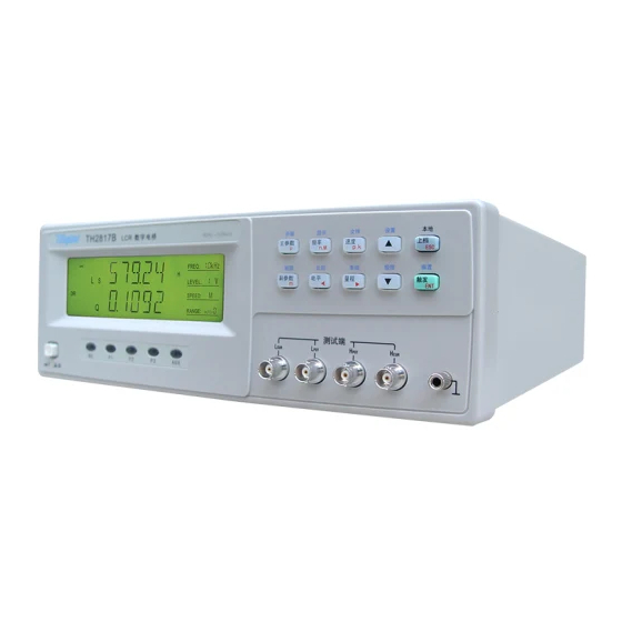
TH2817B Operation Manual Chapter 3 Panel Introductions 3.1 A Tour of Front Panel TH2817C 数字电桥 50Hz 100kHz 开路 显示 文件 设置 本地 速度 主参数 频率 ▲ 上档 μ 短路 比较 系统 极限 偏置 副参数 电平 触发 量程 测试端 Figure 3-1 Front panel overview... - Page 17 TH2817B Operation Manual In the “O” position NO operating voltages are applied to the instrument. Softkeys They have functions of three levels: a) Functions by directly pressing softkeys PARA A: to select primary parameters PARA B: to select secondary parameters...
-
Page 18: A Tour Of Rear Panel
TH2817B Operation Manual leads for measuring the device under test. HD(H ): High current drive HS(H ): High potential sense LS(L ): Low potential sense LD(L ): Low current drive Note: Make sure shielding terminals of Hcur and Lcur are reliably short with low impedance when the test fixtures or cables used don’t come standard with the instrument. -
Page 19: Display Description
It displays units of primary and secondary parameters. Inductance unit: μH, mH, H Capacitance unit: pF, nF, μF Resistance/impedance unit: mΩ, Ω, kΩ, MΩ Angle unit: Signal frequency indicator TH2817B has 10 typical frequencies from 50Hz to 100kHz. Singal level indicator... - Page 20 Secondary parameter indicator It indicates secondary parameters of the currently measured component. TH2817B has the following secondary parameters: θ° (angle), θr (radian), R, X, Q, D. 10) Comparator indicator “COMP” on: Comparator function is turned on. “COMP” off: Comparator function is turned off.
-
Page 21: Chapter 4 Operation Instructions
—— X; —— θr (radian); 4.2.2 Secondary parameter setup TH2817B has the following common secondary parameters: θ° (angle), θr (radian), R, X, Q, TH2817B also has the function of measuring DC resistance and transformer parametersw. Secondary parameters differ with parimary parameters:... -
Page 22: Frequency Setup
TRIGGER key once. 4.2.7 Range setup TH2817B totally has 9 ranges: 10Ω, 30Ω, 100Ω, 300Ω, 1kΩ, 3kΩ, 10kΩ, 30kΩ, 100k. Please select range accoding to the impedance of the device under test. Please refer to the following table for range and its corresponding measurement range. -
Page 23: Open Correction
4.2.8 Open correction Press SHIFT + OPEN to enter open correction menu. TH2817B’s open correction function can eliminate the effect of test cable, test fixture and stray admittance in parallel with the device under test, such as stray capacitance. Perform the following steps to perform open correction: 1. -
Page 24: Short Correction
4.2.9 Short correction Press SHIFT + SHORT to enter short correction menu. TH2817B’s open correction can eliminate the effect of test cable, test fixture and stray impedance in series with the device under test, such as lead resistance or lead inductance. -
Page 25: Comparator
TH2817B Operation Manual For example: 1. The current display mode is DIR, and “DIR” is displayed on LCD, as shown in Figure4-5. Figure 4-5 Direct display mode 2. Press SHIFT key, “SHIFT” at left corner is on. 3. Press DISP key, “... - Page 26 When the trigger mode is set to BUS trigger mode, the instrument performs a single measurement every time the *TRG common command is sent to TH2817B via GPIB. The BUS trigger mode cannot be set on the front panel. Send the TRIGger:SOURce BUS command via GPIB or RS232C to set the trigger mode to the BUS trigger mode.
- Page 27 TH2817B Operation Manual Press 【▲】or【▼】 to select “INT”, “MAN”, or “EXT”. DELAY Programmable delay from the trigger command to the start of the measurement, 0 to 60.000 s in 1 ms steps. Perform the following steps to set delay time (unit: ms) a) Select “DELAY”...
- Page 28 TH2817B Operation Manual Figure 4-11 Resistance selection DCHR Perform the following steps to turn on or off discharging test: Select “DCHR” through 【 】key, as shown in Figure4-12. 】or【 Press 【▲】or【▼】key to select “ON” or “OFF”. Press 【ENTER】key or 【ESC】key to exit.
-
Page 29: Limit List Setup
TH2817B Operation Manual Figure 4-15 Correction switch 4.2.13 Limit list setup TH2817B can set 3-bin limit data of primary parameter, and 1-bin limit data of secondary parameter. The comparison result can be indicated through sorting indicators: OUT: fail; pass bin 1;... - Page 30 TH2817B Operation Manual Measurement completes Higher primary parameter (PHI) Primary parameter comparison Lower primary parameter (PLO) BIN 1 comparison first; If fails, BIN 2 comparison; No pass bins FAIL BIN (OUT) If fails, BIN 3 comparison Primary parameter passes some bin...
- Page 31 TH2817B Operation Manual BIN3L: low limit of primary parameter 3; BIN3H: high limit of primary parameter 3; SEC L: low limit of secondary parameter; SEC H: high limit of secondary parameter; At limit setup page, press 【 】 key to select item, press【▲】or 【▼】 key 】or 【...
- Page 32 TH2817B Operation Manual point to twinkle, then press【▲】or【▼】key to move it. If multiple needs modifying, press 【 】key to select the unit and multiple 】or【 to twinkle, then press【▲】or【▼】key to modify multiple. After setting, press 【ENTER】key to ensure the modification, or【ESC】key to cancel it.
-
Page 33: File Operation Function
TH2817B Operation Manual Figure 4-22 Limit setup of secondary parameter 4.2.15 File operation function Perform the following steps to enter file operation page: At test status, press SHIFT key, and “SHIFT” at left corner is on. Press FILE key to enter file operation page, and the instrument first displays currently-used file No., (if no file is loaded, the default setup of file No. -
Page 34: System Function Setup
TH2817B Operation Manual Figure 4-24 Loading file ERASE Perform the following steps to erase file: Select “ERASE” at file operation page through【 】key, as shown in 】or【 Figure4-25. Press 【 ▲】 or 【▼】 key to select erasing file No. Displayed “Y” means the file has existed, and “N”... - Page 35 Press 【ESC】key to exit. Figure 4-27 Communication address setup BAUD TH2817B’s RS232C supports 8 common baud rates: 4800bps, 9600bps, 11520bps, 12800bps, 14400bps, 19200bps, 28800bps, and 38400bps. Perform the following steps to select baud rate: At system setup page, select “BAUD” through 【...
- Page 36 TH2817B Operation Manual Figure 4-28 Baud rate setup DELIM TH2817B supports to send several common ending symbols: line change symbol (ASCII ode 100); CR: enter symbol (ASCII code 13); CR+LF: enter to change line Perform the following steps to select: At system setup page, select “DELIM”...
- Page 37 】or【 4-32. Press 【▲】or【▼】key to select HOLD or CLEAR. Press 【ENTER】key or【ESC】key to exit. Figure 4-32 HANDLER interface’s signal hold ALARM TH2817B provides alarm function for sorting result. OFF: alarm off; NOGO: alarm at fail (no good); AUX: alarm at auxiliary bin;...
- Page 38 TH2817B Operation Manual There are 6 sounds available: LO.SHT: low and short; LO.LON: low and long; LO.TWO: two short and low; HI.SHT: high and short; HI.LON: high and long; HI.TWO: two short and high Perform the following steps to set sound: At system setup page, select “SOUND”...
- Page 39 TH2817B Operation Manual Figure 4-36 Keylock on/off setup After keylock is set, function keys on panel can’t be available. Press SHIFT, then SYSTEM to enter “KLOCK” operation, press 【▲】or【▼】to unlock. 12) SAVE Perform the following steps to save setups: Select “SAVE” through 【...
-
Page 40: Chapter 5 Remote Control
TH2817B has the RS232C serial interface and the parallel GPIB (optional) interface. Both interfaces can be used to remotely control TH2817B, but they can not be used at the same time. The two interfaces share the same program commands, but they have different hardware configurations and different communication protocols. -
Page 41: Communication With A Computer
9 Pin Connector Pin Number Transmitted Data Received Data Signal Ground Common TH2817B’s RS232 interface may be different with the standard RS232C. The pin configuration is shown as follows. 5.1.2 Communication with a computer Diagram of connection to a controller. DTR(4) - Page 42 TH2817B executes the command after the end character NL is received. The character received by TH2817B will be sent back to the controller again. The controller will not send the next character until the last return character is received correctively from TH2817B. If the controller cannot receive the character sent back by TH2817B, the reasons may be as follows.
- Page 43 For some commands that will take a long time to execute, for example Correction command, the controller should keep waiting to avoid the next command being lost when TH2817B is executing the former command. Sample Program for Serial Interface The following is a C language sample program under DOS environment. The main function may be expanded by users, and the other sub functions teach you how to input or output a character string via the RS232 interface.
- Page 44 { printf( "\nE20:Serial Port Write Canceled!" ); exit(1); if( check_stat(PORT) & 256 ) { c = read_port( PORT ); break; if( n ) break;/*TH2817B/C not ready for receive*/ if( c != 0xcc )/*check receive*/ { printf( "\nE10:Serial Port HandShake Failure!" ); exit(1); /*handshake success,begin send string:*/ for( ;*ps;...
- Page 45 TH2817B Operation Manual if( c == '\n' ) break; *ps = c; ps++; *ps = 0; /* send a character to serial port */ void send_port( int port,char c ) union REGS r; r.x.dx = port; /* serial port */ r.h.ah = 1;...
-
Page 46: Gpib Interface Introduction
TH2817B Operation Manual { union REGS r; r.x.dx = port; /* serial port */ r.h.ah = 0; /* int14 function0:initial serial port */ r.h.al = code; /* initialization code */ int86( 0x14,&r,&r ); 5.2 GPIB Interface Introduction 5.2.1 GPIB connection When configuring a GPIB system, the following restrictions must be adhered to. - Page 47 TH2817B Operation Manual Typical GPIB System Interconnection-1 Figure 5-2 Typical GPIB System Interconnection-1 Typical GPIB System Interconnection-2 Figure 5-3 Typical GPIB System Interconnection-2...
-
Page 48: Gpib Interface Functions
TH2817B's GPIB address is stored in non-volatile memory and can be set to any address from 0 to 30 by front panel key entry in the System Config page. When TH2817B is shipped from the factory, the default GPIB address is 8. For more information, refer to “ 4.2.16 GPIB Address”. -
Page 49: Data Format
TH2817B Operation Manual 5.2.5 Data format TH2817B outputs the measurement results using the ASCII via the GPIB bus. The Format 1 MeasDisplay BinNo. Disp Bin Count is used by page, page and page, while Format 2 is List Sweep used by page. -
Page 50: Chapter 6 Handler Interface
The handler interface also has an input for an external trigger signal. Using these signals, TH2817B can easily be combined with a component handler and a system controller to fully automate component testing, sorting, and quality control data processing to increase production efficiency. - Page 51 TH2817B Operation Manual No Connection No Connection /OUT Bin sorting judgments. /AUX All bin sorting signal outputs are opto-isolated open collector. /TRIG External Trigger: /TRIG TH2817A is triggered on the rising edge of a pulse applied to this pin when the trigger mode is set to EXT mode.
- Page 52 TH2817B Operation Manual COM2 COM1 Common for EXTV1 COM1 COM1 Table 6-2 Pin assignments for comparator function PHI(OUT) Primary BIN 1 Parameter BIN 2 SREJ(AUX) SREJ(AUX) BIN 3 PLO(OUT) Secondary Parameter Figure 6-1 /PHI, /PLO, /SREJ signal’s area example Figure 6-2 Pin assignment for handler interface connector...
-
Page 53: Electrical Characteristics
TH2817B Operation Manual T1 T2 /TRIG /IDX /EOM Result previous valid data valid data hold or clea one measurement period next period Time delay measurem calculating & display measurem triggger setup ent time comparing time ent delay Time Min. value Max. - Page 54 TH2817B Operation Manual the internally supplied voltage (+5V), or to an externally applied voltage ( EXTV: +5V to +24V) by setting jumpers. The electrical characteristics of the DC isolated outputs are divided into two types (See Table 6-4). Since the power source for the Comparison Output and Control Output signals are different, two circuit commons (COM1, COM2) are made available.
- Page 55 TH2817B Operation Manual HANDLER interface board HANDLER interface connector 14,15 EXV2 internal +5V power J203 pull-up resistance 4.7k /IDX /EOM 32,33 COM2 J204 grounding *Default jumper wire position Figure 6-6 Simplified diagram of the control output signals HANDLER interface board...
-
Page 56: Dc Isolated Input
TH2817B Operation Manual 6.3.2 DC Isolated Input HANDLER interface board HANDLER interface connector Iternal +5V power 14,15 EXV2 J203 12,13 /TRIG 1.2k 2.2k trigger resistance with J205 limit current 32,33 COM2 J204 grounding *Default jumper wire position Figure 6-8 Simplified digram of HANDLER interface’s trigger input signals... -
Page 57: Chapter 7 Packing & Warranty
TH2817B Operation Manual Chapter 7 Packing & Warranty 7.1 Packing The contents are listed as follows: Description Quantity TH2817B LCR Meter TH26005 Test Fixture TH26011 Kelvin Test Cable TH26010 Shorting Plate TH26038 Transformer Test Fixture Three-Wire Power Cord 1A Fuse...
Need help?
Do you have a question about the TH2817B and is the answer not in the manual?
Questions and answers