Table of Contents
Advertisement
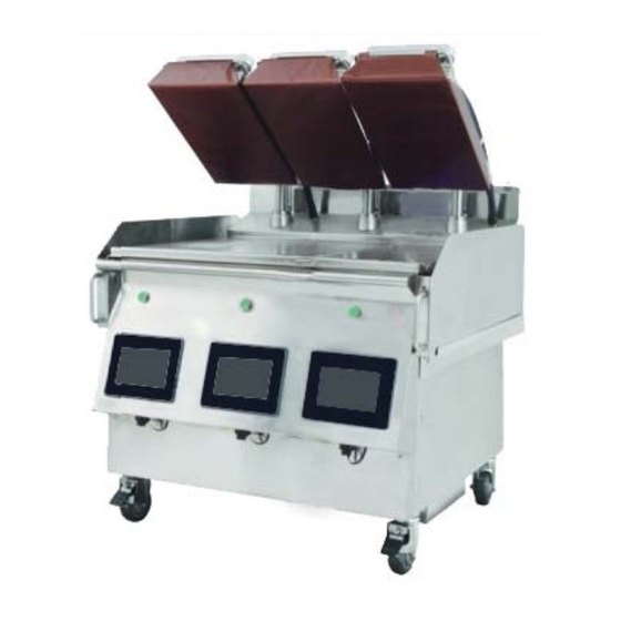
Electric/Gas Dual Side Xpress Plus Grill
Models:
XP(E/G)12
XP(E/G)24, XP(E/G)24-1(L/R)
XP(E/G)36, XP(E/G)36-1(L/R), XP(E/G)36-2(L/R)
Service Manual
Please read all sections of this manual and retain for future reference.
For your safety:
Post in a prominent location, instructions to be followed
in the event the user smell gas. This information shall be
obtained by consulting your local gas supplier.
XP(E/G)12 Shown
Original Instructions
Document: GAR_SM_4601777 Rev 1
XP(E/G)24 Shown
XP(E/G)36 Shown
Advertisement
Table of Contents

Related Manuals for Welbilt Garland XPE12

Summary of Contents for Welbilt Garland XPE12
- Page 1 Electric/Gas Dual Side Xpress Plus Grill Models: XP(E/G)12 XP(E/G)24, XP(E/G)24-1(L/R) XP(E/G)36, XP(E/G)36-1(L/R), XP(E/G)36-2(L/R) Service Manual Please read all sections of this manual and retain for future reference. For your safety: Post in a prominent location, instructions to be followed in the event the user smell gas. This information shall be obtained by consulting your local gas supplier.
- Page 2 THIS PAGE INTENTIONALLY LEFT BLANK...
-
Page 3: Definitions
Safety Notices DANGER It is the responsibility of the equipment owner to DEFINITIONS perform a Personal Protective Equipment Hazard Assessment to ensure adequate protection during DANGER maintenance procedures. Indicates a hazardous situation that, if not avoided, will result in death or serious injury. This applies to the most DANGER extreme situations. -
Page 4: Location
ELECTRICAL Warning This product contains chemicals known to the State DANGER of California to cause cancer and/or birth defects or Check all wiring connections, including factory other reproductive harm. Operation, installation, and terminals, before operation. Connections can become servicing of this product could expose you to airborne loose during shipment and installation. -
Page 5: Damage
CODE CLEARANCE Caution Warning Do not block the supply and return air vents or the air Authorized Service Representatives are obligated to space around the air vents. Keep plastic wrappings, follow industry standard safety procedures, including, paper, labels, etc. from being airborne and lodging in but not limited to, local/national regulations for the vents. - Page 6 CLEANING Warning Caution Be aware that adjacent platens may unexpectedly move at any time. “Turn Grill Off” at main switch when cleaning Ensure platens are down, in closed position, when platens as there can be an unexpected movement of the moving grill.
- Page 7 Warning Warning Remove all removable panels before lifting and This appliance must be installed with sufficient installing. ventilation to prevent the occurrence of unacceptable concentrations of substances harmful to the health of Warning personnel in the room in which it is installed. Do not contact moving parts.
-
Page 8: Table Of Contents
Table of Contents Safety Notices Definitions..............................3 Disclaimers ..............................3 Location ..............................4 Electrical ..............................4 Damage..............................5 Clearance ..............................5 Section 1 General Information Read This Manual ......................11 Unit Inspection .........................11 Model Numbers ........................11 Serial Plate Numbers ......................11 Warranty Statement ......................12 Main Features and Components ..................13 Items included with the purchase of your new grill from manufacturer: ....14 3 Platen Dimensions Specification .................15 2 Platen Dimensions Specification .................16... - Page 9 Table of Contents (continued) Section 3 Operation Sequence of Operation ....................40 easyToUCH™ Controller ....................41 Home Screen, Recipe Selector Screen & Icons ................. 41 On Screen Warnings and Alerts Messages ................. 42 Operations Overview ......................... 42 easyTOUCH™ Procedures ....................43 Start Up & Preheat ..........................43 Cook A Recipe ............................
- Page 10 Table of Contents (continued) Test Setting Mode: ......................72 Collect System Log ..........................72 Heater State ............................72 Settings Mode: .........................72 Clean Settings ............................72 Heat Errors & Limits ..........................73 Language ............................... 73 Prompts Definitions ..........................73 Protein Definitions ..........................73 Sleep Configutarion ...........................
-
Page 11: General Information
Section 1 General Information Read This Manual Model Numbers Garland Commercial Equipment developed this manual as This manual covers the following models: a reference guide for the owner/operator and installer of XP(E/G)12 this equipment. Please read this manual before installation XP(E/G)24, XP(E/G)24-1(L/R) or operation of the machine. -
Page 12: Warranty Statement
General Information Section 1 IMITED ARRANTY OMMERCIAL RODUCTS LAMSHELL RILL (U.S.A & Canada) • This Limited Warranty does not apply, and shall not cover any products IMITED ARRANTY or equipment manufactured or sold by Garland when such products or Garland Commercial Ranges Limited (“Garland”) warrants this product to be commercial equipment is installed or used in a residential or non-commercial free from defects in material and workmanship for a period of two (2) year application. -
Page 13: Main Features And Components
Section 1 General Information Main Features and Components 1. On/Off Power Switch. 10. Platen - providing double-side cooking. Each platen can be controlled separately. 2. easyToUCH™ Touch sensitive controls for easy operation. 11. Grill Plate - cooking surface with three (3) Independently 3. -
Page 14: Items Included With The Purchase Of Your New Grill From Manufacturer
General Information Section 1 Items included with the purchase of your new 3. One Grill 3 platen gas & electric included the grill from manufacturer: following list, except countries mentioned 3 PLATEN 1. Each 1 platen gas & electric grill includes the Part # Description following items;... -
Page 15: Platen Dimensions Specification
Section 1 General Information 3 Platen Dimensions Specification Dimensions: model: XP(E/G)36 PLATEN WIDTH 11.500in SHOWN WITH LEFT PLATEN REMOVED 292mm GREASE DRAWER LENGTH 5.625in 31.437in 143mm OVERALL 798mm GRILL PLATE DEPTH DEPTH 34.503in 22.000in 876mm 559mm COOK ZONE DEPTH PLATEN 19.750in 31.512in LENGTH... -
Page 16: Platen Dimensions Specification
General Information Section 1 2 Platen Dimensions Specification Dimensions: model: XP(E/G)24 PLATEN WIDTH 11.500in SHOWN WITH LEFT PLATEN REMOVED 292mm GREASE DRAWER 5.625in LENGTH 143mm OVERALL 31.437in GRILL PLATE DEPTH 798mm DEPTH 34.503in 22.000in 876mm COOK ZONE 559mm DEPTH 19.750in PLATEN 31.512in LENGTH... -
Page 17: Platen Dimensions Specification
Section 1 General Information 1 Platen Dimensions Specification Dimensions: model: XP(E/G)12 PLATEN WIDTH 11.500in 292mm SHOWN WITH PLATEN REMOVED 5.625in GREASE DRAWER OVERALL LENGTH 143mm DEPTH GRILL PLATE 31.437in 36.628in DEPTH 798mm 930mm 22.000in COOK ZONE 559mm DEPTH 31.512in PLATEN 19.750in LENGTH 800mm... -
Page 18: Electrical Input Specification - Wye (Electric Models)
General Information Section 1 Electrical Input Specification - WYE (Electric models) Document: GAR_SM_4601777 Rev 1... -
Page 19: Electrical Input Specification - Delta (Electric Models)
Section 1 General Information Electrical Input Specification - DELTA (Electric models) Document: GAR_SM_4601777 Rev 1... - Page 20 General Information Section 1 Electrical Input Specification - DELTA (Electric models), continuation Document: GAR_SM_4601777 Rev 1...
-
Page 21: Electrical Input Specification - Wye (Gas Xpg-12-Ce Models)
Section 1 General Information Electrical Input Specification - WYE (gas XPG-12-CE models) XPG-12 CE Models (gas models) XPG-12 (0L/R) CE Models (gas models) Volts Volts Total Current (A) Total Current (A) Model Model 3N (WYE) Power(kW) 3N (WYE) Power(kW) 50/60Hz 50/60Hz 220V/380V 12.6... -
Page 22: Electrical Input Specification - Wye (Gas Xpg-24 Ce Models)
General Information Section 1 Electrical Input Specification - WYE (gas XPG-24 CE models) XPG-24 CE Models (gas models) XPG-24 (0L,0R) CE Models (gas models) Volts Volts Total Current (A) Total Current (A) Model Model 3N (WYE) Power(kW) 3N (WYE) Power(kW) 50/60Hz 50/60Hz 220V/380V... -
Page 23: Electrical Input Specification - Delta (Gas Xpg-36 Models)
Section 1 General Information Electrical Input Specification - WYE (gas XPG-36 CE models) XPG-36 CE Models (gas models) XPG-36 (0L/R) CE Models (gas models) Volts Volts Total Current (A) Total Current (A) Model Model 3N (WYE) Power(kW) 3N (WYE) Power(kW) 50/60Hz 50/60Hz 220V/380V... - Page 24 General Information Section 1 Electrical Input Specification - DELTA (gas XPG-36 models), continuation XPG-36 1L Models (gas models) XPG-36 1R Models (gas models) Volts Volts Total Current (A) Total Current (A) Model Model 3 (WYE) Power(kW) 3 (WYE) Power(kW) 50/60Hz 50/60Hz 200V 20.6...
-
Page 25: Gas Input Specification
Section 1 General Information Gas Input Specification STANDARD GAS SETTINGS/SPECIFICATIONS FOR CSA APPROVED MODELS STANDARD PRESSURE SWITCH INPUT/ "TOTAL INPUT/UNIT SUPPLY MANIFOLD INJECTOR ELEVATION SPEED SETTING BURNER BTU" PRESSURE PRESSURE SIZE GAS TYPE " W.C. Colour 12in 24in 36in FEET "... -
Page 26: Gas Elevations Settings
General Information Section 1 Determining Unit Configuration for Gas Grills continuation: b. If the grill has been supplied with the following label, it has been configured for high elevation. The elevation and gas type for the unit is indicated by the punched hole in the “Appliance Set For” section. For example, on the label shown below, the unit is configured for Natural gas between 7001 and 9500 feet (2135 and 2896 meters). - Page 27 Section 1 General Information Gas Elevations Settings continuation: HIGH ELEVATION GAS SETTINGS/SPECIFICATIONS FOR CE APPROVED MODELS ELEVATION PRESSURE ¹INPUT/ ²TOTAL INPUT/UNIT SUPPLY MANIFOLD INJECTOR RANGE SPEED SWITCH SETTING BURNER PRESSURE PRESSURE SIZE GAS TYPE " W.C. Colour 12in 24in 36in METERS mbar mbar...
- Page 28 General Information Section 1 CE APPROVED CONVERSION KITS FOR ELEVATION CONVERSION KIT #4602237 FOR ALL CE APPROVED 12in UNITS THIS KIT IS USED TO CONVERT 12in CE APPROVED STANDARD SEA LEVEL UNITS TO HIGH ELEVATION UNITS. THIS KIT ONLY APPLIES TO 12in GRILLS, CONFIGURED FOR USE WITH G20 NATURAL GAS AND G31 PROPANE GAS.
-
Page 29: Conversion Labels
Section 1 General Information Conversion Labels: For CSA + CE conversion kits for elevation → For CE conversion kit G20 to G25 → For CE conversion kit for G25 to G20 → Document: GAR_SM_4601777 Rev 1... -
Page 30: Installation
Section 2 Installation STOP! - Follow the instructions below to safely and easily remove unit from packaging skid. Unit very heavy Personal Protective Equipment (PPE) required. Removing Grill From Wood Crate 3. REMOVE AND DISCARD THE TWO (2) WOOD BLOCKS LOCKING EACH OF THE FRONT CASTER. NOTE: ENSURE FRONT CASTER BRAKES ARE ON Tools required. -
Page 31: Transporting Grill To Location
Section 2 Installation Transporting Grill To Location air vents of the equipment are not blocked • The location must not be near heat-generating (broiler, Transporting your new grill to the kitchen requires the dishwashers, etc) equipment or in direct sunlight and following criteria. -
Page 32: Appliances Equipped With Casters
Installation Section 2 Casters Adjustment Procedure Ventilation Hood 1. Turn the clamshell grill Green Power Main Switch (green light off ) 25.4 1.00 Min. 2. Rear and front Casters have a threaded stem to adjust the level of the grill independent of the swiveling action 3. -
Page 33: Temporary Storage
Section 2 Installation Remove Stainless Steel Plastic Film Cover 8. Beware of the red mark in the threaded stem to Removing this film is one of the things that must be done indicated the maximum adjustment. Red mark in the once the Grill is in place. -
Page 34: Installation Store Responsibilities
Installation Section 2 must comply with CSA B149.1 and local codes where • Conduct training with your crew personnel to ensure applicable. maximum utilization of the grill. Once the installation is complete as per the procedures below, a factory • In Canada, electrical connection must comply with authorized service company MUST startup the grill applicable sections of the Canadian Electrical Code,... -
Page 35: Desi Pak" Bags From The Grill
Section 2 Installation Gas Connections, and Pipe Sizing: • The size of the gas line is very important. If the line is too small, the gas pressure at the burner manifold will be low. This will cause slow recovery and delayed ignition. The incoming gas pressure line should be a minimum of 1-1/2”. - Page 36 Installation Section 2 • Install the included quick-disconnect gas hose to the Electrical Connection inlet fitting on the underside of the grill by threading Warning brass male quick-connect coupler included with the hose onto the factory-installed elbow. Disconnect power supply before starting this procedure. FLEXIBLE GAS HOSE UNDERNEATH GRILL •...
-
Page 37: Flue Upper Rear Panel Install Instruction
Section 2 Installation Flue Upper Rear Panel Install Instruction Install flue box to the back of grill for all gas grill models only (if required). flue box assembly griddle rear backsplash Place hemmed flange of flue box over top edge of griddle rear backsplash Remove the flue assembly from the accessory box upper... - Page 38 Installation Section 2 Install Release Material Sheets 4. Gently pull the release material sheet towards (Rear Loop Option) the front platen and then In order to achieve proper cooking performance, ensure wrap the sheet around that the release material sheet is installed properly to the the front of platen and platen.
-
Page 39: Startup Procedure
Section 2 Installation Startup Procedure keep in mind this estimated time when scheduling the startup. After hours or overtime is not covered under This Garland 1, 2 & 3-platen grill comes with a factory warranty and will be billed at a charge which is the startup at no additional charge. -
Page 40: Operation
Section 3 Operation NOTE: Do not operate the unit without reading and Wrong understanding the safety requirements. Refer to the safety Platen section at the front of this manual. Position Normal Open Sequence of Operation Normal After turning the power switch to “I” or ON position, the Platen Do Not Position... -
Page 41: Easytouch™ Controller
Section 3 Operation easyToUCH™ Controller PRESS & GO – is used to initiate preheat and cook on the grill. HOME SCREEN, RECIPE SELECTOR SCREEN & ICONS The easyToUCH™ HOME and RECIPE SELECTOR screens MENUS – is used to activate, add, edit and are the most frequently used screens. -
Page 42: On Screen Warnings And Alerts Messages
Operation Section 3 ON SCREEN WARNINGS AND ALERTS MESSAGES Menus and Recipes Too Cool/Too Hot - If the grill temperature is too cool to Multiple menus can be set up, each using different set properly cook a recipe, a “Too Cool to Cook” message point and containing different or share recipes. -
Page 43: Easytouch™ Procedures
Section 3 Operation easyTOUCH™ Procedures COOK A RECIPE 1. On the RECIPE START UP & PREHEAT SELECTOR screen, 1. Switch the grill on Green light select a recipe to using the main indicates cook. that the power switch. Grill power Lay product on is “ON”... -
Page 44: Check Temperatures
Operation Section 3 CHECK TEMPERATURES CHANGE COOK TIME/GAP The temperature screen shows the actual and the set point The changes made to a recipe in this procedure in the Press temperatures at each thermocouple. & Go mode will still apply after the power is turned off. A recipe’s cook time and gap can be modified to allow for 1. -
Page 45: Create New Recipe
Section 3 Operation CREATE NEW RECIPE The easyToUCH™ screen display, layout and icons shown herein are for guidance purposes only and are not intended to be an exact representation of those displayed on the grill. 1. A recipe consists of one or more steps. A step may end with a prompt such as 1. - Page 46 Operation Section 3 Editing an Existing Recipe Pressing the list icon will display the steps in the recipe available (screen shown below). Select the step with arrows editing, then press check. Press the pencil (top right of the screen) to edit an existing recipe.
-
Page 47: Create A New Menu
Section 3 Operation CREATE A NEW MENU Menus offer the option to combine many recipes under 6. Select an image one menu screen like breakfast, lunch and other menus and press the available through the day. check-mark to continue. 7. Select a recipe(s) 1. -
Page 48: Activate Sleep Mode Manually
Operation Section 3 ACTIVATE SLEEP MODE MANUALLY SHUTDOWN Sleep mode can be selected from the RECIPE SELECTOR 1. Return to the screen to save energy during slow periods. HOME screen. Pressing the Home 1. From the RECIPE icon exits cooking SELECTOR screen, mode and turns off press... -
Page 49: Special Settings - Time & Gap Adjustment Limits
Section 3 Operation SPECIAL SETTINGS — TIME & GAP ADJUSTMENT 6. Select to save LIMITS the new settings. This setting limits the size of the cook cycle adjustments that can be made for a recipe using Change Cook Time/ Gap. For example, if the time is set to 00:10, then the COOK CYCLE ADJUSTMENT screen will only allow the operator to increase or decrease the cook time by up to ten (10) seconds. - Page 50 Operation Section 3 home page PRESSGO MENUS SETTINGS ALL RECIPES DIAGNOSTICS PressGo AM MENU Menus AM MENU BACON PM MENU MUSHROOM AM MENU LRS PM MENU SAUSAGE STEAK All Recipe QUARTER EGGS ANGUS GR CHICKEN BACON Settings FACTORY MUSHROOM PASSWORD TIME SAUSAGE DATE...
- Page 51 Section 3 Operation Diagnostic REVISION MANUFACTURE DATE INSTALL DATE SERIAL NUMBER UI HARDWARE REV. DIAGNOSTIC LOG TRACK ALL LOG INFO STATUS TIMESTAMP HEATER DUTY CYCLE 5: GRILL TYPE HEATER DUTY CYCLE 6: GRILL DESCRIPTION HEATER DUTY CYCLE 7: POWER AC LINE HEATER DUTY CYCLE 8: INPUT POWER AC PHASE A: HEATER DESIGN VOLTAGE:...
-
Page 52: Maintenance
Section 4 Maintenance Cleaning the easyToUCH™ controller Cleaning During Operation • Select lock icon on the panel, to temporarily lock 1. After each product load is removed, use a grill scraper to scrape grease on lower grill plate from front to back the touch screen for fifteen (15) seconds. -
Page 53: Daily Cleaning
Section 4 Maintenance Daily Cleaning 6. Remove the lower support rail of the grease 1. Select Clean mode for troughs from each side. each platen and, once Clean mode has been reached, turn each zone OFF and turn NOTE: Turn main switch OFF when cleaning platens. - Page 54 Maintenance Section 4 11. Apply the grill cleaner 16. Press green button to to the platen surfaces raise the right platen and starting from right turn main switch Off. platen to left platen. Pour remaining Hi-temp DO NOT SCRUB. Grill Cleaner over the bottom grill surface.
- Page 55 Section 4 Maintenance 21. Scrub outer edges of 26. Turn main switch On, right and left platens and lower the platen and turn main switch Off. turn main switch Off. Rinse inner edges of both platens. 22. Press green button to 27.
-
Page 56: Moving The Grill
Maintenance Section 4 Moving the Grill 31. Wipe lower grill with a clean sanitizer-soaked Caution grill cloth. Repeat until no visible soil remains. Ensure platens are down, in closed position, when moving grill. Avoiding procedure may cause damage or loss of calibration on the platen and potential of error message can occur. -
Page 57: Troubleshooting
Section 5 Troubleshooting Cooking Issues Problem Possible Cause Action Incorrect recipe selected Select correct recipe and retry Use cook cycle change screen to Cook time too low increase cook cycle Check that uncooked product is at Raw product too cold correct temperature (not frozen) as per Restaurant operational guideline Use cook cycle change screen to... - Page 58 Troubleshooting Section 5 Cooking Issues Problem Possible Cause Action Incorrect recipe selected Select correct recipe and retry Use cook cycle change screen to Cook time too high decrease cook cycle, as per Restaurant operational guideline. Check for correct temperature (frozen product not thawed;...
-
Page 59: Temperature Issues
Section 5 Troubleshooting Temperature Issues Problem Possible Cause Action Use temperature status screen to check Recipe set points are high zone temperatures versus set point Temperature calibration Reset off sets to default value and verify incorrect temperatures Partial load cooking driving Cook full load and recheck zone temperature on unused zone temperatures... - Page 60 Troubleshooting Section 5 Temperature Issues (continuation) Problem Possible Cause Action Use temperature status screen to check Recipe set points are low zone temperatures versus set point Kitchen ventilation aff ecting Check whether cool or high volumes of temperatures air are directed towards the grill Temperature calibration Reset off sets to default value and verify incorrect...
-
Page 61: Ui Issues
Section 5 Troubleshooting Test that contactor is disengaged by High temperature switch opening lower grate and listening for tripped contactor Open lower grate and listen for Contactor disengaged contactor disengaging Ribbon cable disengaged Reseat ribbon cable on SSRB and SIB Unable to reach or Line voltage wiring harness maintain temperature... - Page 62 Troubleshooting Section 5 Use voltmeter to confi rm main power Main power intermittent connected and live UI rebooting Check that software version is up to Wrong software version loaded date 24v power supply defective Check for blinking heartbeat LED on SIB Allow 30 seconds for USB to be Flash drive not in long enough recognized by UI...
- Page 63 Section 5 Troubleshooting Test that contactor is disengaged by High temperature switch power cycling grill and listening for tripped contactor Check limit switches, ensure wiring is Over travel switch tripped routed correctly Hood height not set or set too Go to Settings/Hood Height Calibration to check setting Check the actuator for damage, feel Platen not moving...
- Page 64 Troubleshooting Section 5 Document: GAR_SM_4601777 Rev 1...
- Page 65 Section 5 Troubleshooting Document: GAR_SM_4601777 Rev 1...
- Page 66 Troubleshooting Section 5 Document: GAR_SM_4601777 Rev 1...
- Page 67 Section 5 Troubleshooting Document: GAR_SM_4601777 Rev 1...
- Page 68 Troubleshooting Section 5 Document: GAR_SM_4601777 Rev 1...
- Page 69 Section 5 Troubleshooting Document: GAR_SM_4601777 Rev 1...
-
Page 70: Controls
Section 6 Controls Settings Mode: Factory Settings Mode: Change Password 5. Type password 1. Select “SETTINGS”. under Settings. 6. Choose the user password to change (display shown). 2. Enter password 7. Type the new (alphabet). password twice and press return. Change the Time 3. -
Page 71: Change The Date
Section 6 Controls Change the Date 20. Select the 12. Type password appropiate reset under settings. option to continue. 13. select the appropiate date (display shown). 21. This operation can not be cancel, press 14. Select check check to continue. save date. -
Page 72: Hood Height
Controls Section 6 Test Setting Mode: Hood Height 28. Type password Collect System Log under settings then select HOOD HEIGHT. 36. Type password 29. Make the under settings then appropiate select COLLECT adjustment then END SYSTEM LOG. CALIBRATION. 37. Insert USB then Thermocouple Calibration select COLLECT LOG. -
Page 73: Heat Errors & Limits
Section 6 Controls • CLEAN GRILL – this option will confi gure the lower 50. Type password grill, you can set up temperature from 150F to 450F or under settings then turn off this option by typing 32 on the numeric pad. select PROMPTS DEFINITION. -
Page 74: Instructions For Software Update
Controls Section 6 Instructions for Software Update Garland will notify FAS’s of new software drop. FAS’s are required to have clean (formatted) flashdrives with a minimum size of 8Gb. If the file received is compressed (zip), it needs to be decompressed and content (could be approx. 24 files) should be copied to a clean flashdrive. - Page 75 Section 6 Controls Scroll through Settings Press START UPDATE. to Software Update. Press START UPDATE. If search for USB unsuccessful – screen will state “Couldn’t find USB drive”. Try a different USB flashdrive and repeat number 5. If USB was found successfully, start again from number 5. The upgrade may take up to 10 minutes.
-
Page 76: Component Check Procedures
Section 7 Component Check Procedures Reading the LEDs - SIB The SIB has a number of LEDs performing different functions. For the Service Technician, the most important ones are numbers 1, 6, 7, 10, 11, and 12. If LED 1 is not blinking there may be an issue with the high voltage power or with the ribbon cable to the SSRB. -
Page 77: Reading The Leds - Sib - Diagnose Platen Errors
Section 7 Component Check Procedures Reading the LEDs - SIB - Diagnose Platen Errors Position Indicators Check the amber LEDs 6 & 7 on the SIB: LED 6 (H LED 7 (U PPER LATEN MUST BE UP AT OR ABOVE THE UPPER SWITCH LATEN MUST BE DOWN AT OR BELOW THE HOME SWITCH LATEN MUST BE BETWEEN THE HOME AND UPPER SWITCHES... -
Page 78: Reading The Leds - Sib - Platen Homing
Component Check Procedures Section 7 Reading the LEDs - SIB - Platen Homing Platen Homing Behavior At the start of the homing process, the controller fi rst determines if the platen is at the upper switch. If it is, the platen starts moving down. -
Page 79: Reading The Leds - Ssrb
Section 7 Component Check Procedures Reading the LEDs - SSRB The SSRB has one LED per heater. The LEDs blink in proportion to the power being delivered to each heater: • An LED that is always on (or nearly always) is receiving maximum power. •... -
Page 80: Replacement Of Shaft Seal & Cap O-Ring Procedure
Component Check Procedures Section 7 REPLACEMENT OF SHAFT SEAL & CAP O-RING PROCEDURE 1. Ensure that the platen is in the down position, by pressing green button. Green light 2. Turn power OFF indicates using the main that the Grill power power switch. - Page 81 Section 7 Component Check Procedures 14. Insert bushings back into the arm link and carefully thread 12. Reinstall the wear the link pin through pad (C) and tighten them and the other down using two allen side of the arm. screws (D).
-
Page 82: Actuator Replacement Procedure
Component Check Procedures Section 7 ACTUATOR REPLACEMENT PROCEDURE 1. Ensure that the 6. Remove clevis pin. platen is in the down The platen may need position, by pressing to be wedged into a green button. slightly lifted position to relieve pressure on the clevis pin enough Green light 2. - Page 83 Section 7 Component Check Procedures 16. Slide the anti-rotate 12. When replacing the into the unit from actuator ensure that the top of the slot no wires are trapped and secure back between it the to the actuator bottom frame. Do shaft.
-
Page 84: Diagrams
Section 9 Diagrams Wiring Diagram Electrical Schematic Diagrams - All WYE Models Electrical schematic diagrams are combined by zones, right, left and middle zones. For 1 platen total of one sheet, 2 platen total of two sheets, 3 platen total of three sheets. Electric General Market (WYE connection) Part# Description... -
Page 85: Platen Electric - Xpe12 Wye (4532832)
Section 9 Diagrams 1 PLATEN ELECTRIC - XPE12 WYE (4532832) Document: GAR_SM_4601777 Rev 1... - Page 86 Diagrams Section 9 1 PLATEN ELECTRIC - XPE12 WYE (4532832) - CONTINUATION Document: GAR_SM_4601777 Rev 1...
-
Page 87: Platen Electric - Xpe24 Wye (4532833)
Section 9 Diagrams 2 PLATEN ELECTRIC - XPE24 WYE (4532833) Document: GAR_SM_4601777 Rev 1... - Page 88 Diagrams Section 9 2 PLATEN ELECTRIC - XPE24 WYE (4532833) - CONTINUATION Document: GAR_SM_4601777 Rev 1...
-
Page 89: Platen Electric - Xpe36 Wye (4532834)
Section 9 Diagrams 3 PLATEN ELECTRIC - XPE36 WYE (4532834) Document: GAR_SM_4601777 Rev 1... - Page 90 Diagrams Section 9 3 PLATEN ELECTRIC - XPE36 WYE (4532834) - CONTINUATION Document: GAR_SM_4601777 Rev 1...
-
Page 91: Platen Gas - Xpg12 Wye (4532835)
Section 9 Diagrams 1 PLATEN GAS - XPG12 WYE (4532835) Document: GAR_SM_4601777 Rev 1... - Page 92 Diagrams Section 9 1 PLATEN GAS - XPG12 WYE (4532835) - CONTINUATION Document: GAR_SM_4601777 Rev 1...
-
Page 93: Platen Gas - Xpg24 Wye (4532836)
Section 9 Diagrams 2 PLATEN GAS - XPG24 WYE (4532836) Document: GAR_SM_4601777 Rev 1... - Page 94 Diagrams Section 9 2 PLATEN GAS - XPG24 WYE (4532836) - CONTINUATION Document: GAR_SM_4601777 Rev 1...
-
Page 95: Platen Gas - Xpg36 Wye (4532837)
Section 9 Diagrams 3 PLATEN GAS - XPG36 WYE (4532837) Document: GAR_SM_4601777 Rev 1... - Page 96 Diagrams Section 9 3 PLATEN GAS - XPG36 WYE (4532837) - CONTINUATION Document: GAR_SM_4601777 Rev 1...
- Page 97 Section 9 Diagrams Electrical Schematic Diagrams - All DELTA Models Electrical schematic diagrams are combined by zones, right, left and middle zones. For 1 platen total of one sheet, 2 platen total of two sheets, 3 platen total of three sheets. Electric General Market (DELTA connection) Part# Description...
- Page 98 Diagrams Section 9 Document: GAR_SM_4601777 Rev 1...
-
Page 99: Platen Electric - Xpe12 Delta (4532838)
Section 9 Diagrams 1 PLATEN ELECTRIC - XPE12 DELTA (4532838) Document: GAR_SM_4601777 Rev 1... - Page 100 Diagrams Section 9 1 PLATEN ELECTRIC - XPE12 DELTA (4532838) - CONTINUATION Document: GAR_SM_4601777 Rev 1...
-
Page 101: Platen Electric - Xpe24 Delta (4532839)
Section 9 Diagrams 2 PLATEN ELECTRIC - XPE24 DELTA (4532839) Document: GAR_SM_4601777 Rev 1... - Page 102 Diagrams Section 9 2 PLATEN ELECTRIC - XPE24 DELTA (4532839) - CONTINUATION Document: GAR_SM_4601777 Rev 1...
-
Page 103: Platen Electric - Xpe36 Delta (4532840)
Section 9 Diagrams 3 PLATEN ELECTRIC - XPE36 DELTA (4532840) Document: GAR_SM_4601777 Rev 1... - Page 104 Diagrams Section 9 3 PLATEN ELECTRIC - XPE36 DELTA (4532840) - CONTINUATION Document: GAR_SM_4601777 Rev 1...
-
Page 105: Platen Gas - Xpe12 Delta (4532841)
Section 9 Diagrams 1 PLATEN GAS - XPE12 DELTA (4532841) Document: GAR_SM_4601777 Rev 1... - Page 106 Diagrams Section 9 1 PLATEN GAS - XPG12 DELTA (4532841) - CONTINUATION Document: GAR_SM_4601777 Rev 1...
-
Page 107: Platen Gas - Xpe24 Delta (4532842)
Section 9 Diagrams 2 PLATEN GAS - XPE24 DELTA (4532842) Document: GAR_SM_4601777 Rev 1... - Page 108 Diagrams Section 9 2 PLATEN GAS - XPG24 DELTA (4532842) - CONTINUATION Document: GAR_SM_4601777 Rev 1...
-
Page 109: Platen Gas - Xpe36 Delta (4532843)
Section 9 Diagrams 3 PLATEN GAS - XPE36 DELTA (4532843) Document: GAR_SM_4601777 Rev 1... - Page 110 Diagrams Section 9 3 PLATEN GAS - XPG36 DELTA (4532843) - CONTINUATION Document: GAR_SM_4601777 Rev 1...
-
Page 111: Tools & Cleaning Supplies
Section 10 Tools & Cleaning Supplies Recommended Cleaning Supplies Grill Cleaning Pad & Handle Heat-Resistant Gloves Clean, Sanitizer-Soaked Grill Scraper Grill Squeegee Grill Cloths Note: Cleaning supplies not included with the purchase of your new grill from manufacturer. Document: GAR_SM_4601777 Rev 1... - Page 112 All of our products are backed by KitchenCare® – our aftermarket, repair, and parts service. CLEVELAND DELFIELD® FRYMASTER® KOLPAK® MANITOWOC® MERRYCHEF® CONVOTHERM® FITKITCHEN™ GARLAND LINCOLN MERCO® MULTIPLEX® ©2017 Welbilt Inc. except where explicitly stated otherwise. All rights reserved. Continuing product improvement may necessitate change of specifi cations without notice.
Need help?
Do you have a question about the Garland XPE12 and is the answer not in the manual?
Questions and answers