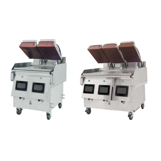
Summary of Contents for Welbilt Garland ME-1P
- Page 1 Gas/Electric Clamshell Grill M(E/G)-1P, M(E/G)-2P, M(E/G)-3PX Next Generation Grill Troubleshooting Guide Part Number: 4604223 — Rev:0...
-
Page 2: Safety Notices
Safety Notices DANGER The on-site supervisor is responsible for ensuring that DEFINITIONS operators are made aware of the inherent dangers of DANGER operating this equipment. Indicates a hazardous situation that, if not avoided, will NOTE: Proper installation, care and maintenance are result in death or serious injury. -
Page 3: Location
LOCATION ELECTRICAL Warning DANGER Two or more people or a lifting device are required to lift Check all wiring connections, including factory terminals, this appliance. before operation. Connections can become loose during shipment and installation. Warning DANGER To avoid instability the installation area must be capable of supporting the combined weight of the equipment and Do not operate any appliance with a damaged/pinched product. -
Page 4: Damage
CODE CLEARANCE Caution Warning Do not block the supply and return air vents or the air Authorized Service Representatives are obligated to follow space around the air vents. Keep plastic wrappings, industry standard safety procedures, including, but not paper, labels, etc. from being airborne and lodging in limited to, local/national regulations for disconnection the vents. - Page 5 PERSONAL PROTECTION Warning This equipment is intended for indoor use only. Do not DANGER install or operate this equipment in outdoor areas. All utilities (gas, electric, water and steam) must be OFF to all equipment and locked out of operation according to Warning OSHA approved practices during servicing.
-
Page 6: Table Of Contents
Table of Contents Safety Notices ........................1 Definitions ........................1 Disclaimers ........................1 Location ...........................2 Electrical ..........................2 Damage ...........................3 Clearance ........................3 Section 1 General Information Testing Limit switches ......................9 Check Hood Height ......................9 Testing kill switches ......................9 Motor Over current (E2 Error).................... 9 SIB Board - LED Location .................... -
Page 7: General Information
Section 1 General Information Testing Limit switches Motor Over current (E2 Error) With grill in off position Check your SIB version Revision N or higher are newest spec Revision M could cause and issue when fitted with a Norgren 1. Press green button to lower platen. Actuator. -
Page 8: Sib Board - Led Location
Section 1 Section 1 SIB Board - LED Location Color Name Meaning Green 3.3V Power Constant when power supply connected Green Motor Up Lights while platen motor moving up Blue Motor Down Lights while platen motor moving down PWR SYNCH Blinks when high voltage detected from SSRB DEBUG 1 Data Communication: On during normal operation... -
Page 9: Actuator Motion Test
Section 1 Section 1 Actuator Motion Test UI Freezing/ not booting or going slow 1. If you have software version 4.0.1 or higher then there 1. If the UI has any of the above it is recommended to install is a function called motion test. This test will drive the the Recovery software in case, there is a corrupt file (the motor up and down at various voltages to test the motor recovery process has its own instructions to follow) -
Page 10: Ui Touch Screen Calibration
Section 1 Section 1 • Power calibration 24vDC circuit dragging the voltage down. • Recipes and menus a. To isolate the faulting circuit, you can start by disconnecting each out put jumper Harness on the UI Touch screen Calibration SIB. Follow the below order and check between each disconnection. -
Page 11: Ssrb Revision Unknown
Section 1 Section 1 a. When a Triac is switched on it should flash to show it is Level Motor Not adjusting calling for heat. 1. From the +/- screen in the gap calibration screen check 5. If it still does not heat the line is within the white box and the rear sensor reeds between 160 –... -
Page 12: Baumer Sensor Faults
Section 1 Section 1 Baumer Sensor Faults Replacing a Baumer sensor 1. To check the baumer sensor the easiest method is as 1. Look at the top of the sensor and note how many threads below are visible. a. Enter the gap calibration menu. a. - Page 13 All of our products are backed by KitchenCare® – our a ermarket, repair, and parts service. CLEVELAND DELFIELD® FRYMASTER® KOLPAK® MANITOWOC® MERRYCHEF® CONVOTHERM® FITKITCHEN™ GARLAND LINCOLN MERCO® MULTIPLEX® ©2017 Welbilt Inc. except where explicitly stated otherwise. All rights reserved. Con nuing product improvement may necessitate change of specifi ca ons without no ce.


Need help?
Do you have a question about the Garland ME-1P and is the answer not in the manual?
Questions and answers