Table of Contents
Advertisement
Quick Links
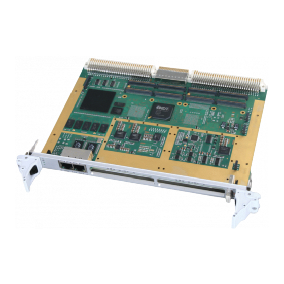
VME-PMC-
CADDY/2plus
VME-Carrier Board
for two PMC Modules
VME-PMC-CADDY/2plus (V.1915.05)
Hardware Manual
to Product: V.1915.05,
V.1915.06,
V.1915.04
VME-PMC-CADDY/2plus
Page 1 of 47
Hardware-Manual • Doc.-No.: V.1915.23 / Rev. 1.0
esd electronic system design gmbh
Vahrenwalder Str. 207 • 30165 Hannover • Germany
http://www.esd.eu
Phone: +49 (0) 511 3 72 98-0 • Fax: +49 (0) 511 3 72 98-68
Advertisement
Table of Contents

Related Manuals for ESD VME-PMCCADDY/2plus


Summary of Contents for ESD VME-PMCCADDY/2plus
- Page 1 VME-PMC-CADDY/2plus Page 1 of 47 Hardware-Manual • Doc.-No.: V.1915.23 / Rev. 1.0 esd electronic system design gmbh Vahrenwalder Str. 207 • 30165 Hannover • Germany http://www.esd.eu Phone: +49 (0) 511 3 72 98-0 • Fax: +49 (0) 511 3 72 98-68...
- Page 2 The information in this document has been carefully checked and is believed to be entirely reliable. esd makes no warranty of any kind with regard to the material in this document, and assumes no responsibility for any errors that may appear in this document. In particular descriptions and technical data specified in this document may not be constituted to be guaranteed product features in any legal sense.
- Page 3 Document- I:\Texte\Doku\MANUALS\VME\PMC-CADDY-2plus\VME-PMC-CADDY2plus_Hardware_en_10.wpd File: Date of print: 2015-09-29 VME-PMC-CADDY/2plus Rev. 3.0 PCB versions: VME-PMC-CADDY/2-CC from serial number: S/N GL000318 Changes in the chapters The changes in the document listed below affect changes in the hardware and firmware as well as changes in the description of facts only. Reversion Chapter Changes versus previous version...
- Page 4 It is the responsibility of the device's user to take care that necessary safety precautions for the device's network interface are in place.
-
Page 5: Table Of Contents
Contents 1. Overview ..............8 1.1 Block Circuit Diagram . - Page 6 9. Order Information ............46 Page 6 of 47 VME-PMC-CADDY/2plus Hardware Manual •...
- Page 7 Typographical Conventions Throughout this manual the following typographical conventions are used to distinguish technical terms. Convention Example /dev/null or <stdio.h> File and path names The following indicators are used to highlight noticeable descriptions. Attention: Warnings or cautions to tell you about operations which might have unwanted side effects.
-
Page 8: Overview
Overview 1. Overview 1.1 Block Circuit Diagram Figure 1: Block circuit diagram of VME-PMC-CADDY/2plus 1.2 General The VMEbus unit VME-PMC-CADDY/2plus is a VME64-base board which can carry up to two PMC modules of normal size. For the VMEbus connection the VME-PCI bridge Tsi148 by IDT is used. The Tsi148 is designed in a way that the board can either operate as slave or as master on the VMEbus. -
Page 9: Hardware Configurations
Overview The front panel of the VME-PMC-CADDY/2plus has two cutouts for the front panels of the PMC modules. A blank cover for unused slots is included in delivery. Example libraries for the initialization of the board in C source code for VxWorks is available for a fee on a disk. - Page 10 Overview Figure 2: Conduction cooled version VME-PMC-CADDY/2-CC Page 10 of 47 VME-PMC-CADDY/2plus Hardware Manual • Doc. No.: V.1915.23/ Rev. 1.0...
-
Page 11: Technical Data
Overview 1.4 Technical Data 1.4.1 General Technical Data IEEE 1014 / Rev. D VMEbus-Interface Master or Slave functionality Base address geographical addressing standard supervisory and non-privileged data access, Address modifier extended supervisory and non-privileged data access, short supervisory and non-privileged access - Legacy-protocols supporting the preservation of existing VME- systems VMEbus access... -
Page 12: Serial Interfaces
Overview VME-PMC-CADDY/2plus : ca. 400 g Weight VME-PMC-CADDY/2-CC (order no.: V.1915.04): 650 g VME-PMC-CADDY/2plus, VME-PMC-CADDY/2plus-T: VMEbus P1, P2: 5 V ± 5% / typical 2 A current consumption 3.3 V not in use (see chapter. 1.4.4) +12V ±5% (only to PMC slots) Power supply voltage -12V ±5% (only to PMC slots) -
Page 13: Ethernet Interfaces
Overview 1.4.3 Ethernet Interfaces The Ethernet interfaces are not equipped in the VME-PMC-CADDY/2-CC version. 2x Gigabit Ethernet (VME-PMC-CADDY/2plus and Number VME-PMC-CADDY/2plus-T only) Standard IEEE802.3, 10 BASE-T, 100BASE-TX, 1000BASE-T Bit rate 10 Mbit/s, 100 Mbit/s, 1000 Mbit/s Controller MPC8349 Physical interface Twisted Pair (IEEE802.3) Galvanic isolation via transformer... -
Page 14: Pmc-Slots
Overview 1.4.4 PMC-Slots PMC-Standard IEEE Std 1386-2001, IEEE Std 1386.1-2001 Equipment two single-size modules VME-PCI-Bridge Tsi148 I/O-Signals Standard: according to VITA 35 (P4V2-64ac, P4V0-46), i.e. to VMEbus P2 PMC slot 1 (J14) completely to P2 row a and c, and P0 PMC slot 2 (J24) completely to VMEbus connector P0 3.3 V Note:... -
Page 15: Software
Overview In the standard placement of the VME-PMC-CADDY/2plus and the VME-PMC-CADDY/2plus-T the 3.3 V power supply voltage for board and PMC card is generated onboard. 3.3 V: max. 1.5 A current consumption per PMC slot 3.3 V AUX: for both PMC slots together max. -
Page 16: Front Panel And Leds
Front Panel and LEDs 2. Front Panel and LEDs 2.1 VME-PMC-CADDY/2plus and VME-PMC-CADDY/2plus-T Figure 3: Front of the VME-PMC-CADDY/2plus Page 16 of 47 VME-PMC-CADDY/2plus Hardware Manual • Doc. No.: V.1915.23/ Rev. 1.0... -
Page 17: Led Display
Front Panel and LEDs 2.1.1 LED Display Meaning (LED on) Labelling on Name Colour front panel BUSY green Access from VMEbus to VME-PMC-CADDY/2plus VME-PMC-CADDY/2plus triggers an interrupt on the green VMEbus FAIL VME-PMC-CADDY/2plus triggers FAIL on VMEbus VME-PMC-CADDY/2plus triggers Bus-Error on BERR VMEbus Table 5: Indication of the LEDs... -
Page 18: Vme-Pmc-Caddy/2-Cc
Front Panel and LEDs 2.2 VME-PMC-CADDY/2-CC Figure 4: Front of the conduction cooled version VME-PMC-CADDY/2-CC Note: In the VME-PMC-CADDY/2-CC version the LEDs, the Ethernet ports 1 and 2 and the serial interface connector X1940 are not equipped. The signals of the serial interface are available via P0. Page 18 of 47 VME-PMC-CADDY/2plus Hardware Manual •... -
Page 19: Reset Button
Front Panel and LEDs 2.3 Reset Button The reset button can be enabled by pushing with a non-conducting bar-shaped object (max. 1.5 mm diameter).It triggers a local reset on the VME-PMC-CADDY/2plus or VME-PMC-CADDY/2-CC and consequently also on the PMC modules. Furthermore a reset is triggered on the VMEbus. VME-PMC-CADDY/2plus Page 19 of 47 Hardware-Manual •... -
Page 20: Pcb View With Coding Switches And Connectors
Configuration 3. PCB View with Coding Switches and Connectors Figure 5: Connector position top layer VME-PMC-CADDY/2plus Note: In the VME-PMC-CADDY/2-CC version the Ethernet ports 1 and 2 and the serial interface connector X1940 are not equipped. The signals of the serial interface are available via P0. Page 20 of 47 VME-PMC-CADDY/2plus Hardware Manual •... - Page 21 Configuration Figure 6: Coding switch and connector position bottom layer VME-PMC-CADDY/2plus In the default version of the VME-PMC-CADDY/2plus and VME-CADDY/2plus-T the SMD resistors RX130-RX135 are not equipped. See chapter “General technical Data” on page 15 for information about the power supply voltages. In the default version of the VME-PMC-CADDY/2-CC the SMD resistors RX130-RX135 are equipped instead of the resistors RX2530-RX2535.
-
Page 22: Default Setting Of The Coding Switches
Configuration 3.1 Default Setting of the Coding Switches The default settings of the board as delivered is shown in the following table. The coding switches are positioned on the bottom layer. The position of the coding switch can be taken from figure 6. -
Page 23: Vmebus Configuration (Sw600)
Configuration 3.2 VMEbus Configuration (SW600) Figure 7: Coding Switch SW600 The position of the coding switch on the VME-PMC-CADDY/2plus can be taken from figure 6. 3.2.1 Overview Coding switch Default Bit name Function contact setting SFAILEN Control Bit Reset Value SFAILAI Control Bit Auto Clear VMEbus Power Up Options Auto Slot ID Enable... -
Page 24: Vmebus System Controller Setup
Configuration 3.2.2 VMEbus System Controller Setup This bits define how and whether the VME-PMC-CADDY/2plus is activated as VMEbus system controller. Coding switch- Coding switch contact 2 contact 1 Function SCONEN# SCONDIS# Auto SCON: automatic activation of the system controller (depending of signal VBG3IN#)) System controller activated System controller deactivated not allowed... -
Page 25: Vmebus Power-Up-Options
Configuration 3.2.3 VMEbus Power-Up-Options After a reset the Tundra PCI/X-to-VMEbus-bridge TS148 evaluates different PCI/X-bus and VMEbus signals to enable or disable various functions. For the VMEbus the data signals VD[0] to VD[3] are evaluated. Coding switch VMEbus Power-up option Description contact data bit VD[0]... -
Page 26: Pmc Slot Configuration (Sw800)
Configuration 3.3 PMC Slot Configuration (SW800) Figure 8: Coding switch SW800 (default setting) The position of the coding switch on the VME-PMC-CADDY/2plus can be taken from figure 6. Coding switch- Name Description Default contact reserved for future applications; P-PUPEN always set to “OFF” Clock rate of the PCI-Bus of the PMC modules: P-M66EN... -
Page 27: Connect Special Vme-Signals To Pmc-I/O Signals (Sw100)
Configuration 3.4 Connect Special VME-Signals to PMC-I/O Signals (SW100) Figure 9: Coding switch SW100 (default setting) The position of the coding switch on the VME-PMC-CADDY/2plus can be taken from figure 6. Via coding switch SW100 the VMEbus signals V-SERCLK and V-SERDAT can be connected to the PMC I/O-Signals I/O204 and I/O104 as described in detail in the following table: Coding Coding... -
Page 28: Hardware Installation
Installation 4. Hardware Installation Read the safety instructions at the beginning of this document carefully, before you start with the hardware installation! DANGER Hazardous Voltage - Risk of electric shock due to unintentional contact with uninsulated live parts with high voltages inside of the system into which theVME- PMC-CADDY/2plus is to be integrated. -
Page 29: Address Assignment Of Vme-Pmc-Caddy/2Plus
Address Assignment 5. Address Assignment of VME-PMC-CADDY/2plus Address range Assignment 0x00000000 ... 0x03ffffff DDR2 RAM (72 bit data width) 0x80000000 ... 0x8fffffff PCI Memory Space (prefetchable) 0x90000000 ... 0x9fffffff PCI Memory Space 0xe0000000 ... 0xe00fffff CPU IMMR 0xe2000000 ... 0xe20fffff PCI IO Space 0xffc00000 ... -
Page 30: Bootloader
The VME-PMC-CADDY/2plus module uses the opensource bootloader „Das U-Boot“. The U-Boot sourcecode is published in terms of the GNU public license (GPL). Please see esd's „3rd party licensor notice“ document that is part of the product's documentation for the full license text. You can contact esd for a copy of the full bootloader sourcecode for the VME-PMC-CADDY/2plus. -
Page 31: Booting Vxworks
Bootloader 6.3 Booting VxWorks Here are step-by-step instructions for booting VxWorks at the serial console. The tftp command requires a correct U-Boot network configuration. That means the bootloader environment variables ipaddr and serverip must be set up according to your network. When any of the following steps fail, do not proceed! 1. -
Page 32: Flash Update
0xFFF00000. Please check that you are using the correct bootloader image that suits to your board! The bootloader update process is very delicate. Any mistake may result in a board that is not usable anymore and which must be shipped back to be reprogrammed by esd using a JTAG debugger. -
Page 33: Booting Linux
Bootloader 6.5 Booting Linux Here is an example for step-by-step instructions for booting Linux at the serial console. The tftp command requires a correct U-Boot network configuration. That means the bootloader environment variables must be set up according to your network. When any of the following steps fail, do not proceed! The first three steps are only for VME-PMC-CPU/2 modules. - Page 34 Bootloader 11. Set the name of the kernel image: 12. Set the address, the kernel image shall be send to: 13. Set address of the FDT-file: 14. Set path to the FDT-file: 15. Prepare booting with: 15. Start booting with: Page 34 of 47 VME-PMC-CADDY/2plus Hardware Manual •...
-
Page 35: Connector Assignment
Connector Assignment 7. Connector Assignment 7.1 Serial Interfaces RS-232 (V.1915.05, V.1915.06 only)) The connector is not equipped in the VME-PMC-CADDY/2-CC. ® Device connector: har-link female multipoint connector 10-pin, Harting Nr.: 27211218000 Pin Position: Pin Assignment: Signal Row 1 Row 2 TXS1 RXS1 RTSS1#... -
Page 36: Adapter Cable "Vme-Pmc-Cpu/Cable
Connector Assignment 7.1.1 Adapter Cable “VME-PMC-CPU/Cable” An adapter cable from 10-pin har-link to 9-pin DSUB (order No.: V.1917.25). is available for the connection of the serial interface 1. Pin Position DSUB9: Pin Assignment: DSUB9 har-link Signal direction * Signal TXS1 RXS1 CTSS1# RTSS1#... -
Page 37: Adapter Cable "Vme-Pmc-Cpu/Cable-Y
Connector Assignment 7.1.2 Adapter Cable “VME-PMC-CPU/Cable-Y” An adapter cable with Y-junction from 10-pin har-link to 2x 9-pin DSUB (order No.: V.1917.26). is available for the connection of the serial interfaces 1 and 2. Pin Position in the DSUB9 Socket: Pin Assignment: DSUB9 “1”... -
Page 38: Ethernet Interface (V.1915.05, V.1915.06 Only)
Connector Assignment 7.2 Ethernet Interface (V.1915.05, V.1915.06 only) The connector is not equipped in the VME-PMC-CADDY/2-CC version. The Ethernet interfaces are equipped with 8-pin RJ45-sockets (8P8C) according to TIA-568A/B Pin Position: Cut-out for fastening lever Pin Assignment: Signal MDI0+ (TP0+) MDI0- (TP0-) MDI1+... -
Page 39: Vmebus P1
Connector Assignment 7.3 VMEbus P1 Row z Row a Row b Row c Row d BBSY* BCLR* ACFAIL* BG0IN* BG0OUT* BG1IN* BG1OUT* BG2IN* BG2OUT* GAP* SYSCLK BG3IN* SYSFAIL* GA0* BG3OUT* BERR* GA1* DS1* BR0* SYSRESET* +3.3V DS0* BR1* LWORD* GA2* WRITE* BR2* +3.3V... -
Page 40: Standard Assignment Of I/O-Signals
Connector Assignment 7.4 Standard Assignment of I/O-Signals 7.4.1 Standard Assignment VMEbus P2 (According to VITA 35, P4 V2-64ac) In the standard assignment the I/O signals of the PMC slot 1 (J14) are connected to the rows a+c. Row z Row a Row b Row c Row d... -
Page 41: Standard Assignment Of Transfer Module With P2 Row A And C Signals
Connector Assignment 7.4.2 Standard Assignment of Transfer Module with P2 Row a and c Signals The table below shows the assignment of a 64-pole transfer module connected to P2 connector. The 64 contacts of the module are connected to the signals of the rows a and c of the connector P2. Thus all I/O-contacts of the PMC slot 1 (J14) are accessible via the transfer module. -
Page 42: Standard Assignment Vmebus P0
Connector Assignment 7.4.3 Standard Assignment VMEbus P0 Pin Row f Row e Row d Row c Row b Row a RXS2 TXS2 RXS1 TXS1 I/O201 I/O202 I/O203 I/O204 I/O205 I/O206 I/O207 I/O208 I/O209 I/O210 I/O211 I/O212 I/O213 I/O214 I/O215 I/O216 I/O217 I/O218 I/O219... -
Page 43: Standard Assignment Of The I/O Connector J14 At Pmc Slot 1
Connector Assignment 7.4.4 Standard Assignment of the I/O Connector J14 at PMC Slot 1 Signal Signal Pin No Name to P2-Pin Name to P2-Pin I/O101 I/O102 I/O103 I/O104 I/O105 I/O106 I/O107 I/O108 I/O109 I/O110 I/O111 I/O112 I/O113 I/O114 I/O115 I/O116 I/O117 I/O118 I/O119... -
Page 44: Standard Assignment Of The I/O Connector J24 At Pmc Slot 2
Connector Assignment 7.4.5 Standard Assignment of the I/O Connector J24 at PMC Slot 2 Signal Signal Pin No. Name to P0-Pin Name to P0-Pin I/O201 I/O202 I/O203 I/O204 I/O205 I/O206 I/O207 I/O208 I/O209 I/O210 I/O211 I/O212 I/O213 I/O214 I/O215 I/O216 I/O217 I/O218 I/O219... -
Page 45: References
References 8. References Tsi148™PCI/X-to-VME Bus Bridge User Manual, Tundra Semiconductor Corporation, referenced document version: 80A3020_MA001_10, April 2008 The manual can be downloaded from the website of IDT Integrated Device Technology: http://www.idt.com VME-PMC-CADDY/2plus Page 45 of 47 Hardware-Manual • Doc.-No.: V.1915.23 / Rev. 1.0... - Page 46 PDF Manuals Manuals are available in English and usually in German as well. For availability of English manuals see the following table. Please download the manuals as PDF documents from our esd website www.esd.eu for free. Page 46 of 47 VME-PMC-CADDY/2plus Hardware Manual •...
- Page 47 Hardware manual in English V.1915.23 Table 14: Available manuals Printed Manuals If you need a printout of the manual additionally, please contact our sales team: sales@esd.eu for a quotation. Printed manuals may be ordered for a fee. VME-PMC-CADDY/2plus Page 47 of 47...
Need help?
Do you have a question about the VME-PMCCADDY/2plus and is the answer not in the manual?
Questions and answers