Table of Contents
Advertisement
Quick Links
PCIe-XPIMC-Carrier
XMC/PMC/PIM Carriers for PCIe
Hardware Manual
to Product V.2100.01, V.2100.02
PCIe-XPIMC-Carrier
Hardware Manual • Doc. No.: V.2100.21 / Rev. 1.2
Page 1 of 27
esd electronic system design gmbh
Vahrenwalder Str. 207 • 30165 Hannover • Germany
http://www.esd.eu
Phone: +49 (0) 511 3 72 98-0 • Fax: +49 (0) 511 3 72 98-68
Advertisement
Table of Contents

Related Manuals for ESD PCIe-XPIMC-Carrier


Summary of Contents for ESD PCIe-XPIMC-Carrier
- Page 1 PCIe-XPIMC-Carrier Hardware Manual • Doc. No.: V.2100.21 / Rev. 1.2 Page 1 of 27 esd electronic system design gmbh Vahrenwalder Str. 207 • 30165 Hannover • Germany http://www.esd.eu Phone: +49 (0) 511 3 72 98-0 • Fax: +49 (0) 511 3 72 98-68...
- Page 2 The information in this document has been carefully checked and is believed to be entirely reliable. esd makes no warranty of any kind with regard to the material in this document, and assumes no responsibility for any errors that may appear in this document. In particular descriptions and technical data specified in this document may not be constituted to be guaranteed product features in any legal sense.
- Page 3 Document file: I:\Texte\Doku\MANUALS\PMC\PCIe-XPIMC-Carrier\PCIe-XPIMC-Carrier_Hardware_en_12.odt Date of print: 2012-11-26 Document type DOC0800 number: Hardware version: 1.0 Document History The changes in the document listed below affect changes in the hardware as well as changes in the description of the facts, only. Revision...
- Page 4 ● The PCIe-XPIMC-Carrier may become warm during normal use. Always allow adequate ventilation around the PCIe- XPIMC-Carrier and use care when handling. ● Do not operate the PCIe-XPIMC-Carrier adjacent to heat sources and do not expose it to unnecessary thermal radiation. Ensure an ambient temperature as specified in the technical data.
-
Page 5: Table Of Contents
X3 – PIM Test Signals......................22 X4 – Special P0 Signals.......................23 Option: X5A/B – Aux Power (12V) ..................24 Declaration of Conformity......................25 9. References..........................26 Order Information........................27 PCIe-XPIMC-Carrier Hardware Manual • Doc. No.: V.2100.21 / Rev. 1.2 Page 5 of 27... -
Page 6: Overview
(option) Figure 1: Block circuit diagram The PCIe-XPIMC-Carrier is a PCIe 1x board that can carry a single PMC or alternatively a XMC module. The PMCs PCI interface is connected to the boards PCIe card edge interface through a single lane (1x) PCI/PCIe bridge. When using a XMC module its first PCIe lane is connected to the card edge connector. -
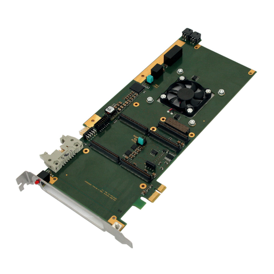
Page 7: Pcb View With Connectors
PCB View with Connectors 2. PCB View with Connectors 2.1 Normal Version Figure 2: PCB top view (normal version) PCIe-XPIMC-Carrier Hardware Manual • Doc. No.: V.2100.21 / Rev. 1.2 Page 7 of 27... -
Page 8: Component Placement Of Reverse Version
The position of the connectors J0, J1, J2, J4A, J4B, J15 and X300 and the pin position of • these connectors is described in Figure: 4 (page 9). Page 8 of 27 Hardware Manual • Doc. No.: V.2100.21 / Rev. 1.2 PCIe-XPIMC-Carrier... - Page 9 PCB View with Connectors Figure 4: Position of connectors and pins of PCIe-XPIMC(reverse)-Carrier (detail) PCIe-XPIMC-Carrier Hardware Manual • Doc. No.: V.2100.21 / Rev. 1.2 Page 9 of 27...
-
Page 10: Hardware Configuration
XMC site PCIe/PCI bridge 1 This option is only available on the Carriers's hardware revision 1.0. Beginning with the revision 1.1, the jumper only has two contacts. Page 10 of 27 Hardware Manual • Doc. No.: V.2100.21 / Rev. 1.2 PCIe-XPIMC-Carrier... -
Page 11: Hardware Installation
It is strongly recommended to install additional mounting brackets due to the high mass of of a PCIe-XPIMC-Carrier with installed PIM and PMC/XMC modules. Care must be taken especially during transport of the PC with installed PCI-XPIMC- Carriers. -
Page 12: Leds
Fan or fan or temperature error condition. The Error Temperature LED1 LED behavior is uneffected by PROT Error jumper status. Table 1: Description of LED Page 12 of 27 Hardware Manual • Doc. No.: V.2100.21 / Rev. 1.2 PCIe-XPIMC-Carrier... -
Page 13: Technical Data
0°C .. +50°C ambient temperature range Humidity max. 90%, non-condensing Dimensions ~98 mm x ~250 mm Weight 155 g Table 2: General data of the module PCIe-XPIMC-Carrier Hardware Manual • Doc. No.: V.2100.21 / Rev. 1.2 Page 13 of 27... -
Page 14: Pci/Pcie Interface
Table 4: Data of PMC interface 6.4 PIM Number Standard acc. to Vita 36d0.1 PIM card size one single-size module Connectors J0, J4b Table 5: Data of PIM interface Page 14 of 27 Hardware Manual • Doc. No.: V.2100.21 / Rev. 1.2 PCIe-XPIMC-Carrier... -
Page 15: Power Supply, Fan And Monitoring
A power cycle of the carrier is required to return to normal operation. In case of a fan or temperature error the red LED is turn on. PCIe-XPIMC-Carrier Hardware Manual • Doc. No.: V.2100.21 / Rev. 1.2 Page 15 of 27... -
Page 16: Connector Assignments
PM-T7 +3.3V PM-T8 n.c. -12V n.c. Note: SCL/SDA are connected to any I²C capable component on the carrier. This includes the thermal sensors (2 x DS1631A). Page 16 of 27 Hardware Manual • Doc. No.: V.2100.21 / Rev. 1.2 PCIe-XPIMC-Carrier... -
Page 17: J1 - Pmc/Xmc Connector
+3.3 V via 3.3 kΩ +3.3 V via 3.3 kΩ PCI.PAR +3.3V P-AD15 P-AD12 P-AD11 P-AD9 PCI.C/BE(0)# P-AD6 P-AD5 P-AD4 +3.3V P-AD3 P-AD2 P-AD1 P-AD0 +3.3 V via 3.3 kΩ PCIe-XPIMC-Carrier Hardware Manual • Doc. No.: V.2100.21 / Rev. 1.2 Page 17 of 27... -
Page 18: J2 - Pmc/Xmc Connector
PCI.STOP# PCI.PERR# +3.3V PCI.SERR# PCI.C/BE1# P-AD14 P-AD13 PCI.M66EN P-AD10 P-AD8 +3.3V P-AD7 PCI.REQ1# +3.3V PCI.GNT1# n.c. n.c. n.c. n.c. +3.3 V via 3.3 kΩ +3.3V n.c. Page 18 of 27 Hardware Manual • Doc. No.: V.2100.21 / Rev. 1.2 PCIe-XPIMC-Carrier... -
Page 19: Connectors
The signal assignments of the I/O-connectors J4A and J4B are identical. The signal pins of the connectors J4A and J4B are 1:1 connected internally. So signals are only passed through. PCIe-XPIMC-Carrier Hardware Manual • Doc. No.: V.2100.21 / Rev. 1.2 Page 19 of 27... -
Page 20: Connector
3.3V AUX n.c. n.c. +3.3V n.c. n.c. n.c. n.c. n.c. n.c. n.c. n.c. n.c. n.c. n.c. n.c. n.c. PEX.RCLK0.P PEX.RCLK0.N n.c. n.c. n.c. n.c. Page 20 of 27 Hardware Manual • Doc. No.: V.2100.21 / Rev. 1.2 PCIe-XPIMC-Carrier... -
Page 21: X2 - Pim Jtag Connector
Pin Position (connector view): Pin: 13 Pin Assignment: Signal Signal +3.3V PIM-TMS PIM-TCK PIM-TDO PIM-TDI n.c. PIM-TRST# Note: All JTAG signals are directly routed to the PIM J0 connector. PCIe-XPIMC-Carrier Hardware Manual • Doc. No.: V.2100.21 / Rev. 1.2 Page 21 of 27... -
Page 22: X3 - Pim Test Signals
2 PCB side Pin Assignment: Signal Signal PM-T1 PM-T2 PM-T3 PM-T4 PM-T5 PM-T6 PM-T7 PM-T8 +3.3V Note: All test signals are directly routed to the PIM J0 connector. Page 22 of 27 Hardware Manual • Doc. No.: V.2100.21 / Rev. 1.2 PCIe-XPIMC-Carrier... -
Page 23: X4 - Special P0 Signals
Note 2: All signal pairs are terminated by a series network (100R + 1nF) Note 3: All test signals are directly routed to the PIM J0 connector PCIe-XPIMC-Carrier Hardware Manual • Doc. No.: V.2100.21 / Rev. 1.2 Page 23 of 27... -
Page 24: Option: X5A/B - Aux Power (12V)
X5A/B are are optional and not installed per default. Per default the 12 V power supply voltage is supplied via the card edge connector. When X5A/B are used to supply the board the +12V rail on the card edge must be disconnected. Please contact esd for instructions. Page 24 of 27 Hardware Manual •... -
Page 25: Declaration Of Conformity
Declaration of Conformity 8. Declaration of Conformity PCIe-XPIMC-Carrier Hardware Manual • Doc. No.: V.2100.21 / Rev. 1.2 Page 25 of 27... -
Page 26: References
[2] PCI local bus specification, Rev. 3.0 [3] PMC – IEEE 1386 [4] XMC specification (Vita 42.0) [5] PIM specification (Vita 36 – 199X) [6] PCIe electromechanical specification, Rev. 2.0 Page 26 of 27 Hardware Manual • Doc. No.: V.2100.21 / Rev. 1.2 PCIe-XPIMC-Carrier... -
Page 27: Order Information
Table 6: Order information PDF Manuals Manuals are available in English and usually in German as well. For availability of English manuals see table below. Please download the manuals as PDF documents from our esd website www.esd.eu for free. Manuals Order No.
Need help?
Do you have a question about the PCIe-XPIMC-Carrier and is the answer not in the manual?
Questions and answers