
Subscribe to Our Youtube Channel
Related Manuals for Vdwall LVP909


Summary of Contents for Vdwall LVP909
-
Page 1: Table Of Contents
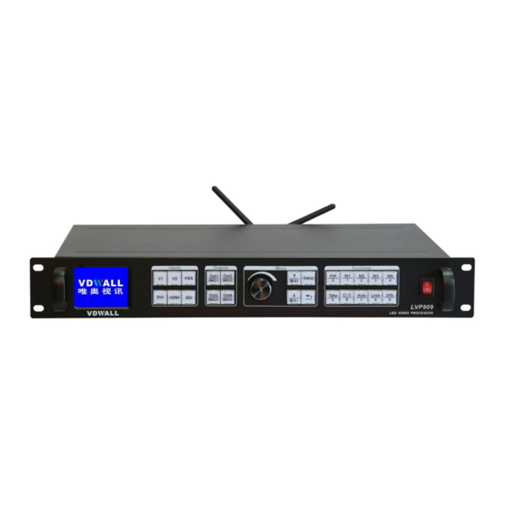
LVP909 operation instruction Contents: 1………………………………………………….Signal switch buttons 2………………………………………………….Output channel selection buttons 3………………………………………………….User setup buttons 4………………………………………………….Function buttons 5………………………………………………….Power switch and socket 6………………………………………………….Software control port 7………………………………………………….Output ports 8………………………………………………….Input ports 9………………………………………………….Sending card slot... -
Page 2: Signal Switch Buttons
14…………………………………………………Setting output width and height (App 2 3 4) 15…………………………………………………Setting output width and height (App 5 6) 16…………………………………………………Configuring input source for App5 6 17…………………………………………………Setting PIP (POP) 1. Signal switch buttons 1.1. LVP909 has 6 channels of input port: V1 V2 VGA DVI HDMI SDI;... -
Page 3: Output Channel Selection Buttons
LVP909 outputs HDMI video source, of course you have connected HDMI source to the input port; 2. Output channel selection buttons 2.1. LVP909 has 4 output ports Out1 Out2 Out3 Out4, when configure output port parameters in user menu press relative button to select output port then configure it;... -
Page 4: User Setup Buttons
image layer parameters in user menu press relative button to select image layer then configure it 3. User setup buttons 3.1. Knob OK: when configuring parameters value rotate it to change or increase and decrease parameter value; 3.2. Brt+: after entering user setup menu, press it to select next setup option when not in setup configuration state press it to increase brightness);... -
Page 5: Function Buttons
4. Function buttons 4.1. PIP: PIP (picture in picture) function switch; 4.2. M1 M2 M3 M4: memory buttons, LVP909 can save 4 modes in advanced (when in application mode 1 save 4 mode for PIP, when in another mode can save 4 modes for output port parameters);... -
Page 6: Power Switch And Socket
4.5. Auto: VGA signal automatically adjust button, when input VGA source to LVP909 and the video on LED screen not in the correct location and has some display problem, press the button to adjust VGA input source let it OK;... -
Page 7: Output Ports
6.3. Wifi antenna: LVP909F has Wifi control function, first install APP on mobile phone then open wifi of phone to find LVP909 wifi then connect it, after connecting you can open APP on phono to control LVP909F by Wifi function;... -
Page 8: Input Ports
VGA input port; 8. Input ports 8.1. LVP909 has 6 channels of input port SDI DVI HDMI VGA connect relative format video source to relative input port, for example Laptop VGA to connect VGA port;... - Page 9 9.1. LVP909 can put two common sending cards inside, normally common sending card only has two RJ45 ports; 10. Setting language 10.1. Press power switch to open processor, then you can see the interface as below; 输入: 输入状态: 1366x768_60 -------------------------------------------------------------------- 输出位置大小:...
- Page 10 6. 语言/Language -------------------------------------------------------------------- 6.1. 语言/Language English 11. Setting output resolution 11.1. Press Setup button to enter user setup menu, press Brt+ button to select 1. Output CFG, press OK to enter configuration menu; Setup -------------------------------------------------------------------- >> 1.Output CFG >> 2.Output Image >>...
- Page 11 12.2. Press Brt- button to select 1.2 App Mode, rotate OK to select the proper application mode you need, after selectin resolution press Brt- button to select 1.3 Setup press OK to confirm (LVP909 has 6 application modes); Output CFG -------------------------------------------------------------------- 1.1 Resolution...
- Page 12 12.3. Application mode 1: Out1 = Out2 = 1 program (switcher) Out3 = No Output Out4 = Pre + Sync. Monitor 12.4. Application mode 2: Out1 + Out2 = 2 program (2 Mosaic) Out3 = No output Out4 = Pre + Sync. Monitor...
- Page 13 12.5. Application mode 3: Out1 + Out2 + Out3 = 3 program (3 Mosaic) Out4 = Sync. Monitor 12.6. Application mode 4:...
- Page 14 Out1 + Out2 + Out3 + Out4 = 4 program (4 Mosaic) No Monitor Output 12.7. Application mode 5 Out1 = Out2 = 1 program (4 image) Out3 = No Output Out4 = Sync. Monitor...
- Page 15 12.8. Application mode 6 Out1 = Out2 = 1 program (3 image) Out3 = No Output Out4 = Input Sync. Monitor...
- Page 16 13. Setting output width and height (App 1) 13.1. Press Setup button to enter user setup menu, press Brt- button to select 2. Output Image, press OK to enter output image setup menu; Setup -------------------------------------------------------------------- >> 1.Output CFG >> 2.Output Image >>...
- Page 17 14. Setting output width and height (App 2 3 4) 14.1. Press Setup button to enter user setup menu, press Brt- button to select 2. Output Image, press OK to enter output image setup menu; 14.2. Application mode 2 3 and 4 especially used for splicing large LED screen, so in the menu we need to configure whole LED screen resolution, unit LED screen resolution and input H and Y start;...
- Page 18 14.9. After configuring Out1 press Out2 button to select Out2 then configure it, press Out 3 or Out4 button can select them then configure them; 15. Setting output width and height (App 5 6) 15.1. After LVP909 configuring App M5, then you can see the interface as below; Image_1 Source: Image_1 Status:...
- Page 19 15.2. Press Setup button to enter user setup menu, press Brt- button to select 2. Output Image, press OK to enter output image setup menu; 15.3. Press Brt+ or Brt- button to select setup option, rotate OK to change parameters, press OK to save; 2.
- Page 20 16.2. Press Brt+ or Brt- button to select setup option, rotate OK to select input source, press OK to save; 3. Image Source AppM5 -------------------------------------------------------------------- 3.1 Image_1 Source DVI HDMI 3.2 Image_2 Source DVI HDMI 3.3 Image_3 Source DVI HDMI 3.4 Image_4 Source DVI HDMI 17.Setting PIP (POP)
- Page 21 D. PIP AppM1 -------------------------------------------------------------------- D.1 Image_1 Source DVI HDMI -------------------------------------------------------------------- D.2 Image_2 Source DVI HDMI -------------------------------------------------------------------- >> D.3 Output Image 17.3. Select setup option D.3 Output Image, press OK to enter setup menu, press Brt+ or Brt- to select setup option, rotate OK to configure parameter value, press OK to save;...
- Page 22 Out1 to select main widow, press Out2 to select PIP window,...
Need help?
Do you have a question about the LVP909 and is the answer not in the manual?
Questions and answers