
Related Manuals for Pulsar RED POWER EN54-7A28


Summary of Contents for Pulsar RED POWER EN54-7A28
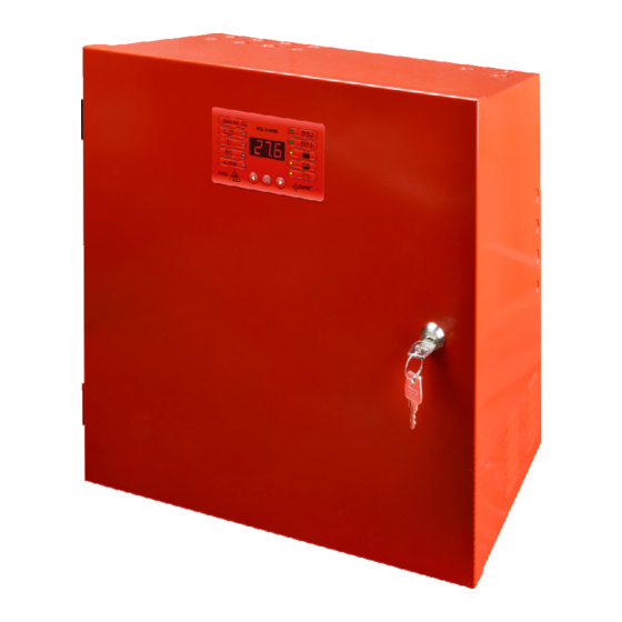
- Page 1 EN54-7A28 v.1.0 EN54 27,6V/7A/2x28Ah power supply for fire alarm systems EN** Edition: 1 from 28.11.2013 Supersedes the edition: ---------------- LED Version...
-
Page 2: Table Of Contents
RED POWER www.pulsar.pl EN54-7A28 TABLE OF CONTENTS 1. PSU FEATURES: ..........................4 2. PACKAGE CONTENTS........................5 3. FUNCTIONAL REQUIREMENTS OF THE PSU................6 4. TECHNICAL DESCRIPTION......................7 4.1. G ..............................7 ENERAL DESCRIPTION 4.2. B ................................7 LOCK DIAGRAM 4.3. D ..................8 ESCRIPTION OF COMPONENTS AND POWER SUPPLY TERMINALS 5. - Page 3 RED POWER www.pulsar.pl EN54-7A28 7. RESERVE POWER SUPPLY CIRCUIT..................30 7.1. B ..............................30 ATTERY DETECTION 7.2. P ................30 ROTECTION AGAINST SHORT CIRCUIT OF THE BATTERY TERMINALS 7.3. P ....................30 ROTECTION AGAINST REVERSE BATTERY CONNECTION 7.4. D UVP......................30 EEP DISCHARGE BATTERY PROTECTION 7.5.
-
Page 4: Psu Features
RED POWER www.pulsar.pl EN54-7A28 1. PSU features: • In accordance with standards: EN 54-4, • remote battery test (additional modules required) • cooperation with optional EN54-LB4 or EN54-LB8 EN12101-10 • 27,6V DC/ 7A uninterruptible power supply fuse modules • battery housing for two 28Ah/12V batteries •... -
Page 5: Package Contents
RED POWER www.pulsar.pl EN54-7A28 2. Package contents. • Power Supply Unit • User manual • • Red mounting spacers – 4 pieces • Red, metal mounting brackets for hanging the power supply – 4 pieces • M8x16 mounting screws – 4 pieces •... -
Page 6: Functional Requirements Of The Psu
RED POWER www.pulsar.pl EN54-7A28 3. Functional requirements of the PSU. The buffer power supply for fire alarm systems has been designed in accordance with the following standards: - EN 54-4:2001 and / A2:2007 Fire detection and fire alarm systems. - EN 12101-10:2007 Smoke and heat control systems. -
Page 7: Technical Description
RED POWER www.pulsar.pl EN54-7A28 4. Technical description. 4.1. General description. The buffer power supply has been designed for an uninterrupted supply of fire alarm systems, smoke and heat control systems, fire protection equipment and fire automatics requiring stabilized voltage of 24V DC (± 15%). -
Page 8: Description Of Components And Power Supply Terminals
RED POWER www.pulsar.pl EN54-7A28 4.3. Description of components and power supply terminals. Table 1. Components of the Power supply PCB (Printed Circuit Board) (Fig. 2). Component Description PANEL – optical indication connector (see section 6.3.4) BUZZER – acoustic indication (see section 6.5) jumper –... - Page 9 RED POWER www.pulsar.pl EN54-7A28 Table 2. Components of the PCB of the EMC filter (Fig. 3). Element nr Opis fuse in the power supply circuit 230V, T6,3A / 250V MAINS L-N power supply connector 230V AC, PE protective connector for connecting the PSU.
- Page 10 RED POWER www.pulsar.pl EN54-7A28 Table 3. Elements of the PSU (Fig. 4). Component Description Isolation transformer Printed Circuit Board (see Table 1, Fig. 2) Battery temperature sensor. Space to install an additional module: “INTR”, “INTE”, “INTW” Place to install the EN54-LB4 or EN54-LB8 fuse module TAMPER;...
-
Page 11: Installation
RED POWER www.pulsar.pl EN54-7A28 5. Installation. 5.1. Requirements. The PSU is to be mounted by a qualified installer, holding relevant permits and licenses (applicable and required for a given country) for 230V/AC in and low-voltage installations. As the power supply is designed for a continuous operation and is not equipped with a power- switch, therefore, an appropriate overload protection in the power supply circuit should be provided. -
Page 12: Installation Procedure
RED POWER www.pulsar.pl EN54-7A28 5.2. Installation procedure. CAUTION! Before installation, cut off the voltage in the 230V power-supply circuit. To switch power off, use an external switch, in which the distance between the contacts of all poles in the disconnection state is not less than 3mm 1. -
Page 13: Functions
RED POWER www.pulsar.pl EN54-7A28 6. Functions. 6.1. Control Panel. The PSU features a panel with buttons and LED display, enabling reading of all the available electrical parameters. The panel buttons are used to select and confirm the parameters, which should be displayed. -
Page 14: Main Menu
RED POWER www.pulsar.pl EN54-7A28 6.2. Main menu. The PSU is equipped with a menu, which allows to preview the current electrical parameters. Diagram explaining the menu structure is presented below Fig. 8. Menu of the display. Table 7. The description of display symbols. -
Page 15: Voltage Indicator „Uo1", „Uo2
RED POWER www.pulsar.pl EN54-7A28 6.2.1. Voltage indicator „Uo1”, „Uo2” Voltage indicator displays the measured output voltage at the AUX1 and AUX2 outputs. If the voltage drops below 26V or exceeds 29.2V, the PSU will indicate a failure. The resolution of voltage measurement is 0.1V and should be treated with caution. If a greater accuracy is required, use a multimeter. -
Page 16: Current Failures „Flc
RED POWER www.pulsar.pl EN54-7A28 - press „OK” button - number 1, indicating the number of failure in the memory (the highest priority), will be displayed. Then, after one second, failure code will be displayed automatically - press „OK” button - the number 2, denoting the next number of failure in the memory, will be displayed. Then, after one second, the next failure code will be displayed automatically - if the memory has more failures, pressing the "OK"... -
Page 17: List Of Failure Codes And Information Messages
RED POWER www.pulsar.pl EN54-7A28 - press „OK” button - the number 2, denoting the next number of failure in the memory, will be displayed. Then, after one second, the next failure code will be displayed automatically - if the memory has more failures, pressing the "OK" button will result in displaying Subsequent codes - The „- - -„... - Page 18 RED POWER www.pulsar.pl EN54-7A28 temperature ALARM - Overloaded batteries. - Faulty batteries. APS FLT, Section 7.1 No battery! - Disconnected batteries ALARM APS FLT, Section 7 Faulty battery! - Deeply discharged batteries , voltage below 20V ALARM High resistance Section 7.6...
-
Page 19: Psu Configuration
RED POWER www.pulsar.pl EN54-7A28 6.3. PSU configuration. The PSU is equipped with a configuration menu that allows to configure the settings by changing or the activation of some of its parameters. The figure illustrating the configuration menu structure is shown below. -
Page 20: Performing Battery Test „Tst
RED POWER www.pulsar.pl EN54-7A28 Table 10. Description of symbols. Additional Symbol Description information Battery test – „tSt” Sections On – battery test activation 6.3.1 and 7.5 EXTo output – „Eto” Section On – relay on 6.3.2 OFF – relay off EPS output delay –... -
Page 21: Exto Output On/Off„Eto
RED POWER www.pulsar.pl EN54-7A28 6.3.2. EXTo output ON/OFF„Eto” Controlled relay output EXTo (external output) does not depend on the operation of the power supply unit and can be switched independently of its work. The EXTo output can be used for switching between controlling, resetting and supplying inputs/outputs in low-voltage electrical circuits. -
Page 22: Acoustic Indication On/Off „Buz
RED POWER www.pulsar.pl EN54-7A28 - use the „<” or „>” buttons to display the „EPS” parameter - press „OK” - The current status will be displayed - use the „<” or „>” buttons in order to set the delay time 0.10 - 10s (factory setting) -
Page 23: Led Display Dimmer „Dis
RED POWER www.pulsar.pl EN54-7A28 - use the „<” or „>” buttons in order to set the status On – acoustic indication on OFF – acoustic indication off - confirm by pressing "OK" - in order to return to the main menu, simultaneously press the „<,>” rightmost and leftmost buttons 6.3.5. -
Page 24: Setting The Communication Address Adr" Applies To Cooperation With Powersecurity
RED POWER www.pulsar.pl EN54-7A28 6.3.6. Setting the communication address Adr” applies to cooperation with PowerSecurity. All power supplies are factory-set to address 1. All the parameters responsible for communication between the PSU and the computer, namely the address, parity and speed should have the same settings for both the PSU and the PowerSecurity program. -
Page 25: Setting The Parity Of The Transmission "Trp" Applies To Cooperation With Powersecurity
RED POWER www.pulsar.pl EN54-7A28 - use the „<” or „>” buttons to display the „trS” parameter - press „OK” - The information about the transmission speed will be displayed - use the „<” or „>” buttons in order to set the required transmission speed, - 9.6k... -
Page 26: Technical Outputs
RED POWER www.pulsar.pl EN54-7A28 6.4. Technical outputs. The PSU is equipped with galvanically isolated indication outputs changing status after a specified event: • EPS FLT – output indicating AC power loss. The output indicates 230V AC power loss. Under normal status – with the 230V AC supply on, the output is closed. -
Page 27: Indication Of The Enclosure Opening - Tamper
RED POWER www.pulsar.pl EN54-7A28 The connection of external devices to the EXT IN input is shown in the electrical diagram below. OC outputs (open collector) or relay outputs can be used as the source of the signal. Fig. 12. Examples of connections. -
Page 28: Increasing The Number Of Outputs With Optional En54-Lb4 Or En54-Lb8 Fuse Modules
RED POWER www.pulsar.pl EN54-7A28 6.7. Increasing the number of outputs with optional EN54-LB4 or EN54-LB8 fuse modules. The PSU has two independently protected outputs for connecting the AUX1 and AUX2 receivers. If the power supply unit is connected with more receivers, then it is recommended to secure each of them with independent fuse. -
Page 29: Psu Overload
RED POWER www.pulsar.pl EN54-7A28 6.9. PSU overload. The PSU is fitted with the LED OVL (overload) on the PCB and indicator on the LED panel, informing about output overload. If the nominal current of the PSU is exceeded, the led turns on and the... -
Page 30: Reserve Power Supply Circuit
RED POWER www.pulsar.pl EN54-7A28 7. Reserve power supply circuit. The PSU is fitted with intelligent circuits: battery charging circuit with the function of the accelerated charging and battery control, which main task is to monitor the condition of the batteries and the connections in the circuit. -
Page 31: Measurement Of The Resistance Of The Battery Circuit
RED POWER www.pulsar.pl EN54-7A28 7.6. Measurement of the resistance of the battery circuit. The PSU is checking the resistance in the battery circuit. During the measurement, the PSU driver takes into account the key parameters in the circuit, and once the limit value of 300m ohms is exceeded, a failure is indicated . -
Page 32: Remote Monitoring (Options: Wi-Fi, Ethernet, Rs485, Usb)
RED POWER www.pulsar.pl EN54-7A28 8. Remote monitoring (options: Wi-Fi, Ethernet, RS485, USB). The PSU has been adjusted to operate in a system that requires a remote control of the parameters in a monitoring centre. Transmitting data concerning PSU status is possible due to an additional, external communication module responsible for communication in Wi-Fi, Ethernet or RS485 standard. -
Page 33: The Wi-Fi Wireless Communication
RED POWER www.pulsar.pl EN54-7A28 The RS485-WiFi „INTRE” interface is a device used to convert signals between the RS485 bus and the Wi- Fi network. For proper operation, the unit requires an external power supply in the range of 10÷30V DC e.g. drawn from a PSU of the EN54 series. -
Page 34: Rs485 Network Communication
RED POWER www.pulsar.pl EN54-7A28 The RS485-WiFi „INTRW” interface is a device used to convert signals between the RS485 bus and the WiFi network. For proper operation, the unit requires an external power supply in the range of 10÷30V DC e.g. -
Page 35: Powersecurity" Program
RED POWER www.pulsar.pl EN54-7A28 8.5. „PowerSecurity” program. The ”Power Security” program is available on www.pulsar.pl Its detailed description can be found in the manual. „Power Security” is a free computer program developed to view and analyze the information sent from the PSU installation spots. -
Page 36: Technical Parameters
RED POWER www.pulsar.pl EN54-7A28 9. Technical parameters. Electrical parameters (Table 12). Mechanical parameters (Table 13). Safety of use (Table 14). Recommended types and sections of installation cables (Table 15) Table 12. Electrical parameters. Functional class PN-EN 12101-10:2007 Mains supply 230V AC (-15%/+10%) - Page 37 RED POWER www.pulsar.pl EN54-7A28 T 6,3A / 250V MAINS F 10A / 250V F 8A / 250V AUX1 F 8A / 250V AUX2 - USB-TTL „INTU” interface; USB-TTL communication - RS485 „INTR” interface; RS485 communication - USB-RS485 „INTUR” interface; USB-RS485 communication - Ethernet „INTE”...
-
Page 38: Technical Inspections And Maintenance
RED POWER www.pulsar.pl EN54-7A28 10. Technical inspections and maintenance. Technical inspections and maintenance can be performed after disconnecting the power supply from the power network. The PSU does not require any specific maintenance, however, its interior should be cleaned with compressed air if it is used in dusty conditions. - Page 39 RED POWER www.pulsar.pl EN54-7A28...
- Page 40 GENERAL WARRANTY CONDITIONS 1. Pulsar K. Bogusz Sp.j. (manufacturer) grants a five-year quality warranty for the equipment, starting from the production date. 2. The warranty includes free-of-charge repair or replacement with an appropriate equivalent (selected by the manufacturer) if the malfunction is due to the manufacturer.
Need help?
Do you have a question about the RED POWER EN54-7A28 and is the answer not in the manual?
Questions and answers