
Related Manuals for Pulsar EN54-3A28LCD


Summary of Contents for Pulsar EN54-3A28LCD
- Page 1 EN54-3A28LCD v.1.1 EN54 27,6V/3A/2x28Ah/LCD power supply for fire alarm systems EN** Edition: 4 from 11.01.2016 Supersedes the edition: 3 from 26.08.2014 LCD Version...
-
Page 2: Table Of Contents
RED POWER www.pulsar.pl EN54-3A28LCD TABLE OF CONTENTS 1. PSU FEATURES: ............................ 4 2. PACKAGE CONTENTS........................5 3. FUNCTIONAL REQUIREMENTS OF THE PSU................6 4. TECHNICAL DESCRIPTION......................7 4.1. G ................................ 7 ENERAL DESCRIPTION 4.2. B ................................. 7 LOCK DIAGRAM 4.3. - Page 3 RED POWER www.pulsar.pl EN54-3A28LCD 8. RESERVE POWER SUPPLY CIRCUIT................... 38 8.1. B ................................. 38 ATTERY DETECTION 8.2. P ................38 ROTECTION AGAINST SHORT CIRCUIT OF THE BATTERY TERMINALS 8.3. P ....................38 ROTECTION AGAINST REVERSE BATTERY CONNECTION 8.4.
-
Page 4: Psu Features
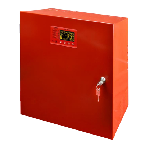
RED POWER www.pulsar.pl EN54-3A28LCD 1. PSU features: In accordance with standards: EN 54-4, cooperation with optional EN54-LB4 or EN54-LB8 EN12101-10 fuse modules 27,6V DC/ 3A uninterruptible power supply optical indication of PSU overload OVL battery housing for two 28Ah/12V batteries ... -
Page 5: Package Contents
RED POWER www.pulsar.pl EN54-3A28LCD 2. Package contents. Power Supply Unit User manual Red mounting spacers – 4 pieces Red, metal mounting brackets for hanging the power supply – 4 pieces M8x16 mounting screws – 4 pieces ... -
Page 6: Functional Requirements Of The Psu
RED POWER www.pulsar.pl EN54-3A28LCD 3. Functional requirements of the PSU. The buffer power supply for fire alarm systems has been designed in accordance with the following standards: - EN 54-4:2001 and / A2:2007 Fire detection and fire alarm systems. - EN 12101-10:2007 Smoke and heat control systems. -
Page 7: Technical Description
RED POWER www.pulsar.pl EN54-3A28LCD 4. Technical description. 4.1. General description. The buffer power supply has been designed for an uninterrupted supply of fire alarm systems, smoke and heat control systems, fire protection equipment and fire automatics requiring stabilized voltage of 24V DC (± 15%). -
Page 8: Description Of Components And Power Supply Terminals
RED POWER www.pulsar.pl EN54-3A28LCD 4.3. Description of components and power supply terminals. Table 1. Components of the Power supply PCB (Fig. 2). Comp onent Description PANEL – optical indication connector BUZZER – acoustic indication (section 7.2.2) jumper – polarization of the EXTi circuit (section 6.6) - Page 9 RED POWER www.pulsar.pl EN54-3A28LCD Table 2. Components of the PCB of the EMC filter (Fig. 3). Element Description fuse in the power supply circuit 230V, T3,15A / 250V MAINS L-N power supply connector 230V AC, PE protective connector Connector– for connecting the PSU.
- Page 10 RED POWER www.pulsar.pl EN54-3A28LCD Table 3. Elements of the PSU (see Fig. 4). Component Description Isolation transformer Printed Circuit Board (see Table 1, Fig. 2) Battery temperature sensor. Space to install an additional module: “INTR”, “INTE”, “INTW”, Place to install the EN54-LB4 or EN54-LB8 fuse module TAMPER;...
-
Page 11: Installation
RED POWER www.pulsar.pl EN54-3A28LCD 5. Installation. 5.1. Requirements. The PSU is to be mounted by a qualified installer, holding relevant permits and licenses (applicable and required for a given country) for 230V/AC in and low-voltage installations. As the power supply is designed for a continuous operation and is not equipped with a power- switch, therefore, an appropriate overload protection in the power supply circuit should be provided. - Page 12 RED POWER www.pulsar.pl EN54-3A28LCD 1. Mount the PSU in a selected location with use of special metal expansion bolts. Do not use PVC dowels. 2. Connect the power cables (230V AC) to L-N terminals of the PSU. Connect the ground wire to the terminal marked with grounding symbol: PE.
-
Page 13: Functions
RED POWER www.pulsar.pl EN54-3A28LCD 6. Functions. 6.1. Control Panel. The PSU features a panel with buttons and LCD display, enabling reading of all the available electrical parameters. The panel buttons are used to select and confirm the parameters, which should be displayed. -
Page 14: First Run Of The Psu - Language Selection Screen
RED POWER www.pulsar.pl EN54-3A28LCD 6.2. First run of the PSU – language selection screen. During the first run of the PSU, language selection screen will be displayed. Use the „<” or „>” buttons to select the available languages. After selecting the appropriate language, confirm by pressing the "SET"... -
Page 15: Information Displayed On The Lcd Panel
RED POWER www.pulsar.pl EN54-3A28LCD 6.4. Information displayed on the LCD panel. 6.4.1. Preview menu. Pressing the „ESC” button at the bottom of the display starts the preview menu, allowing to choose one of the four available PSU screens. Use the „<” or „>” buttons to choose a proper screen and press the „SET” button to confirm. -
Page 16: Lcd Screen - Current Parameters
RED POWER www.pulsar.pl EN54-3A28LCD 6.4.2. LCD screen – current parameters To set the screen, press the „ESC” button, use the „<” or „>” buttons to choose the icon and press the „SET” button to confirm. The screen displays electrical parameters and the status of the technical outputs during operation. -
Page 17: Lcd Screen - Current Failures
RED POWER www.pulsar.pl EN54-3A28LCD 6.4.3. LCD screen – current failures In case of abnormal electrical parameters during the operation, the PSU will indicate a failure by displaying a message on the LCD, turning on the red LED ALARM on the panel, activating acoustic indication (if enabled) and changing the status of a dedicated technical output. - Page 18 RED POWER www.pulsar.pl EN54-3A28LCD Fig. 14. Screen of the history of PSU’s parameters. In order to change the displayed parameter, highlight its name by pressing the „SET” button and use the „<” or „>” buttons to choose the requested parameter. Pressing the „SET” button again will highlight the time range of the chart, which also can be changed with the „<”...
-
Page 19: Lcd Screen - History Of Events
RED POWER www.pulsar.pl EN54-3A28LCD 6.4.5. LCD screen – history of events In case of abnormal electrical parameters during the operation, the PSU will indicate a failure by displaying a message on the LCD, periodically turning on and off the LCD backlight, turning on the red LED ALARM on the panel, activating acoustic indication (if enabled) and changing the status of a dedicated technical outputs. -
Page 20: List Of Failure Codes And Information Messages
RED POWER www.pulsar.pl EN54-3A28LCD 6.4.6. List of failure codes and information messages. The PSU indicates the operation status with the appropriate code. The codes are divided into two groups,marked with the initial letters "F" or "I”. The codes beginning with the letter "F" indicate a failure. The codes that begin with the letter "I" indicate the correct operation of the PSU or repaired fault, involving, for example, fuse replacement: "I03 - BAT fuse replaced”. -
Page 21: Technical Outputs
RED POWER www.pulsar.pl EN54-3A28LCD Table 10. List of PSU message codes. Message Description code Power supply start-up AC power back AUX fuse replaced AUX2 fuse replaced BAT fuse replaced Battery connected Battery OK Battery temperature OK AC voltage OK EXTo output ON EXTo output OFF Battery test –... -
Page 22: Input Of Collective Failure Exti
RED POWER www.pulsar.pl EN54-3A28LCD The technical outputs have been made with galvanic isolation between the PSU’s systems and the attached devices. Fig. 17. Electrical diagram of technical outputs. ALARM - technical output of collective failure indication. Output indicating collective failure. In the case of failure at any EPS, APS, or PSU output or at the EXTi input, the collective failure signal ALARM will be generated. -
Page 23: Indication Of The Enclosure Opening - Tamper
RED POWER www.pulsar.pl EN54-3A28LCD Fig. 20. Example of a connection with the fuse module EN54-LB8. 6.7. Indication of the enclosure opening - TAMPER. The PSU is fitted with the microswitch tamper indicating enclosure opening. The tamper cable is not connected to the terminal in the factory settings. In order to activate tamper, remove the jumper from tamper terminal (Fig. -
Page 24: Overvoltage Protection Of The Psu Output Ovp
RED POWER www.pulsar.pl EN54-3A28LCD When installing the fuse module in the PSU, power supply current consumption, used for the calculation of standby time (see section 8.8), should be taken into account. Depending on the version, fuse module allows to connect 4 or 8 receivers to the PSU. Output state is indicated by green LEDs. -
Page 25: Psu Settings
RED POWER www.pulsar.pl EN54-3A28LCD 7. PSU settings. The PSU has a configuration menu, allowing to configure the PSU settings by changing or activating certain parameters. To enter the setting mode, press the "SET" button from the main screen’s level. Fig. 22. PSU settings screen. -
Page 26: Changing The Password
RED POWER www.pulsar.pl EN54-3A28LCD - confirm by pressing the "SET" button - use the „<” or „>” buttons to enter the first digit - confirm by pressing the "SET" button - use the „<” or „>” buttons to enter the second digit - confirm by pressing the "SET"... -
Page 27: Keyboard Lock
RED POWER www.pulsar.pl EN54-3A28LCD 7.1.5. Keyboard lock. When entering passwords, it is possible to choose whether the buttons on the front panel of the PSU's „Keyboard password” should be locked. It is enabled by option. - use the „<” or „>” buttons to display the... -
Page 28: Psu
RED POWER www.pulsar.pl EN54-3A28LCD 7.2. PSU. The “PSU” menu is only available after entering the correct service password. Selecting the “PSU” in the settings menu will display another menu, allowing full configuration of the PSU; battery test ON/OFF, acoustic indication ON/OFF, EXTo output ON/OFF, setting the delay time for EPS output, setting the communication parameters. -
Page 29: Acoustic Indication On/Off
RED POWER www.pulsar.pl EN54-3A28LCD ”WAIT” - When performing the test, the LCD will display the message. 7.2.2. Acoustic indication ON/OFF Emergency situations that may arise during the operation of the PSU are indicated acoustically. The frequency and number of signals depend on the type of event (see section 6.4.6.). -
Page 30: Exto Output On/Off
RED POWER www.pulsar.pl EN54-3A28LCD 7.2.3. EXTo output ON/OFF Controlled relay output EXTo (external output) does not depend on the operation of the power supply unit and can be switched independently of its work. The EXTo output can be used for switching between controlling, resetting and supplying inputs/outputs in low-voltage electrical circuits. -
Page 31: Setting The Communication Address Applies To Cooperation With Powersecurity
RED POWER www.pulsar.pl EN54-3A28LCD - press the „SET” button, the prompt will appear at the end of the line - use the „<” or „>” buttons to set the delay time: - 10s - 1min - 10min - 30min - confirm by pressing the „SET” button 7.2.5. -
Page 32: Setting The Transmission Parameters Applies To Cooperation With Powersecurity
RED POWER www.pulsar.pl EN54-3A28LCD 7.2.6. Setting the transmission parameters applies to cooperation with PowerSecurity. All the parameters responsible for communication between the PSU and the computer, namely the address, parity and speed should have the same settings for both the PSU and the PowerSecurity program. -
Page 33: Control Panel
RED POWER www.pulsar.pl EN54-3A28LCD 7.3. Control panel. The menu is only available after entering the correct user’s or service password. The „control panel” menu enables configuration of the settings directly related to the user interface. It is possible to set the display language, date, time, intensity of the backlight and blinking light indicating failure. -
Page 34: Setting The Display Language
RED POWER www.pulsar.pl EN54-3A28LCD 7.3.1. Setting the display language One of the functions of the control panel menu is the possibility to select language. Display language can be set according to personal preference. - use the „<” or „>” buttons to display the... -
Page 35: Setting The Time
RED POWER www.pulsar.pl EN54-3A28LCD 7.3.3. Setting the time The „Time” menu in the „Control panel” menu enables setting the correct time, according to which error messages and operation history will be saved. Built-in real time clock does not take into account leap year and the changes resulting from the switch between summer and winter time. -
Page 36: Contrast Setting
RED POWER www.pulsar.pl EN54-3A28LCD - press the „SET” button, the prompt will appear at the end of the line - use the „<” or „>” buttons to set the required brightness - confirm by pressing the „SET” button 7.3.5. Contrast setting The „Contrast”... - Page 37 RED POWER www.pulsar.pl EN54-3A28LCD - press the „SET” button, the prompt will appear at the end of the line - use the „<” or „>” buttons to select – blinking light indicating failure ON – blinking light indicating failure OFF...
-
Page 38: Reserve Power Supply Circuit
RED POWER www.pulsar.pl EN54-3A28LCD 8. Reserve power supply circuit. The PSU is fitted with intelligent circuits: battery charging circuit with the function of the accelerated charging and battery control, which main task is to monitor the condition of the batteries and the connections in the circuit. -
Page 39: Measurement Of The Resistance Of The Battery Circuit
RED POWER www.pulsar.pl EN54-3A28LCD The battery test will also be automatically locked when the PSU is in the operating mode, in which the battery test is impossible. Such condition occurs, for example, during battery assisted operation or when the power supply is overloaded. -
Page 40: Remote Monitoring (Options: Wi-Fi, Ethernet, Rs485, Usb)
RED POWER www.pulsar.pl EN54-3A28LCD 9. Remote monitoring (options: Wi-Fi, Ethernet, RS485, USB). The PSU has been adjusted to operate in a system that requires a remote control of the parameters in a monitoring centre. Transmitting data concerning PSU status is possible due to an additional, external communication module responsible for communication in Wi-Fi, Ethernet or RS485 standard. -
Page 41: The Wi-Fi Wireless Communication
RED POWER www.pulsar.pl EN54-3A28LCD The RS485-ETHERNET „INTRE” interface is a device used to convert signals between the RS485 bus and the Ethernet network. For proper operation, the unit requires an external power supply in the range of 10÷30V DC e.g. drawn from a PSU of the EN54 series. The physical connection of the interface takes place under galvanic isolation. -
Page 42: Rs485 Network Communication
RED POWER www.pulsar.pl EN54-3A28LCD The RS485-WiFi „INTRW” interface is a device used to convert signals between the RS485 bus and the WiFi network. For proper operation, the unit requires an external power supply in the range of 10÷30V DC e.g. -
Page 43: Powersecurity" Program
RED POWER www.pulsar.pl EN54-3A28LCD 9.5. „PowerSecurity” program. The ”Power Security” program is available on www.pulsar.pl Its detailed description can be found in the manual. „Power Security” is a free computer program developed to view and analyze the information sent from the PSU installation spots. -
Page 44: Technical Parameters
RED POWER www.pulsar.pl EN54-3A28LCD 10. Technical parameters. Electrical parameters (Table 15). Mechanical parameters (Table 16). Safety of use (Table 17). Operation parameters (Table 18) Recommended types and sections of installation cables (Table 19) Table 15. Electrical parameters. Functional class PN-EN 12101-10:2007... - Page 45 RED POWER www.pulsar.pl EN54-3A28LCD 2 levels of password protected access operation memory of the PSU – 6144 values failure memo - 2048 events real time clock with battery backup - piezoelectric indicator ~75dB /0,3m, switched from the LCD...
- Page 46 RED POWER www.pulsar.pl EN54-3A28LCD Table 17. Safety of use. Protection class PN-EN 60950-1:2007 I (first) Protection grade PN-EN 60529: 2003 IP42 Insulation electrical strength: - between input (network) circuit and the output circuits of the PSU (I/P-O/P) 3000 V/AC min.
-
Page 47: Technical Inspections And Maintenance
RED POWER www.pulsar.pl EN54-3A28LCD 11. Technical inspections and maintenance. Technical inspections and maintenance can be performed after disconnecting the power supply from the power network. The PSU does not require any specific maintenance, however, its interior should be cleaned with compressed air if it is used in dusty conditions.
Need help?
Do you have a question about the EN54-3A28LCD and is the answer not in the manual?
Questions and answers