
Subscribe to Our Youtube Channel
Related Manuals for FLIR Raymarine p70Rs


Summary of Contents for FLIR Raymarine p70Rs
- Page 1 p70s / p70Rs Pilot Controller INSTALLATION & OPERATION INSTRUCTIONS English (EN) Date: 05-2016 Document number: 81365-2 © 2016 Raymarine UK Limited...
- Page 3 Gear Up, Marine Shield, Seahawk, Autohelm, Automagic, and Visionality are registered or claimed trademarks of Raymarine Belgium. FLIR, DownVision, SideVision, Dragonfly, Quantum, Instalert, Infrared Everywhere, and The World’s Sixth Sense are registered or claimed trademarks of FLIR Systems, Inc. All other trademarks, trade names, or company names referenced herein are used for identification only and are the property of their respective owners.
-
Page 5: Table Of Contents
Contents Chapter 1 Important information......7 Chapter 7 Commissioning - Evolution autopilot system ..........41 TFT Displays ............... 8 7.1 Evolution autopilot installation ....... 42 Water ingress .............. 8 7.2 Autopilot commissioning — main differences Disclaimer ..............8 between Evolution and SPX systems ......42 EMC installation guidelines .......... - Page 6 12.3 User preferences menu ........92 12.4 System set-up menu........... 94 12.5 Diagnostics menu..........95 Chapter 13 Maintenance ........97 13.1 Routine equipment checks........98 13.2 Product cleaning ..........98 13.3 Cleaning the display screen ........ 99 13.4 Cleaning the display case ........99 13.5 Cleaning the sun cover ........
-
Page 7: Chapter 1 Important Information
Chapter 1: Important information Warning: Product grounding Before applying power to this product, Warning: Autopilot system ensure it has been correctly grounded, in Installation accordance with the instructions provided. As correct performance of the vessel’s steering is critical for safety, we Warning: Positive ground systems STRONGLY RECOMMEND that Do not connect this unit to a system which... -
Page 8: Tft Displays
TFT Displays prevent erratic behavior and data loss which can occur if the engine start does not have a separate The colors of the display may seem to vary when battery. viewed against a colored background or in colored • Raymarine specified cables are used. light. -
Page 9: Warranty Registration
Warranty registration To register your Raymarine product ownership, please visit www.raymarine.com and register online. It is important that you register your product to receive full warranty benefits. Your unit package includes a bar code label indicating the serial number of the unit. You will need this serial number when registering your product online. - Page 10 p70s / p70Rs...
-
Page 11: Chapter 2 Document And Product Information
Chapter 2: Document and product information Chapter contents • 2.1 Document information on page 12 • 2.2 Product overview on page 13 Document and product information... -
Page 12: Document Information
2.1 Document information Document illustrations Your product may differ slightly from that shown This document contains important information in the illustrations in this document, depending on related to the installation of your Raymarine product. product variant and date of manufacture. The document includes information to help you: All images are provided for illustration purposes only. -
Page 13: Product Overview
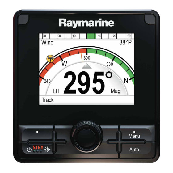
2.2 Product overview The p70s and p70Rs are SeaTalk pilot controllers. D13016-2 1. p70s 8 button (sail) Pilot Controller 2. p70Rs Rotary (power) Pilot Controller The unit has the following features: • 3.45” high brightness color LCD with wide viewing angles •... - Page 14 p70s / p70Rs...
-
Page 15: Chapter 3 Planning The Installation
Chapter 3: Planning the installation Chapter contents • 3.1 Installation checklist on page 16 • 3.2 Parts Supplied on page 16 • 3.3 Compatible autopilot systems on page 17 • 3.4 Software updates on page 17 • 3.5 Tools on page 18 •... -
Page 16: Installation Checklist
3.1 Installation checklist 3.2 Parts Supplied Installation includes the following activities: The following parts are supplied with your product. Installation Task Plan your system. Obtain all required equipment and tools. Site all equipment. Route all cables. Drill cable and mounting holes. Make all connections into equipment. -
Page 17: Compatible Autopilot Systems
3.3 Compatible autopilot systems 3.4 Software updates Your product is compatible with the Raymarine The software running on the product can be updated. Autopilot systems shown below. • Raymarine periodically releases software updates to improve product performance and add new Product Description Connection... -
Page 18: Tools
3.5 Tools 3.6 System protocols Your product can be connected to various products Tools required for installation and systems to share information and so improve the functionality of the overall system. These connections may be made using a number of different protocols. -
Page 19: Warnings And Cautions
3.7 Warnings and cautions 3.8 General location requirements Important considerations when choosing a suitable Important: Before proceeding, ensure that you location for your product. have read and understood the warnings and cautions provided in the Chapter 1 Important This product is suitable for mounting above or below information section of this document. -
Page 20: Unit Dimensions
3.9 Unit dimensions Site Requirements 17.8 mm (0.7 in) 14.05 mm 110 mm (4.33 in) 90 mm (0.55 in) 29.8 mm (3.54 in) (1.17 in) D12103-2 > 0.8m (2ft 6in) D12031-2 Site requirements for the p70s / p70Rs Pilot controller are as follows: •... -
Page 21: Chapter 4 Cables And Connections
Chapter 4: Cables and connections Chapter contents • 4.1 General cabling guidance on page 22 • 4.2 Connections overview on page 22 • 4.3 SeaTalk ng® power supply on page 23 • 4.4 Cable ferrite installation on page 25 • 4.5 SeaTalk ng®... -
Page 22: General Cabling Guidance
4.1 General cabling guidance 4.2 Connections overview Use the following information to help you identify the Cable types and length connections on your product. It is important to use cables of the appropriate type Connector Connects to: Suitable cables and length SeaTalk SeaTalk •... -
Page 23: Seatalk Ng® Power Supply
4.3 SeaTalk ng® power supply In-line fuse and thermal breaker ratings The SeaTalk ng® network’s power supply requires an Power is supplied to the product over the SeaTalk in-line fuse or thermal breaker to be fitted. backbone. In-line fuse rating Thermal breaker rating A SeaTalk backbone requires one 12 V dc power... - Page 24 • You MUST fit a suitably rated fuse or breaker • If you need to extend the length of the power between the red wire and the battery’s positive cable, ensure you use suitably rated cable and terminal. that sufficient power (12 V dc) is available at the SeaTalk ng®...
-
Page 25: Cable Ferrite Installation
4.4 Cable ferrite installation 4.5 SeaTalk ng® connection Your product is supplied with a cable ferrite. To The unit connects as part of a SeaTalk network. ensure EMC Compliance, the supplied ferrite must Example: SeaTalk ng®® system with Evolution be fitted to the cable according to the following autopilot and iTC-5 instructions. -
Page 26: Seatalk Connection
4.6 SeaTalk connection Example: SeaTalk ng® system with SPX SmartPilot and transducer pods Connections to a SeaTalk network are made using a SeaTalk to SeaTalk adaptor cable (not supplied). SMART SeaTalk SeaTalk 12 V dc SeaTalk 12 V D12102-3 Item Description p70s Pilot controller D12099-3... -
Page 27: Nmea 2000 Network Connection
4.7 NMEA 2000 network connection Your SeaTalk ng® device can be connected to a DeviceNet / NMEA 2000 network. SeaTalk device NMEA 2000 D12060-3 1. SeaTalk ng® device 2. SeaTalk ng® to DeviceNet adaptor cable (A06045) 3. DeviceNet T-piece 4. NMEA 2000 backbone Cables and connections... - Page 28 p70s / p70Rs...
-
Page 29: Chapter 5 Installation
Chapter 5: Installation Chapter contents • 5.1 Bezel removal on page 30 • 5.2 Removing the keypad on page 30 • 5.3 Mounting on page 31 • 5.4 Refitting the keypad on page 32 Installation... -
Page 30: Bezel Removal
5.1 Bezel removal 5.2 Removing the keypad To remove the keypad from the unit follow the steps below. • Care Point — Take care not to bend the keypad as this may prevent the keypad from fitting correctly. D13437-1 1. Remove the Front bezel. 2. -
Page 31: Mounting
5.3 Mounting 5. Ensure that the unit fits into the removed area and then file around the cut edge until smooth. Pre-mounting check 6. Drill any required holes as indicated on the mounting template for the mounting fixings. The product is designed to be surface mounted. Before mounting the unit, ensure you have: 7. -
Page 32: Refitting The Keypad
5.4 Refitting the keypad The keypad is held in place by tabs, located on the top and bottom edge of the keypad. To refit the keypad correctly all of the tabs must be engaged. D13439-1 1. Tilt the top edge of the keypad forwards and insert the bottom edge into the unit, ensuring the tabs line up with their respective slots. -
Page 33: Chapter 6 Getting Started
Chapter 6: Getting started Chapter contents • 6.1 Pilot controls on page 34 • 6.2 Before using your product on page 35 • 6.3 Powering the Pilot controller on on page 35 • 6.4 Completing the startup wizard on page 36 •... -
Page 34: Pilot Controls
6.1 Pilot controls Item Description LEFT SOFT BUTTON p70s – 8 button pilot controller Cancel, Back, mode selection. STANDBY BUTTON Disengage pilot, Manual control, Power, Brightness. ROTARY CLOCKWISE Down navigation in list, Adjust Up, Increase angle (locked heading), adjust numerical values, power steer. ROTARY ANTI-CLOCKWISE Up navigation in list, Adjust Down, Decrease angle (locked heading), adjust... -
Page 35: Before Using Your Product
6.2 Before using your product 6.3 Powering the Pilot controller on 1. Press and hold the STANDBY button for one Commissioning second, until the logo appears. Before using your autopilot system for the first time If the unit is being switched on for the first time you must ensure that the system has been correctly or after a factory reset the set up wizard will be commissioned in accordance with the supplied... -
Page 36: Completing The Startup Wizard
6.4 Completing the startup wizard 6.5 Pilot functions When you power-up the unit for the first time or after The SmartPilot has various modes: a system reset the Startup Wizard is displayed. Standby Manual steering, activated by The setup wizard guides your through the following STANDBY button. -
Page 37: Display Settings
6.6 Display settings Assigning A Network Group To enable the Shared Brightness and Color, unit’s Adjusting the unit’s brightness must be assigned to the same network group. To adjust the unit’s LCD brightness level, when it Compatible Instrument Displays and Pilot Controllers is not part of a Shared Brightness group follow the will also share their Color Scheme. -
Page 38: Multiple Data Sources (Mds) Overview
6.7 Multiple data sources (MDS) If the unit is part of a network group, the color scheme selected will change on all units that support overview color schemes and are part of the same group. When a system includes multiple instances of a data source the preferred data source is selected Display response automatically. - Page 39 3. Select your preferred data source, or 4. Select Auto to allow the system to decide. ACTIVE is displayed next to the data source that is the current source for the data type. Getting started...
- Page 40 p70s / p70Rs...
-
Page 41: Chapter 7 Commissioning - Evolution Autopilot System
Chapter 7: Commissioning - Evolution autopilot system Chapter contents • 7.1 Evolution autopilot installation on page 42 • 7.2 Autopilot commissioning — main differences between Evolution and SPX systems on page 42 • 7.3 Autopilot response levels on page 43 •... -
Page 42: Evolution Autopilot Installation
7.1 Evolution autopilot installation 7.2 Autopilot commissioning — main differences between Evolution and For information on installing and connecting an SPX systems Evolution autopilot system, refer to the installation instructions that accompany the EV-1 and EV-2 The Evolution system provides a number of features units, as appropriate. -
Page 43: Autopilot Response Levels
7.3 Autopilot response levels 7.4 Initial setup and commissioning The Evolution autopilot system features a number Commissioning pre-requisites of different response levels to help you quickly Before commissioning your system for the first time, configure the system for optimum performance for check that the following processes have been carried the current conditions. -
Page 44: Powering The Pilot Controller On
7.5 Powering the Pilot controller on 5. Familiarize yourself with the important information in this document related to Compass 1. Press and hold the STANDBY button for one Linearization. Follow the guidelines provided second, until the logo appears. to ensure that the process is completed successfully. -
Page 45: Using The Set-Up Wizard
7.6 Using the Set-up Wizard 7.7 Using the Dockside wizard The dockside calibration process must be completed The set-up wizard guides you through the steps for before the Evolution autopilot system can be used setting important preferences, such as preferred for the first time. - Page 46 2. When prompted, turn the rudder hard to port and 5. For vessels without a rudder reference select OK. transducer, you will be asked to confirm that the rudder has turned to port by selecting YES or NO. 3. When prompted, turn the rudder hard to starboard and select OK.
-
Page 47: Adjusting The Hard-Over Time - Evolution
7.8 Adjusting the hard-over time — 7.9 Compass linearization — Evolution Evolution autopilots On vessels without a rudder reference transducer, it The EV unit’s internal compass needs to compensate is important to set a Hard Over Time. for local and the Earth’s magnetic fields. This is achieved using an automatic process known as Before attempting to follow this procedure ensure linearization. - Page 48 2. Select Set-up. 3. Select Diagnostics. 4. Select About Pilot. The details related to the pilot diagnostics are displayed. 5. Scroll down to the bottom of the list to view the entry for Deviation. Note: If “- -” is displayed as the Deviation value, it means that linearization has not been successfully completed yet.
-
Page 49: Compass Lock
7.10 Compass lock Once you are satisfied with the compass accuracy, you can lock the setting to prevent the autopilot system from completing a further automatic linearization in the future. This feature is particularly useful for vessels in environments that are exposed to strong magnetic disturbances on a regular basis (such as offshore wind farms or very busy rivers, for example). - Page 50 p70s / p70Rs...
-
Page 51: Chapter 8 Commissioning - Spx And Smartpilot Systems
Chapter 8: Commissioning - SPX and SmartPilot systems Chapter contents • 8.1 SPX and SmartPilot autopilot installation on page 52 • 8.2 Pilot response on page 52 • 8.3 Initial setup and commissioning on page 53 • 8.4 Powering the Pilot controller on on page 53 •... -
Page 52: Spx And Smartpilot Autopilot Installation
8.1 SPX and SmartPilot autopilot 8.2 Pilot response installation The response level controls the relationship between course keeping accuracy and the amount of helm/ For information on installing and connecting an drive activity. Range is from 1 to 9. SeaTalk SPX autopilot system or a SeaTalk SmartPilot autopilot system, refer to the installation Making temporary changes to pilot response... -
Page 53: Initial Setup And Commissioning
8.3 Initial setup and commissioning 8.4 Powering the Pilot controller on 1. Press and hold the STANDBY button for one Commissioning pre-requisites second, until the logo appears. Before commissioning your system for the first time, If the unit is being switched on for the first time check that the following processes have been carried or after a factory reset the set up wizard will be out correctly:... -
Page 54: Using The Set-Up Wizard
8.5 Using the Set-up Wizard Important: If you change the vessel type after completing the Dockside calibration process (using The set-up wizard guides you through the steps for the Dockside wizard), all commissioning settings setting important preferences, such as preferred will be reset to default settings, and you will need to language and correct vessel type. -
Page 55: Dockside Calibration
8.6 Dockside calibration The following procedure only applies to vessels with a The dockside calibration process must be completed rudder reference transducer. before your SPX autopilot system can be used for the first time. The Dockside wizard guides you 1. Center the rudder and select OK. through the steps required for dockside calibration. -
Page 56: Dealer Settings
8.7 Dealer settings You can cancel Dockside calibration at any time by pressing STANDBY. The dockside calibration wizard is only available on a SeaTalk system, for SeaTalk systems the Dealer settings should be set before going out on the sea. The dealer settings menu can be accessed from: Main menu >... -
Page 57: Adjusting The Hard-Over Time - Smartpilot And Spx
8.8 Adjusting the hard-over time — 8.9 Sea trial calibration SmartPilot and SPX Before you can use the autopilot open water checks are required. The water must be calm, with light On vessels without a rudder reference transducer, it or no wind. Leave plenty of room to manoeuvre. is important to set a Hard Over Time. - Page 58 Aligning compass to GPS 1. Ensure there is sufficient free water in front of the vessel and select continue. Note: Systems without a GPS will skip this section A warning message is displayed. and go straight to Manual compass alignment. 2.
-
Page 59: Checking Autopilot Operation
8.10 Checking autopilot operation Checking counter rudder Counter rudder is the amount of rudder your autopilot After completing calibration, check the basic autopilot applies to try to prevent your vessel from over operation, as follows: steering. A higher counter rudder setting results in 1. - Page 60 p70s / p70Rs...
-
Page 61: Chapter 9 Pilot Modes
Chapter 9: Pilot modes Chapter contents • 9.1 Auto on page 62 • 9.2 Mode menu on page 63 • 9.3 Patterns on page 63 • 9.4 Track mode on page 64 • 9.5 Wind vane mode (Sailing boats only) on page 66 •... -
Page 62: Auto
9.1 Auto Turning the rotary controller 1 click clockwise will increment the course to Starboard by 1º . Caution: Maintain a permanent e.g. pressing the -1 button four times, or turning the watch rotary 4 clicks anticlockwise will result in a 4° course change to port. -
Page 63: Mode Menu
9.2 Mode menu 9.3 Patterns Pilot modes are accessed from the Mode menu. The Fishing patterns are available, that can be used available modes are determined by the autopilot with their default settings or adjusted to your own system and the selected Vessel Hull Type. preference. -
Page 64: Track Mode
9.4 Track mode the setting and return to the Pattern settings screen. You can use track mode to automatically steer your iii. Repeat steps i and ii as necessary, for the vessel. other parameters. In Track mode, the autopilot automatically steers 6. - Page 65 Waypoint arrival circle • you request waypoint advance by pressing Track for 1 second in track mode (with SeaTalk navigators only). • the boat arrives at the target and the navigator accepts the next waypoint. • you activate the Man Overboard (MOB) function. When the warning sounds, the autopilot continues on its current heading but displays: •...
-
Page 66: Wind Vane Mode (Sailing Boats Only)
9.5 Wind vane mode (Sailing boats • Pressing the track button at a position some distance from the route. only) • Course change to avoid an obstacle. When the autopilot is in Wind Vane mode it uses the • Waypoint arrival under certain conditions. wind angle as the primary heading reference. - Page 67 Using AutoTack in wind vane mode ii. the autopilot will then adjust the locked heading as required to maintain the new wind The autopilot has a built in automatic tack facility angle. (AutoTack) that turns your vessel "relative" to the wind angle you're currently on, and it tacks the Note: Because turning the vessel affects the vessel to put you on the opposite relative wind angle.
-
Page 68: Power Steer
9.6 Power steer Caution: Major course changes When making major course changes, the Power steer mode enables you to use the rotary trim on the boat may change substantially. controller of the p70Rs or a connected joystick to Due to this, the autopilot may take some directly steer the vessel on manual heading. -
Page 69: Jog Steer (Tiller Pilots Only)
9.7 Jog steer (tiller pilots only) 9.8 Shortcut key If you have a tiller drive installed on a SeaTalk When in pilot view you can assign pilot modes to network, your vessel you can use the pilot controller the LEFT SOFT button as a shortcut depending on to operate the ram in Jog steer mode. - Page 70 p70s / p70Rs...
-
Page 71: Chapter 10 Pilot Views
Chapter 10: Pilot views Chapter contents • 10.1 Available pilot views on page 72 • 10.2 Graphical view on page 72 • 10.3 Large view on page 73 • 10.4 Standard view on page 73 • 10.5 Multiple view on page 74 •... -
Page 72: Available Pilot Views
10.1 Available pilot views 10.2 Graphical view The Graphical displays a partial compass Pilot views are used to display course and system data on the pilot controller’s display screen. The Available Pilot views are: • Graphical Wind V ane A Wind:30 •... -
Page 73: Large View
10.3 Large view 10.4 Standard view The Large view has been optimized to provide the The Standard view provides large sized heading largest possible sized text for heading data. data combined with data boxes which provide further information. Auto Hdg 304 Pattern TWS(Kts) Depth(ft) -
Page 74: Multiple View
10.5 Multiple view 10.6 2D View The Multiple view includes multiple data boxes for The 2D view includes a full compass dial and data displaying information. boxes for displaying information. Auto LH:304 Track Waypoint 17 TWS( K ts) Depth(ft) SOG(Kts) TWS(Kts) Depth(ft) DTW(nm) -
Page 75: View
10.7 Setting the pilot view 10.8 Setting up data boxes To set the pilot view to your desired layout: The Standard, Multiple and 2D Pilot views include data boxes which you can customize to display 1. Go to the Pilot view menu: Main menu > Pilot different data. - Page 76 p70s / p70Rs...
-
Page 77: Chapter 11 Pilot Controller Alarms
Chapter 11: Pilot controller alarms Chapter contents • 11.1 Alarms on page 78 Pilot controller alarms... -
Page 78: Alarms
11.1 Alarms Alarm name Alarm type Description Action Off Course Indicates • Change Alarms are used to alert you to a situation or hazard Vessel is off pilot mode requiring your attention. course by • Change Some examples of alarms are: more than the course •... - Page 79 Alarm name Alarm type Description Action Alarm name Alarm type Description Action Auto release Safety Alarm Appears • Pilot drops SeaTalk fail Safety Alarm Total • Check when the to standby SeaTalk data connec- user has and alarm transmission tions for taken back times out problem.
- Page 80 Alarm name Alarm type Description Action Alarm name Alarm type Description Action Current Safety Alarm Drive • Check AutoLearn Safety Alarm AutoLearn • Restart Limit overload drive unit fail 6 has failed current and con- as boat went toLearn. exceeded. nections into spin i.e.
- Page 81 Alarm name Alarm type Description Action Alarm name Alarm type Description Action Pilot start up Alarm Will display • Self Clutch short Warning Indicates a • Check start up for cancelling. short circuit clutch con- 20 seconds in the Clutch nections at everytime SPX and...
- Page 82 p70s / p70Rs...
-
Page 83: Chapter 12 Set Up Menu Options
Chapter 12: Set up menu options Chapter contents • 12.1 Set up menu on page 84 • 12.2 Autopilot calibration menu on page 84 • 12.3 User preferences menu on page 92 • 12.4 System set-up menu on page 94 •... -
Page 84: Set Up Menu
12.1 Set up menu 12.2 Autopilot calibration menu The set up menu provides a range of tools and The Autopilot Calibration menu options are settings to configure the pilot controller. determined by the connected autopilot system. Menu item Description Options Note: Not all options are available when Calibration Lock is turned On. - Page 85 Menu Options Sail Boat Settings • Gybe Inhibit • Wind Type • Wind Trim Response • Wind Shift Alarm Commissioning • Dockside Wizard • Sea Trial Wizard • Motor Phasing • Swing Compass • Auto Learn • Align Compass GPS •...
- Page 86 Vessel Settings Vessel settings are dependant on connected autopilot system and vessel drive type. The Vessel settings menu can be accessed from: Menu > Set-up > Autopilot Calibration > Vessel Settings. Note: When connected to a SeaTalk system the vessel settings listed below are part of the Dealer settings menu, Menu >...
- Page 87 SeaTalk and SPX SmartPilot Item Description Evolution autopilots Options • Hydraulic Pump Type 2 — ACU-400 only • Hydraulic Pump Type 3 — ACU-400 only • Verado — ACU-200 and ACU-400 Speed Input Select the source for speed data. In •...
- Page 88 Drive settings The Drive Settings menu can be accessed from: Menu > Set-up > Autopilot Calibration > Drive Settings. Note: Not all options are available when Calibration Lock is turned On. Item Description Options *Rudder gain Rudder gain is a measure of how much helm the autopilot will apply to •...
- Page 89 Item Description Options Response level This sets the default autopilot system response level setting. The Evolution response level controls the relationship between course keeping • Performance accuracy and the amount of helm / drive activity. You can make temporary changes to response during normal operation. •...
- Page 90 Sail boat settings These settings are only available to sail boats. The Sail Boat settings menu can be accessed from: Menu > Set-up > Autopilot Calibration > Sail Boat Settings. Note: When connected to a SeaTalk system the Sail boat settings listed below are part of the User settings menu: Menu >...
- Page 91 Commissioning menu Commissioning menu options are dependant on connected autopilot system. SeaTalk and SPX Menu option Description Evolution autopilots SmartPilots Dockside Wizard Initiates the Dockside wizard process. Sea Trial Wizard Initiates the Sea Trial wizard process. Motor phasing Initiates the motor phasing (drive check) wizard Swing Compass Initiates the swing compass...
-
Page 92: User Preferences Menu
12.3 User preferences menu The User preferences menu enables users to customize user settings. Menu item Description Options Time & Date These options enable you to customize the date Date format: and time format to your requirements. You can • mm/dd/yy also specify a local time offset from Universal Time Constant (UTC), to compensate for any •... - Page 93 Menu item Description Options • ltr — liter. Language Determines the language that will be used for all • English (UK) on-screen text, labels, menus and options. • English (US) • Chinese • Croatian • Danish • Dutch • Finnish •...
-
Page 94: System Set-Up Menu
12.4 System set-up menu The System set-up menu enables users to customize the following user settings: Menu item Description Options Network group Allows adding multiple units together in Predefined groups a group so that when the color scheme • None or brightness is changed on one unit the changes are applied to all units in the •... -
Page 95: Diagnostics Menu
12.5 Diagnostics menu You can access diagnostics details from the Diagnostics menu: (Menu > Set-up > Diagnostics). Menu item Description Options About display Allows you to view information about the display • Software version you are using: • Hardware version •... - Page 96 p70s / p70Rs...
-
Page 97: Chapter 13 Maintenance
Chapter 13: Maintenance Chapter contents • 13.1 Routine equipment checks on page 98 • 13.2 Product cleaning on page 98 • 13.3 Cleaning the display screen on page 99 • 13.4 Cleaning the display case on page 99 • 13.5 Cleaning the sun cover on page 100 Maintenance... -
Page 98: Routine Equipment Checks
13.1 Routine equipment checks 13.2 Product cleaning Raymarine strongly recommends that you complete Best cleaning practices. a number of routine checks to ensure the correct and When cleaning products: reliable operation of your equipment. • If your product includes a display screen, do NOT Complete the following checks on a regular basis: wipe the screen with a dry cloth, as this could •... -
Page 99: Cleaning The Display Screen
13.3 Cleaning the display screen 13.4 Cleaning the display case A coating is applied to the display screen. This The display unit is a sealed unit and does not require makes it water repellent, and prevents glare. To regular cleaning. If it is necessary to clean the unit, avoid damaging this coating, follow this procedure: follow this basic procedure: 1. -
Page 100: Cleaning The Sun Cover
13.5 Cleaning the sun cover The supplied sun cover features an adhesive surface. In certain conditions unwanted contaminants may stick to this surface. To avoid damaging the monitor display, clean the sun cover regularly following this procedure: 1. Carefully remove the sun cover from the display. 2. -
Page 101: Chapter 14 System Checks And Troubleshooting
Chapter 14: System checks and troubleshooting Chapter contents • 14.1 Troubleshooting on page 102 • 14.2 Power up troubleshooting on page 103 • 14.3 System data troubleshooting on page 104 • 14.4 Miscellaneous troubleshooting on page 105 • 14.5 Performing a Factory Reset on page 106 System checks and troubleshooting... -
Page 102: Troubleshooting
14.1 Troubleshooting The troubleshooting information provides possible causes and corrective action required for common problems associated with marine electronics installations. All Raymarine products are, prior to packing and shipping, subjected to comprehensive test and quality assurance programs. However, if you experience problems with the operation of your product this section will help you to diagnose and correct problems in order to restore normal... -
Page 103: Power Up Troubleshooting
14.2 Power up troubleshooting Problems at power up and their possible causes and solutions are described here. Product does not turn on or keeps turning off Possible causes Possible solutions Blown fuse / tripped breaker Check condition of relevant fuses and breakers and connections, replace if necessary (Refer to the Technical Specification section of your product’s installation instructions for fuse ratings.) If fuse keeps blowing check for cable damage, broken connector pins or... -
Page 104: System Data Troubleshooting
14.3 System data troubleshooting Aspects of the installation can cause problems with the data shared between connected equipment. Such problems, their possible causes and solutions are described here. Problem Possible causes Possible solutions Instrument, engine or other Data is not being received at the Check the data bus (e.g. -
Page 105: Miscellaneous Troubleshooting
14.4 Miscellaneous troubleshooting Miscellaneous problems and their possible causes and solutions are described here. Problem Possible causes Possible solutions Display behaves erratically: Intermittent problem with power Check relevant fuses and breakers. to the display. Check that the power supply cable is sound and that all •... -
Page 106: Performing A Factory Reset
14.5 Performing a Factory Reset To reset your unit to factory default settings follow the steps below. Note: Performing a factory reset will erase all saved data and customized settings. 1. Press the Menu button. 2. Select Set Up. 3. Select Factory Reset. 4. -
Page 107: Chapter 15 Technical Specification
Chapter 15: Technical specification Chapter contents • 15.1 Technical specification on page 108 Technical specification... -
Page 108: Technical Specification
15.1 Technical specification Nominal supply voltage 12 V dc Operating voltage range 9 V dc to 16 V dc (protected up to 32 V dc) Current 131 mA Power consumption 1.57 W LEN (Refer to the SeaTalk reference manual for further information.) Operating Temperature –20°C to 55°C (–4°F to... -
Page 109: Chapter 16 Technical Support
Chapter 16: Technical support Chapter contents • 16.1 Raymarine product support and servicing on page 110 • 16.2 Learning resources on page 111 Technical support... -
Page 110: Raymarine Product Support And Servicing
246 932 164 64 (Raymarine subsidiary) Asia Pacific Russia +7 495 info@mikstmarine.ru United States +1 (603) rm-usrepair@flir.com 788 0508 (Authorized Raymarine (US) 324 7900 distributor) Web support Viewing product information Please visit the “Support” area of the Raymarine website for: 1. -
Page 111: Learning Resources
16.2 Learning resources Raymarine has produced a range of learning resources to help you get the most out of your products. Video tutorials Raymarine official channel on YouTube: • http://www.youtube.com/u- ser/RaymarineInc Video Gallery: • http://www.rayma- rine.co.uk/view/?id=2679 Product Support videos: • http://www.rayma- rine.co.uk/view/?id=4952 Note:... - Page 112 p70s / p70Rs...
-
Page 113: Chapter 17 Spares And Accessories
Chapter 17: Spares and accessories Chapter contents • 17.1 Spares and Accessories on page 114 • 17.2 SeaTalk ng® cables and accessories on page 114 • 17.3 SeaTalk cable kits on page 116 • 17.4 SeaTalk accessories on page 119 Spares and accessories... -
Page 114: Spares And Accessories
17.1 Spares and Accessories 17.2 SeaTalk ng® cables and accessories Part number Description SeaTalk cables and accessories for use with A80353 Black bezel i70s / p70s / compatible products. p70Rs Description Part No Notes A80354 Gunmetal bezel i70s / p70s / p70Rs SeaTalk starter kit T70134... - Page 115 Description Part No Notes SeaTalk to bare A06044 ends 3 m (9.8 ft) spur SeaTalk Power A06049 cable SeaTalk A06031 Terminator A06028 Provides 1 x spur SeaTalk T-piece connection SeaTalk 5–way A06064 Provides 3 x spur connector connections SeaTalk A06030 backbone extender SeaTalk to E22158...
-
Page 116: Seatalk
17.3 SeaTalk cable kits SeaTalk starter kit (T70134) Quan- Parts included tity Connector A Cable Connector B Length Spur cable 3 m (9.8 ft) (A06040) Power cable 1 m (3.3 ft) (A06049) Backbone terminator (A06031) 5–way connector (A06064). Each connector block allows the connection of up to 3 compatible... - Page 117 Quan- Parts included tity Connector A Cable Connector B Length T-piece (A06028) Backbone terminator (A06031) SeaTalk Evolution cable kit (R70160) Quan- Parts included tity Connector A Cable Connector B Length Backbone cable 5 m (16.4 ft) ((A06036)) Power cable 1 m (3.3 ft) (A06049) Spur cable 1 m (3.3 ft)
- Page 118 Quan- Parts included tity Connector A Cable Connector B Length T-piece (A06028) Backbone terminator (A06031) SeaTalk converter kit (E22158) Quan- Parts included tity Connector A Cable Connector B Length Power cable 1 m (3.3 ft) (A06049) Backbone terminator (A06031) Blanking plug(A06032) SeaTalk (3 pin) 0.4 m (1.3 ft)
-
Page 119: Seatalk Accessories
17.4 SeaTalk accessories SeaTalk cables and accessories for use with compatible products. Description Part No Notes 3–way SeaTalk D244 junction box 1 m (3.28 ft) D284 SeaTalk extension cable 3 m (9.8 ft) SeaTalk D285 extension cable 5 m (16.4 ft) D286 SeaTalk extension cable... - Page 120 p70s / p70Rs...
-
Page 121: Appendix A Supported Nmea 2000 Pgn List
Appendix A Supported NMEA 2000 Appendix B Software releases PGN list Raymarine regularly updates product software to introduce improvements, additional hardware Transmit- support and user interface features. The table below Description Received details some of the important enhancements and ● ●... - Page 122 Applica- Pilot con- ble prod- troller Software uct man- compati- version bility Changes V1.08 81355–1 p70 / p70R • Corrected unit reset when unit is set to Swedish • Improved compatibility on multiple control head systems V1.06 81331–1 p70 / p70R • Initial Release p70s / p70Rs...
- Page 124 www.raymarine.com Raymarine UK Limited, Marine House, Cartwright Drive, Fareham, PO15 5RJ. United Kingdom. Tel: +44 (0)1329 246 700...
Need help?
Do you have a question about the Raymarine p70Rs and is the answer not in the manual?
Questions and answers