Table of Contents
Advertisement
Quick Links
Advertisement
Table of Contents

Subscribe to Our Youtube Channel
Summary of Contents for Apogee Instruments SU-200
-
Page 1: Owner's Manual
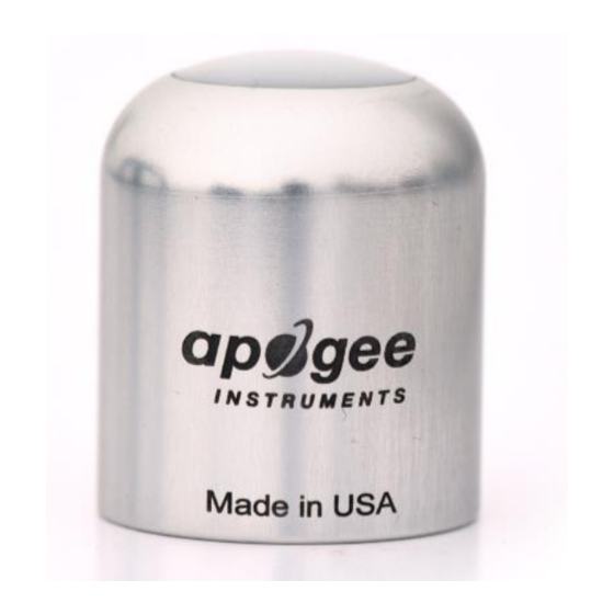
OWNER’S MANUAL ULTRAVIOLET-A SENSOR Models SU-200 (including SS models) APOGEE INSTRUMENTS, INC. | 721 WEST 1800 NORTH, LOGAN, UTAH 84321, USA TEL: (435) 792-4700 | FAX: (435) 787-8268 | WEB: APOGEEINSTRUMENTS.COM Copyright © 2020 Apogee Instruments, Inc. -
Page 2: Table Of Contents
TABLE OF CONTENTS Owner’s Manual ....................................1 Certificate of Compliance ................................. 3 Introduction ..................................... 4 Sensor Models ..................................5 Specifications ................................... 6 Deployment and Installation ..............................9 Cable Connectors ................................... 10 Operation and Measurement ..............................11 Maintenance and Recalibration ............................. 14 Troubleshooting and Customer Support .......................... -
Page 3: Certificate Of Compliance
RoHS 3 compliant using exemption 6c. Further note that Apogee Instruments does not specifically run any analysis on our raw materials or end products for the presence of these substances, but rely on the information provided to us by our material suppliers. -
Page 4: Introduction
Most UV sensors designed for sunlight measurements are sensitive to UV radiation in the UV-A or UV-B ranges. Apogee Instruments SU-200 series UV-A sensors detect UV radiation from 300 to 400 nm and are calibrated in energy flux density units of watts per square meter (W m , equal to Joules per second per square meter). -
Page 5: Sensor Models
SENSOR MODELS This manual covers the unamplified model SU-200 UV-A sensor (listed below in bold). Additional models are covered in their respective manuals. Model Signal SU-200 0-10 mV SU-202 0- 2.5 V SU-205 0- 5 V SU-220 Sensor model number and serial number are located on the bottom of the sensor. -
Page 6: Specifications
SPECIFICATIONS SU-200-SS Power Supply Self-Powered 0.1 mV per W m Output (sensitivity) 0.03 mV per µmol m⁻² s⁻¹ Calibration Factor (reciprocal of 10 W m per mV; sensitivity) 30 µmol m⁻² s⁻¹ per mV Calibration Uncertainty ± 10 % Output Range... - Page 7 Directional, or cosine, response is defined as the measurement error at a specific angle of radiation incidence. Directional error for Apogee SU-200 series UV-A sensors is approximately ± 2 % and ± 5 % at solar zenith angles of 45° and 75°, respectively.
- Page 8 Spectral Response Spectral response estimate of Apogee SU- 200 UV-A sensors. Spectral response was modeled from sensitivity of the photodetector and transmittance of the diffuser.
-
Page 9: Deployment And Installation
Mount the sensor to a solid surface with the nylon mounting screw provided. To accurately measure UV-A incident on a horizontal surface, the sensor must be level. An Apogee Instruments model AL-100 Leveling Plate is recommended to level the sensor when used on a flat surface or being mounted to surfaces such as wood. To facilitate mounting on a mast or pipe, the Apogee Instruments model AL-120 Solar Mounting Bracket with Leveling Plate is recommended. -
Page 10: Cable Connectors
CABLE CONNECTORS Apogee sensors offer cable connectors to simplify the process of removing sensors from weather stations for calibration (the entire cable does not have to be removed from the station and shipped with the sensor). The ruggedized M8 connectors are rated IP68, made of corrosion-resistant marine-grade stainless-steel, and designed for extended use in harsh Inline cable connectors are installed 30 cm from the... -
Page 11: Operation And Measurement
An input measurement range of approximately 0-10 mV is required to cover the entire range of the SU-200 UV-A sensor. In order to maximize measurement resolution and signal-to-noise ratio, the input range of the measurement device should closely match the output range of the UV sensor. DO NOT connect the sensor to a power source. - Page 12 Sensor Calibration The SU-200 has a standard UV calibration factor of exactly: 10.0 W m per mV Multiply this calibration factor by the measured mV signal to convert sensor output to UV-A in units of W m Calibration Factor (10 W m...
- Page 13 For most common lamps, the error is less than 10 %. The SU-200 is particularly useful for determining the UV-A filtering capacity of the transparent plastic and glass barriers that are commonly used below electric lamps.
-
Page 14: Maintenance And Recalibration
Blocking of the optical path between the target and detector can cause low readings. Occasionally, accumulated materials on the diffuser of the SU-200 UV-A sensor can block the optical path in three common ways: 1. Moisture or debris build-up on the diffuser. -
Page 15: Troubleshooting And Customer Support
TROUBLESHOOTING AND CUSTOMER SUPPORT Independent Verification of Functionality Apogee SU-200 sensors are self-powered devices and output a voltage signal proportional to incident UV-A radiation. A quick and easy check of sensor functionality can be determined using a voltmeter with millivolt resolution. - Page 16 Unit Conversion SU-200 series UV-A sensors are calibrated in energy flux units of W m . It is possible to convert the energy flux value to photon flux units of µmol m using a conversion factor. Below is an example of how to convert energy flux units to photon flux.
-
Page 17: Return And Warranty Policy
RETURN AND WARRANTY POLICY RETURN POLICY Apogee Instruments will accept returns within 30 days of purchase as long as the product is in new condition (to be determined by Apogee). Returns are subject to a 10 % restocking fee. WARRANTY POLICY... - Page 18 84321, USA 5. Upon receipt, Apogee Instruments will determine the cause of failure. If the product is found to be defective in terms of operation to the published specifications due to a failure of product materials or craftsmanship, Apogee Instruments will repair or replace the items free of charge.


Need help?
Do you have a question about the SU-200 and is the answer not in the manual?
Questions and answers