Table of Contents
Advertisement
Quick Links
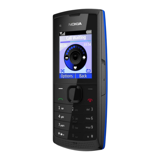
Nokia X1-00
RM-732 / RM-733
1
SERVICE MANUAL
Level 1&2
Transceiver characteristics
Band
RM-732:
EGSM 900/1800
RM-733:
EGSM 850/1900
RM-713:
EGSM 900/1800
Display
128x160 TFT display
Operating System
S30 system Base 9
Connections:
3.5 mm AV connector, Stereo FM radio, MicroSD card
support up to 16GB
Transceiver with BL-5J battery pack
Talk time (GSM-A)
BL-5J 1320 mAh:
7 h (RM-732/RM-733)
7 h (RM-713)
BL-5J 1430 mAh:
7.5 h (RM-732/RM-733)
7.5 h (RM-713)
Note:
Talk times are dependent on network parameters
and phone settings
Conf idential | Copyright © 2011 Nokia | A ll rights reserved
Nokia X1-00 (RM-732 / RM-733)
Nokia X1-01 (RM-713)
Service Manual Level 1&2
Nokia X1-01
RM-713
Standby (GSM-A)
BL-5J 1320 mAh:
1170 h (RM-732/RM-733)
785 h (RM-713)
BL-5J 1430 mAh:
1267 h (RM-732/RM-733)
850 h (RM-713)
Version 2.0
Advertisement
Table of Contents


Need help?
Do you have a question about the X1-00 RM-732 and is the answer not in the manual?
Questions and answers