Advertisement
ST - III Series POWER SUPPLIES
Introduction
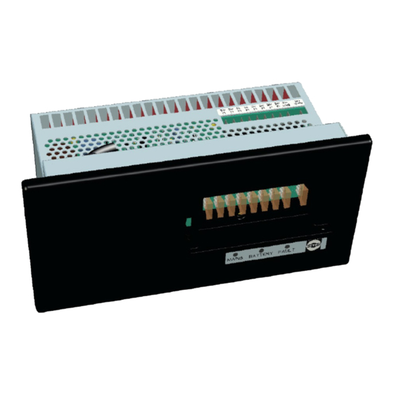
These instructions detail the installation and operation requirements for the ST20-III & ST35-III
power supplies. These have been designed for operation in RV's providing a DC power system,
with optional battery back up.
The units operate from 240Vac and provide an isolated 13.65Vdc output at 20A and 35A
respectively for powering the load and charging of batteries. All the necessary protection and
operating features for the load and batteries are provided. An optional DC input is also provided to
enable charging of batteries and powering of the load from an external +13.8V DC power source.
The units are fully enclosed ready for direct wall mounting. All connections are at the rear of unit
providing convenient wiring and installation. User access to all load and battery fusing has been
provided from the front of the unit.
Operation
Safety: Refer to the installation section before operating. Correct installation is the most critical
factor in ensuring the safe use of the power supply. If every consideration of these instructions has
been satisfied the power supply will be safe to operate.
If the AC supply cord is damaged it must be replaced by the manufacturer, its service agent or
similarly qualified persons in order to avoid hazard.
The unit is rated to charge a single 12V (up to 6 cells) lead acid battery at 100Ahr Capacity.
Functional Diagram:
DC External
Input
AC Input
USER MANUAL
AC / DC
Power Supply
Vadj
Battery Low Voltage
Disconnect circuit
Manual
Battery
Isolation
On / off
Input
Figure 1 Functional Block Diagram
Page 1 of 11
Fuse Panel
Isense
0.8A
Trickle
+ve
8 x Load
Outputs
-ve
+ve
Battery
Output
-ve
Doc 023942
Advertisement
Table of Contents


Need help?
Do you have a question about the ST - III Series and is the answer not in the manual?
Questions and answers