
Related Manuals for Sphere MPPT Series

Summary of Contents for Sphere MPPT Series
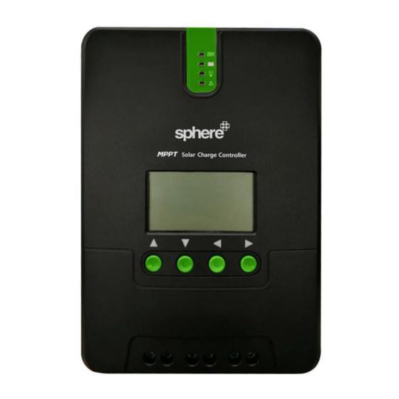
- Page 1 Maximum Power Point Tracking (MPPT) Series MPPT40 Solar Charge Controller User Manual More information https://www.caravansplus.com.au...
- Page 2 Model MPPT40 Battery voltage 12V/ 24V Max. solar panel voltage 100V (25°C), 90V (-25°C) Charging current Discharging current 20A* Dear users, Thank you for choosing our product! Safety Instructions 1. As this controller deals with voltages that exceed the top limit for human safety, do not operate it before reading this manual carefully and completing safety operation training.
-
Page 3: Table Of Contents
5. It's recommended that a fuse or breaker be installed outside the controller. 6. Before installing and wiring the controller, make sure to disconnect the photovoltaic array and the fuse or breaker close to the battery terminals. 7. After installation, check if all connections are solid and reliable so as to avoid loose connections that may give rise to dangers caused by heat accumulation. -
Page 4: Product Introduction
3.3 LCD Startup and Main Interface ................. 22 3.4 Load Mode Setting Interface ..................24 3.5 System Parameter Settings ..................25 4. Product Protection Function and System Maintenance ............26 4.1 Protection Functions ....................26 4.2 System Maintenance ....................28 4.3 Abnormality Display and Warnings ................ -
Page 5: Product Features
protection functions built inside the controller, component damage caused by installation errors or system failures can be avoided to the greatest extent possible. 1.2 Product Features With the advanced dual-peak or multi-peak tracking technology, when the solar panel ◆ is shadowed or part of the panel fails resulting in multiple peaks on the I-V curve, the controller is still able to accurately track the maximum power point. - Page 6 The controller is equipped with an LCD screen with which users can not only check ◆ device operating data and statuses, but also modify controller parameters. The controller supports standard Modbus protocol, fulfilling the communication needs ◆ of various occasions. The controller employs a built-in over-temperature protection mechanism.
- Page 7 Definition ○ Transmitting terminal TX ○ Receiving terminal RX ○ Power supply grounding /Signal grounding ○ Power supply grounding /Signal grounding ○ Power supply positive ○ Power supply positive Fig. 1-1 Product appearance and interfaces Item Item ○ ○ Charging indicator Battery "+"...
-
Page 8: Introduction To Maximum Power Point Tracking Technology
○ Solar panel "-" interface 1.4 Introduction to Maximum Power Point Tracking Technology Maximum Power Point Tracking (MPPT) is an advanced charging technology that enables the solar panel to output more power by adjusting the electric module's operating status. Due to the nonlinearity of solar arrays, there exists a maximum energy output point (maximum power point) on their curves. - Page 9 Fig. 1-2 Solar panel output characteristic curve Meanwhile, due to changing ambient temperature and illumination conditions, the max. power point varies frequently, and our MPPT controller can adjust parameter settings according to the environmental conditions in real time, so as to always keep the system close to the max.
-
Page 10: Charging Stages Introduction
I(A) 20℃ 30℃ 40℃ 太 阳 50℃ 温度降低,电流不变, With temperature dropping, current 板 功率增大 60℃ 温 stays stable and power increases 度 70℃ U(V) Open-circuit voltage decreases with rising temperature 温度升高,开路电压减小 Fig. 1-4 Relation between solar panel output characteristics and temperature 1.5 Charging Stages Introduction As one of the charging stages, MPPT cannot be used alone, but has to be used together with boost charging, floating charging, equalizing charging, etc. - Page 11 Time Fig. 1-5 Battery charging stages diagram a) Fast charging At the fast charging stage, as the battery voltage has not reached the set value of full voltage (i.e. equalizing/ boost voltage) When the battery yet, the controller will perform MPPT charging on the battery with the maximum solar power. voltage reaches the preset value, constant voltage charging will begin.
- Page 12 By default, boost charging generally lasts for 2h, but users can adjust preset values of duration and boost voltage point according to the actual needs. When the duration reaches the set value, the system will then switch to floating charging. Equalizing charging Warning: risk of explosion! In equalizing charging, an open lead-acid battery can produce explosive gas, therefore the...
-
Page 13: Product Installation
1) When due to the installation environment or working loads, the system can't continuously stabilize the battery voltage to a constant level, the controller will initiate a timing process, and 3 hours after the battery voltage reaches the set value, the system will automatically switch to equalizing charging. -
Page 14: Wiring Specifications
Keep the battery away from fire sparks, as the battery may produce flammable gas. ◆ When installing the battery outdoors, take sufficient measures to keep the battery ◆ from direct sunlight and rain water intrusion. Loose connections or corroded wire may cause excessive heat generation which may ◆... -
Page 15: Installation And Wiring
current current (mm2) (mm2) MPPT40 2.3 Installation and Wiring Warning: risk of explosion! Never install the controller and an open battery in the same enclosed space! Nor shall the controller be installed in an enclosed space where battery gas may accumulate. Warning: danger of high voltage! Photovoltaic arrays may produce a very high open-circuit voltage. - Page 16 Hot air Cold air Fig. 2.1 Installation and heat dissipation Step 1: choose the installation site Do not install the controller at a place that is subject to direct sunlight, high temperature or water intrusion, and make sure the ambient environment is well ventilated.
- Page 17 Step 4: wire First remove the two screws on the controller, and then begin wiring operation. In order to guarantee installation safety, we recommend the following wiring order; however, you can choose not to follow this order and no damage will be incurred to the controller. More information https://www.caravansplus.com.au...
- Page 18 ○ Connecting to external temperature sampling interface ○ Connecting communication cable ○ Connecting power cable Warning: risk of electric shock! We strongly recommend that fuses or breakers be connected at the photovoltaic array side, load side and battery side so as to avoid electric shock during wiring operation or faulty operations, and make sure the fuses and breakers are in open state before wiring.
-
Page 19: Product Operation And Display
Warning: when the controller is in normal charging state, disconnecting the battery will have some negative effect on the DC loads, and in extreme cases, the loads may get damaged. Warning: within 10 minutes after the controllers stops charging, if the battery's poles are reversely connected, internal components of the controller may get damaged. - Page 20 Steady on, charging in max. power 常亮,最大功率充电 慢闪,提升充电 Slow flashing, boost charging 单闪,浮充充电 Single flashing, floating charging 快闪,均衡充电 Quick flashing, equalizing charging 双闪,限流充电 Double flashing, current-limited charging Indicator state Charging state ○ Steady on MPPT charging ○ Slow flashing Boost (a cycle of 2s with on and off each charging lasting for 1s)
- Page 21 BAT indicator: Indicator state Battery state Normal battery voltage Steady on Slow flashing Battery over- (a cycle of 2s with on and off discharged each lasting for 1s) Quick flashing Battery over-voltage (a cycle of 0.2s with on and off each lasting for 0.1s) ...
-
Page 22: Key Operations
Steady on System malfunctioning 3.2 Key Operations Page up; increase the parameter value in ▲ setting Page down; decrease the parameter value in ▼ Down setting Return to previous menu (exit without ◄ Return saving) Enter into sub-menu; set/ save ►... - Page 23 3.3.1 Startup interface During startup, the 4 indicators will first flash successively, and after self- inspection, the LCD screen starts and displays the battery's voltage level which will be either a fixed voltage selected by the user or a voltage automatically recognized.
-
Page 24: Load Mode Setting Interface
Main monitoring page Charging current Component voltage Battery voltage Battery capacity Abnormality code Charging capacity Load current Device temperature Load mode Discharging capacity 3.4 Load Mode Setting Interface 3.4.1 Load modes introduction This controller has 5 load operating modes which will be described below: Mode Descriptions When no sunlight is present, the solar panel voltage is lower than the light control on... -
Page 25: System Parameter Settings
signals, the load is switched on. This mode enables fast check of the correctness of system installation during installation debugging. The energized load keeps outputting, and this mode is suitable for loads which need 24- Normal on mode hour power supply. 3.4.2 Load mode adjustment Users can adjust the load mode as needed on their own, and the default mode is Manual mode (see "load modes introduction"). -
Page 26: Product Protection Function And System Maintenance
Note: after system voltage setting, power supply has to be switch off and then on again, otherwise the system may work under an abnormal system voltage. The controller enables users to customize the parameters according to the actual conditions, but parameter setting must be done under the guidance of a professional person, or else faulty parameter settings may render the system not able to function normally. - Page 27 Battery reverse connection protection If the battery is reversely connected, the system will simply not operate so as to protect the controller from being burned. Photovoltaic input side too high voltage protection If the voltage on the photovoltaic array input side is too high, the controller will automatically cut off photovoltaic input.
-
Page 28: System Maintenance
Chg-P :/% 100% 67 68 69 70 71 72 73 74 75 76 77 78 79 Tem-MOS :/℃ Fig. 4-1 4.2 System Maintenance In order to always keep the controller's performance at its optimum level, we ◆ recommend that the following items be checked twice a year. Make sure the airflow around the controller is not blocked and clear away any dirt ◆... -
Page 29: Abnormality Display And Warnings
4.3 Abnormality Display and Warnings Error display Description LED indication ERROR indicator No abnormality BAT indicator Battery over- flashing slowly discharge ERROR indicator steady on BAT indicator System over- flashing quickly voltage ERROR indicator steady on Battery under- ERROR indicator voltage warning steady on LOAD indicator... -
Page 30: Electric Parameters
5.1 Electric Parameters Parameter Value Model MPPT40 System voltage 12V/24V Auto No-load loss 0.7 W to 1.2W Battery voltage 9 to 35 Max. solar input voltage 100V (25°C), 90V (-25°C) Max. power point voltage Battery voltage +2V to 75V range Rated charging current Rated load current Max. -
Page 31: Battery Type Default Parameters (Parameters Set In Monitor Software)
5.2 Battery Type Default Parameters (parameters set in monitor software) Parameters cross-reference table for different types of batteries Sealed lead- Gel lead-acid Open lead-acid User (self- Voltage to set Li battery acid battery battery battery customized) Battery type Over-voltage cut-off ——... -
Page 32: Conversion Efficiency Curve
voltage; Under-voltage warning return voltage > Under-voltage warning voltage ≥ Discharging limit voltage; Boost return voltage > Low-voltage cut-off return voltage 6. Conversion Efficiency Curve 6.1 12V System Conversion Efficiency MPPT 12V conversion efficiency (12V battery) Output power(W) More information https://www.caravansplus.com.au... -
Page 33: System Conversion Efficiency
6.1 24V System Conversion Efficiency MPPT 24V conversion efficiency (24V battery) Output power(W) 7. Product Dimensions MPPT40 Product dimensions Hole positions Hole diameter Applicable wire: max. 8 AWG More information https://www.caravansplus.com.au... - Page 34 Coast RV Pty Ltd trading as Coast to Coast RV Services ABN 49 097 104 492 - ACN 101 461 330 PO Box 415, Regents Park NSW 2143 Ph (02) 9645 7600 - Fax (02) 9645 7699 Email: warranty@coastrv.com.au Web: www.coastrv.com.au Warranty Against Defects WHAT THIS WARRANTY RELATES TO This warranty covers goods supplied by Coast RV Pty Ltd T/A Coast to Coast RV Services ("Supplier") to the...
- Page 35 WARRANTY LIMITATIONS The Supplier makes no warranties or representations other than those set out in this warranty document except as is required by law. The Supplier will not be liable under this warranty:- to the Client or any other person for any consequential, direct or indirect loss, damage or costs incurred or suffered by the Client or any other person, including but not limited to damage to persons, other property, loss of turnover, loss of profits, loss of business or goodwill;...
- Page 36 WARRANTY CLAIM FORM Warranty Providers Name: Coast RV Pty Ltd trading as Coast to Coast RV Services ABN 49 097 104 492 - ACN 101 461 330 Warranty Providers Address: PO Box 415 Regents Park NSW 2143 Client: Contact No. Description of Goods provided: ...
Need help?
Do you have a question about the MPPT Series and is the answer not in the manual?
Questions and answers