
Related Manuals for AUDAC DW5065


Summary of Contents for AUDAC DW5065
- Page 1 DW5065 User Manual & Installation Guide Digital All-In-One Wall Panel www.audac.eu...
- Page 3 Index Introduction Chapter 1: Overview of DW5065 Overview front panel Front panel description Overview rear panel Rear panel description Chapter 2: Quick start guide Chapter 3: Installing, Connecting & Configuring Installing Connecting Configuring Chapter 4: Using the DW5065 Chapter 5: Technical Specifications...
- Page 5 Introduction Digital All-In-One Wall Panel The DW5065 is an All-in-one wall panel designed to work in combination with AUDAC digital matrix systems. This wall panel has a graphic display and can control the routing, volume, bass, treble and mute for multiple zones (up to 8) on one R2. Besides those control functions, it also provides the possibility to connect a microphone and a stereo line input source.
-
Page 6: Overview Front Panel
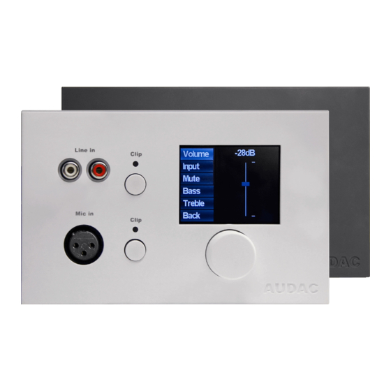
Chapter 1 Overview front panel The front panel of the DW5065 wall panel contains a 2.5” Graphic color LCD display with an unbalanced line input connected by RCA connectors and a balanced microphone input connected by an XLR connector. Each input is accomodated with a push-lock gain control potentiometer and a Clip indicator LED. -
Page 7: Front Panel Description
Front panel description Unbalanced line input An unbalanced stereo audio source can be connected to these RCA connectors, creating an additional local input. Push-Lock gain control potentiometer with clipping LED The sensitivity for the line and microphone inputs can be adjusted with these potentiometers. Through the push-lock mechanism, they can be opened and hidden again by pressing them. - Page 8 2.5” Graphic color LCD display This graphical color LCD displays gives a clear overview of all the functions and settings of the wall panel. Rotatable function selection dial The big rotatable dial enables you to control all functions and settings of the wall panel by just three simple actions: Rotate left, Rotate right and Push.
-
Page 9: Overview Rear Panel
Overview rear panel The rear panel of the DW5065 contains an 8 pin connector for connecting the wall panel to the matrix system and a jumper which is meant for terminating the RS485 databus. A detailed description of how the DW5065 should be connected, can be found in the chapter “Connecting the DW5065”. The jumper for terminating the databus should always be placed when only one wall panel is connected to the databus, and is always provided and placed by delivery. - Page 10 Connect the DW5065 wall panel to the Matrix system with a twisted pair CAT6 cabling with a maximum cable length of 300 meters. Make sure the DW5065 is connected to one of the PI ports on the rear side of the digital audio matrix (Only PI 1-8 can handle audio inputs).
- Page 11 After the desired address is selected, click the “Set Address” button. A message will start blinking on all the DW5065 wall panels connected in your system. When the function selection dial on the wall panel is pressed, the selected address will be assigned to the corresponding wall panel.
- Page 12 Installing, Connecting & Configuring Installing For installing the DW5065, two different kinds of flush mount installation boxes are available. The plastic installation box (WB5065/FG) is meant to be used for installation into gypsum, wooden or other kinds of plate walls with a thickness between 7 mm and 25 mm. An installation hole with dimensions 135 x 75 mm should be cut wherein the installation box should be placed.
- Page 13 Connecting The DW5065 wall panels should be connected to the PI (Peripheral Interface) ports on the rear side of the matrix system with an UTP CAT6 twisted pair cable. 10 PI ports are available (PI1 to PI10) where 8 of them support addidional digital audio inputs (PI1 to PI8). So make sure the DW5065 wall panels are connected to PI ports ranging from 1 to 8.
- Page 14 ATTENTION The twisted pair cabling must always be ‘straight’. In case of self made cabling, it must be wired as described in this chapter to make the system work properly. The twisted pair cable should be connected to the 8-pin Euro-Terminal block connector on the rear side of the wall panel.
-
Page 15: Connection Possibilities
LINE IN Prog. Prog. LINE IN LINE IN MIC IN MIC IN AUDAC MIC IN AUDAC AUDAC Multiple wall panels (only one with audio input) on one PI port Multiple wall panels with audio input on one PI port LINE IN... - Page 16 After the desired address is selected, click the “Set address” button. After this button is pressed, the DW5065 will start blinking. To confirm the selected address with the wall panel, click the big rotary button on the front of the wall panel. When this button is pressed, the address will...
- Page 17 “Remove Input” button. A maximum of 24 signal inputs can be selected. The inputs which are selected in this listbox, are available for all zones which can be controlled by this DW5065 wall panel. Those inputs are not linked with the quick menu like the inputs on the DW3018/4018 are.
- Page 18 6) The Backlight level, screensaver and screensaver delay can be set by means of three dropdown boxes.This setting can also be changed in the DW5065 settings menu. (If “Block settings menu” is not checked) 7) When the settings are made, press the “Save to Wallpanel” button and the settings will be send to the selected DW5065 wall panel.
- Page 19 When the DW5065 is correctly installed, connected and configured, the wall panel is ready for opera- tion. The standard screen of the DW5065 will give an overview of all zones which are configured to be controlled by means of the DW5065 wall panel. The zone names displayed on this screen correspond with the zone settings which are set in the user interface of the matrix.
- Page 20 When the desired zone is selected, you will proceed to the settings menu for the corresponding zone. Settings such as Volume control, Input signal selection, Mute and Tone control can be made for the corresponding zone. On the left side of the display are all the possible settings displayed, and scrolling between the settings can be done by rotating the selection dial.
- Page 21 When “Input” is lit, you can push this button and you will be redirected to the input selection window. This window shows all (configured) input channels which can be selected. The displayed input names correspond with the input names which are configured in the matrix settings.
- Page 22 The latest settings which can be changed to the zones are the two band tone control. The tone control can be activated by selecting the “Bass” and “Treble” buttons, and the adjustment of the tone control works with a fader just as the volume control.
- Page 23 When returning back to the main menu, the latest selectable option is “Settings”. By selecting this option, changes to the settings of the wall panel can be made. After clicking this button, you will be redirected to the settings menu. The settings menu shows different options like: “Mic Phantom”, “Backlight”, “Screensaver”...
-
Page 25: Technical Specifications
Chapter 5 Technical Specifications Line input Stereo, RCA input Sensitivity: +8dB / -6dB Signal / Noise: > 95 dB THD+N: < 0.02 Microphone input Balanced, XLR input Sensitivity: -14dB / -50dB Signal / Noise: > 75 dB THD+N: < 0.05 Phantom power 15V DC Display... - Page 26 Chapter 6 Notes...
Need help?
Do you have a question about the DW5065 and is the answer not in the manual?
Questions and answers