Table of Contents
Advertisement
Quick Links
Cedar Ridge
h e a r t h
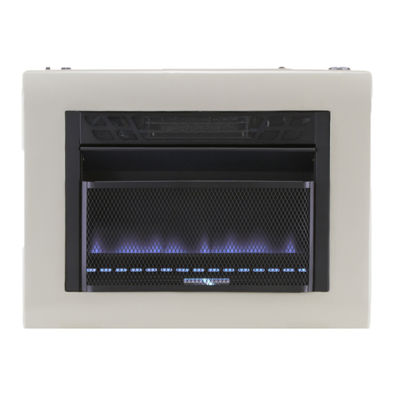
VENT-FREE GAS WALL HEATER
OWNER'S OPERATION AND
INSTALLATION MANUAL
BLUE FLAME MODELS
CH10TBU, CH20TBU & CH30TBU
PFS
WARNING: If the information in this manual is not
followed exactly, a fire or explosion may result causing
property damage, personal injury or loss of life.
— Do not store or use gasoline or other flammable va-
pors and liquids in the vicinity of this or any other
appliance.
— WHAT TO DO IF YOU SMELL GAS
• Do not try to light any appliance.
• Do not touch any electrical switch; do not use any
phone in your building.
• Immediately call your gas supplier from a neighbor's
phone. Follow the gas supplier's instructions.
• If you cannot reach your gas supplier, call the fire
department.
— Installation and service must be performed by a quali-
fied installer, service agency or the gas supplier.
WARNING: This appliance is equipped for Natural and
Propane gas. Field conversion is not permitted other than
between natural or propane gases.
Questions, problems, missing parts? Before returning to your retailer, call
our customer service department at 1-855-607-6557, 8:00 am - 4:30 pm EST,
®
®
US
Monday through Friday or email info@factorybuysdirect.com
For Patent Information
See Page 4.
30,000 BTU/hr
Shown
Advertisement
Table of Contents

Related Manuals for Cedar Ridge CH10TBU


Summary of Contents for Cedar Ridge CH10TBU
- Page 1 VENT-FREE GAS WALL HEATER OWNER’S OPERATION AND INSTALLATION MANUAL BLUE FLAME MODELS CH10TBU, CH20TBU & CH30TBU ® 30,000 BTU/hr Shown WARNING: If the information in this manual is not followed exactly, a fire or explosion may result causing property damage, personal injury or loss of life.
-
Page 2: Table Of Contents
TABLE OF CONTENTS Safety ............3 Electrical Connection ....... 20 Qualified Installing Agency ......4 Electrical Wiring ........20 Specifications ..........5 Inspecting Burners........21 Product Features ........6 Care And Maintenance ......22 Local Codes..........6 Troubleshooting ........23 Preparing For Installation ...... -
Page 3: Safety
SAFETY NATURAL AND PROPANE/LP GAS: Natural IMPORTANT: Read this owner’s and Propane/LP gas are odorless. An odor- manual carefully and completely making agent is added to the gas. The odor before trying to assemble, op- helps you detect a gas leak. However, the erate, or service this heater. -
Page 4: Qualified Installing Agency
SAFETY 1. Do not place Propane/LP supply tank(s) 7. Before using furniture polish, wax, carpet inside any structure. Propane/LP supply cleaner, or similar products, turn heater tank(s) must be placed outdoors. off. If heated, the vapors from these prod- ucts may create a white powder residue 2. -
Page 5: Specifications
SPECIFICATIONS Model CH10TBU Model CH20TBU Ignition Electric Piezo Ignitor Gas Type Natural Gas Propane Gas Natural Gas Propane Gas BTU/Hr Input Max. (available) 10,000 10,000 20,000 20,000 BTU/Hr Input Min. (available) 5,000 8,000 10,000 16,000 Pressure Regulator Setting 4" W.C. -
Page 6: Product Features
PRODUCT FEATURES SAFETY PILOT 2 GAS OPTIONS AVAILABLE This heater has a pilot with an Oxygen Deple- Your heater is equipped to operate on either tion Sensing (ODS) safety shutoff system. The Propane/LP or Natural gas. The heater is ODS/pilot shuts off the heater if there is not shipped from the factory ready for connect- enough fresh air. -
Page 7: Unpacking
UNPACKING 1. Remove heater from carton. 3. Check heater for any shipping damage. If heater is damaged, promptly inform dealer 2. Remove all protective packaging applied where you bought heater. to heater for shipping WATER VAPOR: A BY-PRODUCT OF UNVENTED ROOM HEATERS Water vapor is a by-product of gas combus- The following steps will help ensure that water tion. - Page 8 AIR FOR COMBUSTION AND VENTILATION VENTILATION AIR Ventilation Air From Inside Building Ventilation Air From Outdoors Provide extra fresh air by using ventilation This fresh air would come from an adjoining grills or ducts. You must provide two perma- unconfined space. When ventilating to an nent openings: one within 12"...
-
Page 9: Installation
INSTALLATION IMPORTANT: Vent-free heaters add moisture NOTICE: This heater is intended to the air. Although this is beneficial, installing for use as supplemental heat. heater in rooms without enough ventilation air Use this heater along with your may cause mildew to form too much moisture. primary heating system. - Page 10 INSTALLATION INSTALLING THERMOSTAT SENSING BULB (OPTIONAL) 1. Pull out the sensing bulb from the two clips located in the shipping position. There is no need to take out the two bulb clips. 2. Take out the bulb clip from the hardware package and insert it into the square hole.
- Page 11 INSTALLATION Attaching Mounting Bracket To Wall IMPORTANT: Do not hammer anchor key! For Note: Wall anchors, mounting screws, and thick walls (over 1/2" thick) or solid walls, do spacers are in hardware package. The hard- not pop open wings. ware package is provided with heater. 5.
- Page 12 INSTALLATION INSTALLING OPTIONAL BASE FEET (See Accessories, page 27) 1. Snap the left and right foot columns to- 5. Position the heater to the desired location. gether (see Figure 11). Secure the base feet to the floor by us- ing two Phillips head self tapping screws 2.
- Page 13 INSTALLATION GAS SELECTION This appliance is factory INLET GAS PRESSURE preset for propane/LP gas. MAX 1/2 PSIG (3.5 KPA) No changes are required for connecting to propane/LP. Only a qualified installer or service technician can perform gas selec- tion and connecting to gas supply. Gas Connection CAUTION: Two gas line in- Figure 14 - Bottom of Heater...
- Page 14 INSTALLATION 2. Apply thread sealant to the threads on Use only the cap supplied on the the connection fitting. While pushing in, regulator. Do not use an off the rotate the fitting clockwise until the threads shelf pipe plug. This can damage engage the regulator.
- Page 15 INSTALLATION CONNECTING TO GAS SUPPLY WARNING: A qualified ser- CAUTION: For propane/LP vice technician must connect gas, Never connect heater directly to the gas supply. This heater heater to gas supply. Follow all requires an external regulator local codes. (not supplied). Install the external WARNING: This appliance regulator between the heater and requires a 3/8"...
- Page 16 INSTALLATION Typical Inlet Pipe Diameters ing gas pressure. You must reduce incoming Use 3/8" black iron pipe or greater. Installa- gas pressure to between 11" and 14" of water. tion must include an equipment shutoff valve, If you do not reduce incoming gas pressure, union, and plugged 1/8"...
- Page 17 INSTALLATION CHECKING GAS CONNECTIONS WARNING: Test all gas piping WARNING: Never use an open and connections for leaks after flame to check for a leak. Apply a installing or servicing. Correct mixture of liquid soap and water all leaks at once. to all joints.
-
Page 18: Operation
OPERATION FOR YOUR SAFETY READ BEFORE LIGHTING • Immediately call your gas supplier WARNING: If you do not fol- from a neighbor’s phone. Follow the low these instructions exactly, a gas supplier’s instructions. fire or explosion may result caus- • If you cannot reach your gas supplier, call the fire department. - Page 19 OPERATION 7. Keep control knob pressed in for 30 sec- WARNING: If input gas onds after lighting pilot. After 30 seconds, type is NG, make sure NG pilot release control knob. If control knob does not pop up when released, contact a quali- burner ignites.
-
Page 20: Electrical Connection
ELECTRICAL CONNECTION FOR OPTIONAL BLOWER KIT Do not use this heater if any part of it has been under water. Immediately call a qualified ser- vice technician to inspect the Cover of heater and replace any part of Grounded Grounding Pin Outlet Box the electrical system which has been under water. -
Page 21: Inspecting Burners
INSPECTING BURNERS IMPORTANT: Owner’s should check pilot flame pattern and burner flame pattern often. Incorrect flame patterns indicate the need for cleaning (see Care and Maintenance, page 22) or service. WARNING: Only a qualified service person should service and repair heater. This includes maintenance requiring replacement or alteration of components. -
Page 22: Care And Maintenance
CARE AND MAINTENANCE WARNING: Turn off heater and let cool before servicing. CAUTION: You must keep control areas, burner, and circulating air passageways of heater clean. Inspect these areas of heater before each use. Have heater inspected yearly by a qualified service techni- cian. -
Page 23: Troubleshooting
CARE AND MAINTENANCE MAINTENANCE OF BLOWER MOTOR Always disconnect the appliance from the heavy or continuous use, periodic cleaning main power supply and allow it to cool must be done more frequently. If the heater before any servicing operation. blows alternating cold and warm air, check the fan for free movement and for debris restrict- The motors used on the fan heater and flame ing air flow. - Page 24 TROUBLESHOOTING The entire gas delivery piping including con- nections inside the heater should be leak tested by the qualified installer. After leak testing the qualified installer should light the appliance. Refer to the correct flame pattern as illustrated on page 21. All flame patterns should be safely inside the product.
- Page 25 TROUBLESHOOTING Problem Possible Cause Corrective Action ODS/pilot lights but flame 1. Control knob is not fully 1. Press in control knob fully. goes out when control pressed in. knob is released. 2. Control knob is not pressed 2. After ODS/pilot lights, keep in long enough.
- Page 26 TROUBLESHOOTING Problem Possible Cause Corrective Action Heater produces a whis- 1. Turning control knob to high 1. Turn control knob to low (1) tling noise when burner (5) position when burner is position and let warm up for is lit. cold.
-
Page 27: Replacement Parts
REPLACEMENT PARTS Note: Use only original replacement parts. This will protect your warranty coverage for parts replaced under warranty. PARTS UNDER WARRANTY Contact authorized dealers of this product. • Model and serial number of your heater If they can’t supply original replacement •... -
Page 28: Parts
PARTS MODEL CH10TBU www.factorybuysdirect.com 200308-01A... - Page 29 PARTS MODEL CH10TBU This list contains replaceable parts for your heater. When ordering replacement parts, follow the instructions listed under Replacement Parts on page 27 of this manual. ITEM PART # DESCRIPTION Back Body Panel Front Panel Assembly ML083-04 Piezo Ignitor...
- Page 30 PARTS MODELS CH20TBU AND CH30TBU www.factorybuysdirect.com 200308-01A...
- Page 31 PARTS MODELS CH20TBU AND CH30TBU This list contains replaceable parts for your heater. When ordering replacement parts, follow the instructions listed under Replacement Parts on page 27 of this manual. ITEM CH20TBU CH30TBU DESCRIPTION Front Panel Assembly UBD20T-140B UBD30T-140B Back Body Panel MB060-02 MB060-01 Mounting Bracket...
-
Page 32: Warranty
WARRANTY KEEP THIS WARRANTY Model _______________________________ Serial No. ____________________________ Date Purchased _______________________ Keep receipt for warranty verification. REGISTER YOUR PRODUCT AT WWW.FACTORYBUYSDIRECT.COM FACTORY BUYS DIRECT LIMITED WARRANTIES New Products Standard Warranty: Factory Buys Direct warrants this new product and any parts thereof to be free from defects in material and workmanship for a period of one (1) year from the date of first purchase from an authorized dealer provided the product has been installed, maintained and operated in accordance with Factory Buys Direct’s warnings and instructions.
Need help?
Do you have a question about the CH10TBU and is the answer not in the manual?
Questions and answers