Table of Contents
Advertisement
Available languages
Available languages
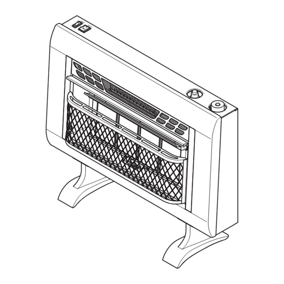
Cedar Ridge
h e a r t h
VENT-FREE GAS WALL
HEATER
OWNER'S OPERATION AND
INSTALLATION MANUAL
INFRARED MODEL
MTF4TPU
PFS
WARNING: If the information in this manual is not
followed exactly, a fire or explosion may result causing
property damage, personal injury or loss of life.
— Do not store or use gasoline or other flammable va-
pors and liquids in the vicinity of this or any other
appliance.
— WHAT TO DO IF YOU SMELL GAS
• Do not try to light any appliance.
• Do not touch any electrical switch; do not use any
phone in your building.
• Immediately call your gas supplier from a neighbor's
phone. Follow the gas supplier's instructions.
• If you cannot reach your gas supplier, call the fire
department.
— Installation and service must be performed by a quali-
fied installer, service agency or the gas supplier.
WARNING: This appliance is equipped for Natural and
Propane gas. Field conversion is not permitted other than
between natural or propane gases.
Questions, problems, missing parts? Before returning to your retailer, call
our customer service department at 1-866-573-0674, 8:00 am - 4:30 pm CST,
Monday through Friday or email customerservice@usaprocom.com
®
®
US
Advertisement
Chapters
Table of Contents

Subscribe to Our Youtube Channel
Related Manuals for Cedar Ridge MTF4TPU


Summary of Contents for Cedar Ridge MTF4TPU
- Page 1 Cedar Ridge ® h e a r t h VENT-FREE GAS WALL HEATER OWNER’S OPERATION AND INSTALLATION MANUAL INFRARED MODEL MTF4TPU ® WARNING: If the information in this manual is not followed exactly, a fire or explosion may result causing property damage, personal injury or loss of life.
-
Page 2: Table Of Contents
TABLE OF CONTENTS Safety ............3 Operation ..........19 Specifications ..........4 Electrical Connection ....... 21 Important Electrical Safety Information..5 Electrical Wiring Diagram ......22 Qualified Installing Agency ......6 Inspecting Burners........23 Product Features ........6 Care And Maintenance ......24 Local Codes.......... -
Page 3: Safety
SAFETY NATURAL AND PROPANE/LP GAS: Natural IMPORTANT: Read this owner’s and Propane/LP gas are odorless. An odor- manual carefully and completely making agent is added to the gas. The odor before trying to assemble, op- helps you detect a gas leak. However, the erate, or service this heater. -
Page 4: Specifications
100 lbs. capacity. 6. Do not run heater: • Where flammable liquids or vapors are used or stored. • Under dusty conditions. SPECIFICATIONS Model MTF4TPU Gas Type Natural Gas Propane Gas Ignition Electric Piezo Ignitor Electric Piezo Ignitor BTU/Hr (available) -
Page 5: Important Electrical Safety Information
IMPORTANT ELECTRICAL SAFETY INFORMATION When using electrical appliances, basic pre- 9. To disconnect heater, turn controls to OFF, cautions should always be followed to reduce then remove plug from outlet. the risk of fire, electric shock, and injury to 10. Connect to properly grounded outlets only. persons, including the following: 11. -
Page 6: Qualified Installing Agency
QUALIFIED INSTALLING AGENCY Only a qualified agency should install and a) Installing, testing, or replacing gas piping replace gas piping, gas utilization equipment or accessories, and repair and equipment ser- b) Connecting, installing, testing, repairing, vicing. The term “qualified agency” means any or servicing equipment;... -
Page 7: Preparing For Installation
PREPARING FOR INSTALLATION Blower Switch Before beginning assembly or operation of the product, make sure all parts are present. Heater Switch Compare parts with package contents list and Figure 1. If any part is missing or damaged, Ignitor do not attempt to assemble, install or operate Button Control the product. -
Page 8: Air For Combustion And Ventilation
AIR FOR COMBUSTION AND VENTILATION heat loss in homes. Home owners weather WARNING: This heater shall strip and caulk around windows and doors not be installed in a confined space to keep the cold air out and the warm air in. During heating months, home owners want or unusually tight construction their homes as airtight as possible. - Page 9 AIR FOR COMBUSTION AND VENTILATION DETERMINING FRESH-AIR FLOW FOR HEATER LOCATION Determining if You Have a Confined 4. Compare the maximum Btu/Hr the space or Unconfined Space can support with the actual amount of Btu/ Use this work sheet to determine if you have Hr used.
- Page 10 AIR FOR COMBUSTION AND VENTILATION VENTILATION AIR Ventilation Air From Inside Building This fresh air would come from an adjoining 1 and 2, Figure 2). You can also remove door unconfined space. When ventilating to an into adjoining room (see option 3, Figure 2). adjoining unconfined space, you must provide Follow the National Fuel Gas Code, ANSI two permanent openings: one within 12"...
-
Page 11: Installation
INSTALLATION IMPORTANT: Vent-free heaters add moisture NOTICE: This heater is intended to the air. Although this is beneficial, installing for use as supplemental heat. heater in rooms without enough ventilation air Use this heater along with your may cause mildew to form too much moisture. primary heating system. - Page 12 INSTALLATION INSTALLING THERMOSTAT SENSING BULB (OPTIONAL) 1. Pull out the sensing bulb from the two clips located in the shipping position. There is no need to take out the two bulb clips. 2. Take out the bulb clip from the hardware package and insert it into the square hole.
- Page 13 INSTALLATION Marking Screw Locations 3. Insert mounting screws through bracket 1. Tape mounting bracket to wall where and into wall studs. heater will be located. Make sure mount- 4. Tighten screws until mounting bracket is ing bracket is level. firmly fastened to wall studs. Attaching to Wall Anchor Method WARNING: Maintain mini- For attaching mounting bracket to hollow...
- Page 14 INSTALLATION Placing Heater On Mounting Horizontal Bracket Slots 1. Locate two horizontal slots on back panel Stand-Out of heater (see Figure 11). 2. Place heater onto mounting bracket. Slide horizontal slots onto stand-out tabs on mounting bracket. Mounting Bracket (attached to wall) Figure 11 - Mounting Heater Onto Mounting Bracket INSTALLING BASE FEET...
-
Page 15: Natural Gas Supply
INSTALLATION GAS SELECTION 3. Rotate and close cover over fuel selection This appliance is factory device and reinstall screw. preset for propane/LP gas. 4. Remove hex plug (with wrench provided) No changes are required for from natural gas inlet of regulator (see connecting to propane/LP. - Page 16 INSTALLATION CONNECTING TO GAS SUPPLY WARNING: A qualified ser- CAUTION: For propane/ vice technician must connect LP gas, Never connect heater heater to gas supply. Follow all directly to the gas supply. This local codes. heater requires an external regulator (not supplied). Install WARNING: This appliance the external regulator between requires a 3/8"...
-
Page 17: Checking Gas Connections
INSTALLATION Apply pipe joint sealant lightly to male threads. external regulator with the vent pointing down This will prevent excess sealant from going as shown in Figure 18. Pointing the vent down into pipe. Excess sealant in pipe could result protects it from freezing rain or sleet. - Page 18 INSTALLATION Test Pressures Equal To or Less Than 1/2 PSIG (3.5 kPa) 1. Close equipment shutoff valve (see Fig- Propane/LP Gas Valve Supply Tank ure 19). 2. Pressurize supply piping system by either using compressed air or opening gas sup- ply valve.
-
Page 19: Operation
OPERATION FOR YOUR SAFETY READ BEFORE LIGHTING • Immediately call your gas supplier WARNING: If you do not fol- from a neighbor’s phone. Follow the low these instructions exactly, a gas supplier’s instructions. fire or explosion may result caus- • If you cannot reach your gas supplier, call the fire department. -
Page 20: To Turn Off Gas To Appliance
OPERATION 6. With control knob pressed in, push Note: If pilot goes out, repeat steps 2 down and release ignitor button. This through 6. This heater has a safety inter- will light pilot. The pilot is attached to lock system. Wait one (1) minute before the front of burner. -
Page 21: Electrical Connection
OPERATION SWITCHES OPERATION Heating Heating Coil Switch Working When the switch is on I, the blower and heat- Heating Light ing coil turn on at the same time. It makes the Coil Switch room temperature rises rapidly. Blower Switch When the blower and heating coil switch is on O, turn the blower switch to I then the Blower blower turns on. -
Page 22: Electrical Wiring Diagram
ELECTRICAL WIRING DIAGRAM Any electrical re-wiring of this appliance must CAUTION: Label all wires be done by a qualified electrician. This wiring prior to disconnection when must be done in accordance with local codes servicing controls. Wiring errors and/or in Canada with the current CSA C22.1 Canadian Electrical Code, and for US instal- can cause improper and danger- lations, the National Electrical Code ANSI/... -
Page 23: Inspecting Burners
INSPECTING BURNERS IMPORTANT: Owner’s should check pilot flame pattern and burner flame pattern often. Incorrect flame patterns indicate the need for cleaning (see Care and Maintenance, page 24) or service. WARNING: Only a qualified service person should service and repair heater. This includes maintenance requiring replacement or alteration of components. -
Page 24: Care And Maintenance
CARE AND MAINTENANCE WARNING: Turn off heater and let cool before servicing. CAUTION: You must keep control areas, burner, and circulating air passageways of heater clean. Inspect these areas of heater before each use. Have heater inspected yearly by a qualified service techni- cian. -
Page 25: Troubleshooting
CARE AND MAINTENANCE MAINTENANCE OF BLOWER MOTOR Always disconnect the appliance from the heavy or continuous use, periodic cleaning main power supply and allow it to cool must be done more frequently. If the heater before any servicing operation. blows alternating cold and warm air, check the fan for free movement and for debris restrict- The motors used on the fan heater and flame ing air flow. - Page 26 TROUBLESHOOTING Problem Possible Cause Corrective Action When ignitor button is 1. Gas supply is turned off or 1. Turn on gas supply or open pressed in there is a equipment shutoff valve is equipment shutoff valve. spark at ODS/pilot but closed.
- Page 27 TROUBLESHOOTING Problem Possible Cause Corrective Action High yellow flame during 1. Not enough air. 1. Check burner for dirt and debris. burner combustion If found, clean burner (see Care and Maintenance, page 24). 2. Gas regulator is defective. 2. Replace gas regulator. 3.
-
Page 28: Parts
PARTS MODEL MTF4TPU www.usaprocom.com 200032-01A... - Page 29 PARTS MODEL MTF4TPU This list contains replaceable parts for your heater. When ordering replacement parts, follow the instructions listed under Replacement Parts on page 30 of this manual. ITEM PART # DESCRIPTION UBD4T-101 Body Panel UBD4T-102 Front Panel UBD4T-130B Screen Assembly...
-
Page 30: Replacement Parts
REPLACEMENT PARTS Note: Use only original replacement parts. This will protect your warranty coverage for parts replaced under warranty. PARTS UNDER WARRANTY Contact authorized dealers of this product. • Model and serial number of your heater If they can’t supply original replacement •... -
Page 31: Service Hints
SERVICE HINTS When Gas Pressure Is Too Low • pilot will not stay lit • burners will have delayed ignition • fireplace will not produce specified heat • propane/LP gas supply might be low (propane/LP units only) You may feel your gas pressure is too low. If so, contact your local gas supplier. TECHNICAL SERVICE You may have further questions about installation, operation, or troubleshooting. -
Page 32: Warranty
WARRANTY KEEP THIS WARRANTY Model _______________________________ Serial No. ____________________________ Date Purchased _______________________ Keep receipt for warranty verification. REGISTER YOUR PRODUCT AT WWW.USAPROCOM.COM IMPORTANT: We urge you to register your product within 10 days of date of installation, complete with entire serial number which can be found on the rating plate. Please fill out the warranty infor- mation above for your personal records. - Page 33 Cedar Ridge ® h e a r t h CALENTADOR DE GAS DE PARED SIN VENTILAS MANUAL DE FUNCIONAMIENTO E INSTALACIÓN DEL PROPIETARIO INFRARROJO MODELO MTF4TPU ® ADVERTENCIA: Si la información contenida en este manual no se sigue al pie de la letra, se pueden producir un incendio o una explosión que podrían ocasionar daños...
- Page 34 TABLA DE CONTENIDOS Seguridad ..........35 Funcionamiento ........53 Especificaciones ........38 Conexión Eléctrica........56 Agencia De Instalación Calificada ... 38 Diagrama Del Cableado Eléctrico ... 57 Características Del Producto ....38 Inspección de los Quemadores ....58 Normas Locales........39 Cuidado y mantenimiento ......
-
Page 35: Seguridad
SEGURIDAD nando correctamente. ¡Respire aire fresco IMPORTANTE: Lea este manual del inmediatamente! Haga que le den servicio propietario cuidadosa y completa- al calentador. El monóxido de carbono afecta mente antes de intentar ensamblar, más algunas personas que a otras. Las más operar o dar servicio a este calen- afectadas son mujeres embarazadas, perso- nas con enfermedades del corazón, de los... - Page 36 SEGURIDAD 5. Si el calentador se apaga, no lo vuelva ADVERTENCIA: Este calen- a encender hasta que se le haya pro- tador alcanza temperaturas muy porcionado aire fresco del exterior. Si el altas cuando el calentador está calentador continua apagando se debera ser revisado por personal calificado.
- Page 37 INFORMACIÓN IMPORTANTE DE SEGURIDAD ELÉCTRICA Cuando use aparatos eléctricos, las pre- 11. Cuando el aparato está instalado, debe cauciones básicas siempre se deben seguir estar conectado a tierra de acuerdo con para reducir el riesgo de incendio, choque los códigos locales, con los actuales códi- eléctrico y lesiones a personas, entre ellas gos canadienses CSA C22.1 locales para las siguientes:...
-
Page 38: Especificaciones
ESPECIFICACIONES Modelo MTF30TBU Tipo de gas Natural Propano/LP Encendido Piezoeléctrico Piezoeléctrico BTU (disponible) Máxima 25,000 Máxima 24,000 Eléctrica BTU (disponible) 5,120 5,120 Presión del tubo múltiple 6" de c.a. 10" de c.a. Máxima 10.5" Máxima 14" Presión de entrada de gas (pulg. -
Page 39: Normas Locales
NORMAS LOCALES Instale y use el calentador con cuidado. Siga Estado de Massachusetts: La instalación todas las normas locales. A falta de normas loca- la debe realizar un plomero o un instalador les, utilice la última edición del Código Nacional de gas con licencia para ejercer en el esta- de Gas Combustible, ANSI Z223.1/NFPA 54*. -
Page 40: Aire Para Combustión Y Ventilación
VAPOR DE AGUA: UN PRODUCTO DERIVADO DE LOS CALENTADORES DE HABITACIÓN SIN VENTILACIÓN El vapor de agua es un producto derivado Los siguientes pasos asegurarán que el vapor de la combustión del gas. Un calentador de de agua no se convierta en un problema: habitación sin ventilación produce aproxima- 1. - Page 41 AIRE PARA COMBUSTIÓN Y VENTILACIÓN Construcción inusualmente sellada El aire que se filtra por los bordes de las puer- c. Se han puesto selladores en áreas como tas y ventanas puede proporcionar suficiente las uniones alrededor de los marcos de aire fresco para la combustión y la ventilación.
- Page 42 AIRE PARA COMBUSTIÓN Y VENTILACIÓN 3. Agregue la cantidad de BTU/h de todos debe proporcionar aire fresco adicional. Sus los aparatos que queman combustible en opciones son las siguientes: ese espacio. A. Vuelva a calcular la hoja de trabajo, agregan- Calentador sin ventilación _________ BTU/h do el espacio de una habitación adyacente.
-
Page 43: Instalación
AIRE PARA COMBUSTIÓN Y VENTILACIÓN Aire del exterior para ventilación Proporcione aire fresco adicional mediante estén abiertos al exterior. Estos espacios el uso de rejillas o conductos de ventilación. incluyen áticos y espacios debajo del piso Debe haber dos aberturas permanentes: una de la casa. - Page 44 INSTALACIÓN PRECAUCIÓN: Este calentador crea corrientes de aire caliente. Estas corrientes mueven el calor hacia la superficie de las paredes próximas al calentador. La instalación del calentador cerca de paredes con recubrimientos de vinilo o tela, o la operación del calentador en lugares donde existan impurezas en el aire (como humo de tabaco, velas aromáticas, líquidos limpiadores, lámparas de aceite o de que- roseno, entre otros), puede manchar las paredes o producir olores.
- Page 45 INSTALACIÓN INSTALACIÓN DEL BULBO DETECTOR TERMOSTATO (OPCIONAL) 1. Extraiga el bulbo detector de los dos sujetadores ubicados en la posición de transporte. No es necesario extraer los dos sujetadores del bulbo. 2. Extraiga el sujetador del bulbo del paquete Bulbo de partes metálicas e inserta en el orificio Detector cuadrado.
- Page 46 INSTALACIÓN Métodos para fijar el soporte de Inserte los tornillos de montaje en estos montaje a la pared orificios solamente. Use únicamente el último orificio de cada 3. Quite la cinta y el soporte de montaje de extremo del soporte de montaje para fijarlo a la pared.
- Page 47 INSTALACIÓN Colocación del calentador en el 4. Para paredes delgadas, de 1.3 cm (1/2") soporte de montaje o menos, inserte la llave roja en el anclaje de pared. Empuje la llave roja para que 1. Localice las dos ranuras horizontales en el panel posterior del calentador (consulte abra las alas de anclaje (consulte le Fi- gura 10, en la página 46).
- Page 48 INSTALACIÓN SELECCIÓN DE GAS Para cambiar de gas propano a gas Este aparato viene confi- natural: gurado de fábrica para gas 1. Retire el tornillo de la placa de la cubierta propano/LP. No se requieren situados en la parte posterior del calen- cambios para la conexión a tador (consulte la Figura 15).
- Page 49 INSTALACIÓN Para cambiar de gas natural a gas 4. Retire el tapón hexagonal (con la llave propano provista) de la entrada de gas propano/ 1. Retire el tornillo de la placa de la cubierta LP del regulador (consulte la Figura 16). situados en la parte posterior del calen- Coloque el tapón hexagonal en la entrada tador (consulte la Figura 16).
- Page 50 INSTALACIÓN • válvula de cierre del equipo*, PRECAUCIÓN: Revise la • conexión para medidor de prueba*, presión de la línea de gas natural • unión de terminal con conexión a tierra, antes de conectar el calentador • trampa de sedimentos, a la línea.
- Page 51 INSTALACIÓN Para gas propano/LP, aplique una pequeña 50. El apuntar la ventila hacia abajo la protege cantidad de sellador de tubería a las roscas de la lluvia helada o aguanieve. NPT macho. Esto evitará que el exceso de Instale la trampa de sedimentos en la línea de sellador entre a la tubería.
- Page 52 INSTALACIÓN Presiones de prueba iguales o menores a 3.5 kPa (1/2 PSI) Tanque de 1. Cierre la válvula de cierre del equipo suministro de gas (consulte la figura 19). Válvula de gas propano/LP 2. Regule la presión del sistema de tubería de suministro ya sea abriendo la válvula del tanque de suministro de gas propano/LP, en caso que utilice este tipo de gas, o bien,...
-
Page 53: Funcionamiento
FUNCIONAMIENTO POR SU SEGURIDAD, LEA ESTO ANTES DE ENCENDER EL CALENTADOR • Llame inmediatamente a su provee- ADVERTENCIA: No seguir dor de gas desde el teléfono de algún estas instrucciones al pie de la vecino. Siga las instrucciones del letra puede resultar en incen- proveedor de gas. - Page 54 FUNCIONAMIENTO 6. Presione la perilla de control y, al mis- hasta la temperatura deseada. El que- mo tiempo, oprima y suelte el botón de mador principal deberá encenderse. Los encendido. Esto encenderá el piloto. El calentadores con control ma La perilla piloto está...
- Page 55 FUNCIONAMIENTO PROCEDIMIENTO PARA ENCENDIDO MANUAL 1. Retire el panel frontal. Electrodo del Quemador de encendedor 2. Siga los pasos 2 al 5 de las Instrucciones gas natural Termopar de encendido, página 53. Quemador 3. Con la perilla de control en la posición de gas PILOT, encienda un cerillo, y sosténgalo propano/LP...
-
Page 56: Conexión Eléctrica
CONEXIÓN ELÉCTRICA INSTRUCCIONES DE CONEXIÓN Se requiere un circuito de 15 amperios, 120 A TIERRA voltios y 60 Hz con una toma de corriente correctamente conectada a tierra. Preferente- Este calentador fue diseñado para su uso con mente, el calentador debe estar en un circuito 120 voltios. -
Page 57: Diagrama Del Cableado Eléctrico
DIAGRAMA DEL CABLEADO ELÉCTRICO Todo nuevo cableado eléctrico del electro- PRECAUCIÓN: Marque todos doméstico debe realizarlo un electricista los cables antes de la desco- calificado. Este cableado se debe realizar nexión cuando se de servicio de acuerdo con los códigos locales y/o, en Canadá, de acuerdo con el Código de Elec- a los controles. -
Page 58: Inspección De Los Quemadores
INSPECCIÓN DE LOS QUEMADORES IMPORTANTE: El propietario debe revisar frecuentemente los patrones de la llama del piloto y de la llama del quemador. Patrones de llama incorrectos indican la necesidad de limpieza o servicio de mantenimiento (consulte Cuidado y mantenimiento, página 59). ADVERTENCIA: Sólo una persona de servicio capacitada debe repararlo o darle servicio. -
Page 59: Cuidado Y Mantenimiento
CUIDADO Y MANTENIMIENTO ADVERTENCIA: Apague el calentador y deje que se enfríe antes de darle mantenimiento. PRECAUCIÓN: Debe mantener limpias las áreas de control, el quemador y las vias de circulación de aire del calentador. Inspec- cione estas áreas del calentador antes de cada uso. Haga que una persona de servicio calificada inspeccione el calentador una vez al año. - Page 60 CUIDADO Y MANTENIMIENTO ODS/PILOTO Utilice una aspiradora, aire comprimido o Quemador de gas natural Quemador un cepillo pequeño, de cerdas suaves para de gas limpiarlos. propano/LP Si la llama del piloto tiene la punta amarilla, indica la presencia de polvo y suciedad en el ensamble del piloto.
-
Page 61: Solución De Problemas
SOLUCIÓN DE PROBLEMAS ADVERTENCIA: Si percibe olor a gas • Cierre el suministro de gas. • No intente encender ningún aparato. • No toque ningún interruptor eléctrico; no use ningún teléfono en el edificio. • Llame inmediatamente a su proveedor de gas desde el teléfono de algún vecino. - Page 62 SOLUCIÓN DE PROBLEMAS Problema Causa Posible Acción correctiva Cuando se presiona el 1. El suministro de gas está 1. Abra el suministro de gas o la botón del encendedor, cerrado o la válvula de cie- válvula de cierre del equipo. hay chispa en el piloto/ rre del equipo está...
- Page 63 SOLUCIÓN DE PROBLEMAS Problema Causa Posible Acción correctiva El quemador no se en- 1. El orificio del quemador 1. Limpie el quemador (consulte ciende después de que el está tapado. Cuidado y mantenimiento, en piloto/ODS se enciende. la página 59) o remplace el quemador.
- Page 64 SOLUCIÓN DE PROBLEMAS Problema Causa Posible Acción correctiva El calentador produce un 1. Se giró la perilla de control 1. Gire la perilla de control a la silbido cuando el quema- a la posición alto (5) cuan- posición bajo (1) y deje que se dor está...
-
Page 65: Piezas De Repuesto
SOLUCIÓN DE PROBLEMAS Problema Causa Posible Acción correctiva El calentador se apaga 1. No hay suficiente aire fres- 1. Abra la ventana y/o la puerta mientras se está usando para proporcionar ventilación. (el ODS funciona). 2. Hay poca presión en la 2. -
Page 66: Piezas
PIEZAS MODELO MTF4TPU www.usaprocom.com 200032-01A... -
Page 67: Consejos Para Servicio
PIEZAS MODELO MTF4TPU Esta lista contiene las piezas remplazables utilizadas en el calentador. Al hacer un pedido de piezas, siga las instrucciones listadas en Piezas de repuesto en la página 65 de este manual. Artículo Pieza # Descripción Cant. UBD4T-101 Panel de carrocería... -
Page 68: Garantía
GARANTÍA GUARDE ESTA GARANTÍA Modelo __________________________________ Número de serie __________________________ Fecha de compra _________________________ Conserve su recibo para la verificación de la garantía. REGISTRE SU PRODUCTO EN WWW.USAPROCOM.COM IMPORTANTE: Le pedimos que registre su producto dentro de los 10 días de la fecha de instalación, lleve a cabo con el número de serie completa que se puede encontrar en la placa de característi- cas.
Need help?
Do you have a question about the MTF4TPU and is the answer not in the manual?
Questions and answers