Table of Contents
Advertisement
INSTALLATION INSTRUCTIONS
13 SEER
Split System Air Conditioner
1.5-5 Tons
R410A
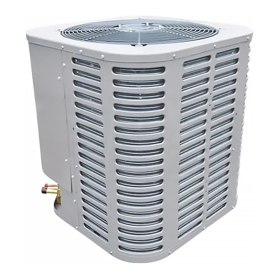
NOTE: Appearance of unit may vary.
RECOGNIZE THIS SYMBOL AS AN INDICATION OF IMPORTANT SAFETY INFORMATION
WARNING
These instructions are intended as an aid to qualified
licensed service personnel for proper installation, adjust-
ment and operation of this unit. Read these instructions
thoroughly before attempting installation or operation.
Failure to follow these instructions may result in improper
installation, adjustment, service or maintenance possibly
resulting in fire, electrical shock, property damage,
personal injury or death.
DO NOT DESTROY THIS MANUAL
Please read carefully and keep in a safe place for future reference by a serviceman.
Advertisement
Table of Contents


Need help?
Do you have a question about the M4AC3018B1000NA and is the answer not in the manual?
Questions and answers