
Related Manuals for Newport 350B


Summary of Contents for Newport 350B
- Page 1 sales@artisantg.com artisantg.com (217) 352-9330 | Visit our website - Click HERE...
- Page 2 Model 350B Temperature Controllers User’s Manual...
- Page 3 We declare that the accompanying product, identified with the mark, complies with requirements of the Electromagnetic Compatibility Directive, 2001/108/EC and the Low Voltage Directive 2006/95/EC. Model Number: Model 350B Series Temperature Controllers Year mark affixed: 2004 Type of Equipment: Electrical equipment for measurement, control and laboratory use...
-
Page 4: Warranty
RESULTING FROM THE PURCHASE OR USE OF ITS PRODUCTS. First printing 2004 © 2004 by Newport Corporation, Irvine, CA. All rights reserved. No part of this manual may be reproduced or copied without the prior written approval of Newport Corporation. - Page 5 The Newport programs and all materials furnished or produced in connection with them ("Related Materials") contain trade secrets of Newport and are for use only in the manner expressly permitted. Newport claims and reserves all rights and benefits afforded under law in the Programs provided by Newport Corporation.
-
Page 6: Technical Support Contacts
Newport Corporation, freight prepaid, clearly marked with the RMA# and the unit will either repaired or replaced at our discretion. Newport is not responsible for damage occurring in transit and is not obligated to accept products returned without an RMA#. - Page 7 This page is intentionally left blank...
-
Page 8: Table Of Contents
Preface Table of Contents EU Declaration of Conformity ............... ii Warranty ....................iii Technical Support Contacts ..............v Table of Contents ..............vii List of Figures and Tables ............ix Safety Precautions Definitions and Symbols ............11 1.1.1 European Union CE Mark ............... 11 1.1.2 Alternating voltage symbol .............. - Page 9 Mounting Considerations ............53 PID Tuning ................55 7.5.1 PID Control Loop ..................55 7.5.2 P Loop ....................56 7.5.3 PI Loop ....................57 7.5.4 PID Loop ....................57 Model 350B Setup ..............58 7.6.1 Model 350B Operating Checklist ............. 58...
- Page 10 Preface Maintenance and Service Enclosure Cleaning ..............61 Fuse Replacement ..............61 Obtaining Service ..............62 Service Form ................63 List of Figures Figure 1 CE Mark ................ 11 Figure 2 Alternating Voltage Symbol ........... 11 Figure 3 On Symbol ..............11 Figure 4 Off Symbol ..............
- Page 11 This page is intentionally left blank...
-
Page 12: Safety Precautions
1.1.1 European Union CE Mark Figure 1 CE Mark The presence of the CE Mark on Newport Corporation equipment means that it has been designed, tested and certified as complying with all applicable European Union (CE) regulations and recommendations. 1.1.2... -
Page 13: Off
350B Temperature Controllers. This symbol represents a Power Off condition. 1.1.5 Fuses Figure 5 Fuse Symbol The fuse symbol in the figure above identifies the fuse location on the Model 350B Temperature Controllers. 1.1.6 Frame or Chassis Figure 6 Frame or Chassis Terminal Symbol... -
Page 14: Protective Conductor Terminal
General Information 1.1.7 Protective Conductor Terminal Figure 7 Protective Conductor Terminal The protective conductor terminal symbol in the above figure identifies the location of the bonding terminal, which is bonded to conductive accessible parts of the enclosure for safety purposes. The intent is to connect it to an external protective earthing system through the power cord. -
Page 15: General Cautions
Follow precautions for static sensitive devices when handling this equipment. This product should only be powered as described in the manual. There are no user-serviceable parts inside the Model 350B Temperature Controllers. To prevent damage to the equipment, read the instructions in the equipment manual for proper input voltage. -
Page 16: Summary Of Warnings And Cautions
Follow directions in section 4.2.4 to properly set tumbler. CAUTION There are no user serviceable parts inside the Model 350B Temperature Controllers. Work performed by persons not authorized by Newport Corporation will void the warranty. For instructions on obtaining warranty repair or service, please refer to Section 8. -
Page 17: Location Of Warnings
Figure 9 Locations of warnings on the rear panel NOTE The Model 350B Temperature Controller is intended for use in an industrial laboratory environment. Use of these products in other environments, such as residential, may result in electromagnetic compatibility difficulties due to conducted as well as radiated disturbances. -
Page 18: General Information
General Information Introduction The intended use of the 350B Temperature Controllers is to precisely control the temperature of a thermo-electric (TE) cooler in a closed loop system using a variety of possible temperature sensors as the feedback. They offer a combination of features, performance, and value that is unmatched by other laser diode temperature controllers. - Page 19 General Information Specifications Model 350B Output Type Bipolar, constant current source TEC Control Loop Type Hybrid P-I-D Maximum Current (A) ±5 Compliance Voltage (V) Available Output Power (W) Accuracy (mA) ±9 Resolution (mA) 0.084 Ripple/Noise (mA rms) <0.03 Current Limit Range (A) 0–5.05...
-
Page 20: Table 1 Specifications Tables
Voltage Requirements ~100/120/220/240 VAC +/-10%, 50–60Hz 325B MAX POWER = 60W Power Requirements 350B MAX POWER = 130W Chassis Ground 4 mm banana jack Size (H x W x D) [in. (mm)] 3.5 (88) x 8.5 (215) x 12.6 (320) Weight [lb (kg)] 8.9 (4.05) -
Page 21: Accessories
General Information Accessories The Model 350B Temperature Controller come with a line cord for connection to AC power. To order accessories use the following part numbers: Model Description 300-02 Temperature Controller Cable 300-04 TEC/Mount Cable 300-16 10.0 kΩ Thermistor (±0.2°C) -
Page 22: Getting Started
Getting Started Unpacking and Handling It is recommended that the Model 350B Temperature Controller be unpacked in a lab environment or work site. Unpack the system carefully; small parts and cables are included with the instrument. Inspect the box carefully for loose parts before disposing of the packaging. -
Page 23: Parts List
Newport Corporation also supplies temperature controlled mounts, lenses, and other accessories. Please consult with a representative for additional information. Parts List The following is a list of parts included with the Model 350B Temperature Controller: 1. User’s manual (CD) and a Printed Copy 2. Power cord 3. -
Page 24: Power Supplies
Getting Started Power Supplies AC power is supplied through the rear panel input power connector that provides in-line transient protection and RF filtering. The input power connector contains the fuses and the switch to select series or parallel connection of the transformer primaries for operation at 100VAC, 120VAC, 220VAC or 240VAC. - Page 25 Getting Started This page is intentionally left blank...
-
Page 26: System Operation
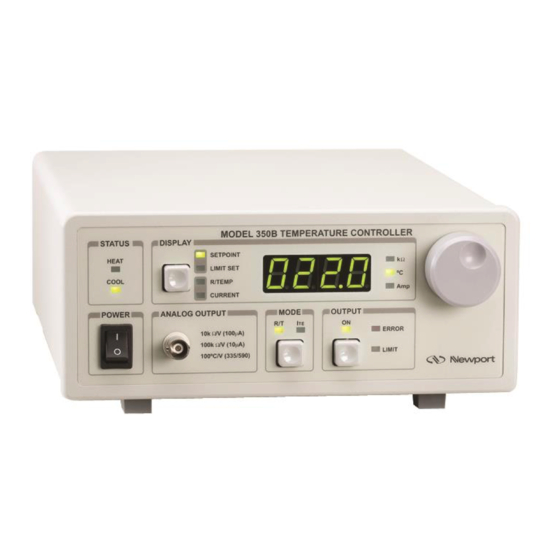
Section 1. Front Panel The front panel of the Model 350B Temperature Controller is arranged for easy operation. Six distinct areas, each with a specific set of related functions, and a control knob are located on the front panel, as shown in Figure 11 below. -
Page 27: Mode Switch
4.1.3 Mode Switch The Model 350B can be operated in either 1) constant R (thermistor resistance), 2) constant T (thermistor), or 3) constant ITE mode. The R/T mode is used with temperature sensors and the ITE mode to maintain a constant output current. If constant T mode is selected and the sensor type is a thermistor, all temperature to resistance conversions are done using the Steinhart-Hart equation. -
Page 28: Control Knob
2) temperature in °C, or 3) output current in Amps. 4.1.7 Control Knob The knob control on the right side of the front panel sets the appropriate reference value corresponding to either resistance (thermistor), temperature (thermistor), or TE current ) to be maintained by the Model 350B Temperature Controller. -
Page 29: Rear Panel
System Operation Rear Panel Figure 12 shows the layout of the rear panel that contains OUTPUT and USB connectors, the sensor select switch, and the AC power inlet. Voltage Setting & Label Fuse Model Number Label Port Sensor Select Table TE Drive Sensor AC Power... -
Page 30: Ac Power Inlet
System Operation 4.2.4 AC Power Inlet The input voltage setting is indicated in a small window on the face of the power module. A small screwdriver is needed to flip down the panel once the AC line cord is removed. Carefully remove plastic tumbler and reinsert it to show the appropriate power grid voltage. - Page 31 System Operation This page is intentionally left blank...
-
Page 32: Computer Interfacing
Computer Interfacing Memory The calibration constants and other temperature controller parameters that must be retained even when the power is removed from the unit are stored in an electrically erasable programmable memory (EEPROM). Commands and Queries There are two types of device commands: commands that cause the instrument to take a desired action, and queries that return a stored value or state of the instrument. - Page 33 Computer Interfacing COMMAND EXECUTION: The controller interprets the commands in the order they are received and execute them sequentially. If a set of commands have to be executed closer to each other, these commands can be sent to the controller simultaneously by creating a command string with semicolon (;) used as a command separator.
-
Page 34: Table 2 Command Summary
Computer Interfacing Commands common to both Temperature Controllers and Laser Diode Drivers: Command Syntax Command Description Remarks *CLS Clear status and response buffer command *IDN? Identification Query *RCL Recall Settings Restore instrument to setup state stored in its non-volatile local memory Reset Instrument *RST Save instrument’s current settings in its non-volatile local... - Page 35 This query will cause the instrument to return an identification string. Controller Model Firmware Firmware Serial # date name version # NEWPORT XXXX vYYY mm/dd/yy, SN ZZZZ Examples: NEWPORT 350B v2.00 05/17/04,SN 1 *RCL Recall command. Description Syntax *RCL value Argument...
- Page 36 Computer Interfacing *SAV Description Save command. *SAV value Syntax Argument Value Description Value Invalid Saves current settings to working settings Saves current settings to user settings Remarks The save command stores the current state of the instrument in non-volatile local memory.
- Page 37 Computer Interfacing ADDRess? Description USB address query. ADDRess? Syntax ADDRess query returns the controller’s USB address. Remarks Response Value Description address Reserved 1 to 99 Valid USB address range See Also ADDRess ERRors? Description Error query. ERRors? Syntax Remarks The ERRors? query returns a list of commands and device errors which have occurred since the last query.
- Page 38 Computer Interfacing COMP VOLTAGE LIMIT ERROR The output has been turned OFF because the forward voltage drop of a TE module exceeds the compliance voltage specified in the Specification table. Once the fault is corrected, “TEC:OUTput 1” command must be issued once to clear the error indication, and a second time to restore current to the TE module.
- Page 39 Computer Interfacing HWTemp? Description Hardware (chassis) temperature query. HWTemp? Syntax Remarks The HWTemp? query returns the value of the hardware temperature measurement. Response Description Measured temperature in C measured temp This measurement is updated approximately once every 225 milliseconds. LOCAL Description Return to local mode (from USB remote) LOCAL...
- Page 40 Computer Interfacing TEC:CONST? Description TEC sensor constants query. TEC:CONST? Syntax Remarks The TEC:CONST? query returns the TEC constants for the Steinhart-Hart equation for thermistors. Response Description See TEC:CONST for a description of these constants. TEC:CONST See Also TEC:GAIN:PID TEC PID controller gain constants command. Description Syntax TEC:GAIN:PID Kp,Ki,Kd...
- Page 41 Computer Interfacing TEC:Ite Description TEC I set point command. TEC:Ite set point Syntax Remarks The TEC:Ite command sets the TEC control current set point. Argument Description set point set point in Amps TEC:Ite?, TEC:LIMit:Ite, TEC:SET:Ite? See Also TEC:Ite? TEC measured I query.
- Page 42 Computer Interfacing TEC:LIMit:Ite? Description TEC ITE current limit query TEC:LIMit:Ite? Syntax Remarks The TEC:LIMit:Ite? query returns the value of the TEC current limit. Response Description limit Limit in Amps See Also TEC:LIMit:Ite TEC:MODE:Ite TEC ITE mode command. Description Syntax TEC:MODE:Ite Remarks The TEC:MODE:Ite command selects TEC constant current mode.
- Page 43 Computer Interfacing TEC:MODE:T Description TEC temperature mode command. TEC:MODE:T Syntax Remarks The TEC:MODE:T command selects TEC constant temperature mode. Since TEC temperature is derived from thermistor or RTD resistance, constant R and T modes are related. In T mode the set point is converted to resistance by using the appropriate constants and conversion model.
- Page 44 Computer Interfacing TEC:OUTput? Description TEC output enable query. TEC:OUTput? Syntax Remarks The TEC:OUTput? query returns the status of the TEC output. Response Value Description enable Although the status of the switch is on, the output may not have reached the set point value. See Also TEC:OUTput TEC:R...
- Page 45 Computer Interfacing TEC:SENsor? Description TEC sensor select query. TEC:SENsor? Syntax Remarks The TEC:SENsor? query returns the sensor type. This value is a coded representation of the sensor type/thermistor current. Refer to the The Steinhart-Hart Equation, Section 7.2.1, for further details. Response Description Thermistor at 100 A drive...
- Page 46 Computer Interfacing TEC:SET:T? TEC temperature set point query. Description Syntax TEC:SET:T? The TEC:SET:T? query returns the TEC constant temperature set point value in C. Remarks Response Description Set point in C set point TEC:T See Also TEC:T Description TEC temperature set point command. TEC:T Syntax The TEC:T command sets the TEC constant temperature set point.
-
Page 47: Software Application
Software Application Overview The 350B/500B Controllers have a USB 2.0 connector on the back of the unit that is used to connect to a computer. This connector will work with USB 1.0 and 1.1 also, as it is fully backwards compatible. -
Page 48: General Usage
Figure 14 Application front panel when communicating (LDD Tab) The software has two tabs, one for the (350B) TEC specific functions, and one for the (500B) LDD functions. The individual TEC and LDD specific tabs have two columns labeled on the top as CONTROLS and READBACK. -
Page 49: Tec Tab
READBACK: Output Enable - Displays output on/off state LD Current - Displays the forward laser current PD Current - Displays the monitor diode (PD) current Bandwidth - Displays the current bandwidth setting 6.3.2 TEC Tab CONTROLS: TEC Mode - Sets R/T/I mode of control Output Enable - Turns on/off the output Temp/R... -
Page 50: Principles Of Operation
Principles of Operation Introduction Three factors must be taken into account when optimizing the operation of a Model 350B Temperature Controller: selection of both the appropriate temperature sensor and TE module heat sink and the manner in which they are mounted. Selecting the proper thermistor to cover a specific temperature range of operation is a simple but important procedure. -
Page 51: The Steinhart-Hart Equation
The rule of thumb is to operate the thermistor near the lower end of its temperature range and use the 100µA current bias. Please contact Newport’s applications engineers if there are any questions regarding the selection of the proper thermistor for an application. -
Page 52: Table Of Constants
Table of Constants Some common thermistors are listed and included the appropriate calibration constants for the temperature range -20 C to 50 C in Table 4. Model 350B, by default, uses the BetaTHERM 10K3A2 thermistor values. Resistance of a 10K, Fenwal UUA41J1 thermistor. -
Page 53: Using Thermo-Electric Modules
Model 350B Temperature Controller is designed to control the rate and amount of cooling or heating through the use of a feedback loop. The arrangement of the TE module in the cooling mode is shown in Figure 16. -
Page 54: Mounting Considerations
TE module will state the maximum current for each TE module and this current value should not be exceeded. The LIMIT SET feature on the Model 350B Temperature Controller allows the user to limit the maximum current flowing through the TE module. -
Page 55: Figure 17 Mounting Arrangement Of A Te Module, Heat Sink And Laser Diode
Two TE modules connected in parallel are shown in the diagram. The actual connection of the TE module depends on the manufacturer’s specifications for the voltage drop across the TE module and its current requirement. Figure 17 Mounting arrangement of a TE module, heat sink and laser diode... -
Page 56: Pid Tuning
TE module (heating/cooling the mount). There are various ways in which the performance of such a control loop can be quantified: settling time, overshoot, etc. In the Model 350B instrument, a PID control algorithm is implemented to achieve optimal stability and settling performance. -
Page 57: P Loop
The following paragraphs explain the PID components and their operation. 7.5.2 P Loop Starting with the simplest type of closed loop control, the P (proportional) loop. The diagram in Figure 19 shows its configuration. Thermo-Electric Temperature (TE) Module Setpoint Temperature Sensor Temperature Controller Figure 19 Proportional Temperature Controller Block Diagram... -
Page 58: Pi Loop
Maintenance and Service 7.5.3 PI Loop To eliminate the small errors that cannot be compensated by P loop alone, an integral term can be added to the control loop. This term integrates (adds) the error continuously and the value, multiplied by the K gain factor, is added to the control signal (Figure 20). -
Page 59: Model 350B Setup
(part #300-02 or #300-04). 7.6.1 Model 350B Operating Checklist The following steps should be followed when operating a Model 350B Series Temperature Controller. Check the AC voltage selection of the unit to be sure that it is compatible with the outlet to be used. - Page 60 During the operation of the Model 350B Temperature Controller any of the parameters may be displayed and the status of the Model 350B Series Temperature Controller may be monitored. NOTE Newport Corporation is not in any way responsible for any damage to any device used in conjunction with the Model 350B.
-
Page 62: Maintenance And Service
Maintenance and Service Maintenance and Service CAUTION There are no user serviceable parts inside the Model 350B Temperature Controller. Work performed by persons not authorized by Newport Corporation will void the warranty. Enclosure Cleaning WARNING Before cleaning the enclosure of the Model 350B Temperature Controller, the AC power cord must be disconnected from the wall socket. -
Page 63: Obtaining Service
2. Instrument serial number (on rear panel) 3. Description of the problem. If the instrument is to be returned to Newport Corporation, a Return Number will be issued, which should be referenced in the shipping documents. Please fill out a copy of the service form, located on the following page, and have the information ready when contacting Newport Corporation. -
Page 64: Service Form
Maintenance and Service Service Form Newport Corporation U.S.A. Office: 800-222-6440 FAX: 949/253-1479 Name _______________________________ Return Authorization #__________________ (Please obtain RA# prior to return of item) Company ________________________________________________________________________ (Please obtain RA # prior to return of item) Address ________________________________ ____________________Date _________________ Country _______________________ Phone Number ______________________________________ P.O. - Page 65 Newport Corporation Worldwide Headquarters 1791 Deere Avenue Irvine, CA 92606 (In U.S.): 800-222-6440 Tel: 949-863-3144 Fax: 949-253-1680 Internet: sales@newport.com Visit Newport Online at: www.newport.com...
Need help?
Do you have a question about the 350B and is the answer not in the manual?
Questions and answers