
Subscribe to Our Youtube Channel
Related Manuals for Newport ILX Lightwave LDT-5910C


Summary of Contents for Newport ILX Lightwave LDT-5910C
- Page 1 User’s Guide Thermoelectric Temperature Controllers LDT-5910C LDT-5940C 70045102 March 2019...
-
Page 3: Table Of Contents
T able of Contents Safety Information and the Manual ................v General Safety Considerations ................... v Safety Symbols ......................vi Safety Marking Symbols ................... vii Warranty ........................vii Limitations ........................ vii Returning an Instrument ..................viii ... - Page 4 Setup .............................. 13 PID Control ............................. 15 Mode ............................... 16 Display ............................16 Error Indicators ..........................17 General Operating Procedures ................. 17 Warm-Up and Environmental Considerations ................17 General Guidelines for Sensor Selection and Safety Limits ............17 ...
- Page 5 Operation Complete Definition .................. 36 Output Off Register ....................38 Command Timing ..................... 39 Sequential / Overlapped Commands ................ 39 Query Response Timing ................... 39 Chapter 4: Command Reference ............... 41 Remote Command Reference Summary ..............41 ...
- Page 6 March 2019 LDT-5910C and LDT-5940C...
-
Page 7: Safety Information And The Manual
Safety and Warranty Information Details about cautionary symbols Safety markings used on the instrument Information about the warranty Customer service contact information Safety Information and the Manual Throughout this manual, you will see the words Caution and Warning indicating potentially dangerous or hazardous situations which, if not avoided, could result in death, serious or minor injury, or damage to the product. -
Page 8: Safety Symbols
Safety Symbols This section describes the safety symbols and classifications. Technical specifications including electrical ratings and weight are included within the manual. See the Table of Contents to locate the specifications and other product information. The following classifications are standard across all ILX Lightwave products: ... -
Page 9: Safety Marking Symbols
Safety Marking Symbols This section provides a description of the safety marking symbols that appear on the instrument. These symbols provide information about potentially dangerous situations which can result in death, injury, or damage to the instrument and other components. Visible and/or Caution, refer Earth ground... -
Page 10: Returning An Instrument
Returning an Instrument If an instrument is to be shipped to ILX Lightwave for repair or service, be sure to: Obtain a Return Authorization number (RA) from ILX Customer Service. Attach a tag to the instrument identifying the owner and indicating the required service or repair. -
Page 11: Comments, Suggestions, And Problems
Comments, Suggestions, and Problems To ensure that you get the most out of your ILX Lightwave product, we ask that you direct any product operation or service related questions or comments to ILX Lightwave Customer Support. You may contact us in whatever way is most convenient: Phone (800) 459-9459 or (406) 586-1244 (406) 586-9405 On the web at: ilx.custhelp.com... - Page 12 March 2019 LDT-5910C and LDT-5940C...
-
Page 13: Chapter 1: Introduction And Specifications
Chapter 1: Introduction and Specifications This chapter is an introduction to the LDT-5910C and LDT-5940C Thermoelectric Temperature Controllers. Safety Considerations and unpacking information Product Overview Options and accessories Specifications Safety Considerations If any of the following symptoms exist, or are even suspected, remove the LDT-5910C or LDT-5940C from service. -
Page 14: Product Overview
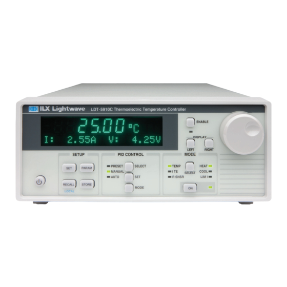
Product Overview The LDT-5910C and LDT-5940C are high performance thermoelectric temperature controllers that offers a flexible, extended temperature control range from -100 °C to +200 °C with a choice of temperature sensors. The LDT-5910C features a linear, bipolar output providing 32 Watts of power to drive most thermal loads. - Page 15 Figure 1.1 – LDT-5910C and LDT-5940C Front Panel Figure 1.2 – LDT-5910C Rear Panel March 2019 LDT-5910C and LDT-5940C...
- Page 16 Figure 1.4 – LDT-5940C Rear Panel March 2019 LDT-5910C and LDT-5940C...
-
Page 17: Options And Accessories
Options and Accessories Options and accessories available for LDT-5910C and LDT-5940C Thermoelectric Temperature Controllers include the following: DESCRIPTION MODEL / PART NUMBER Single Rack Mount Kit RM-144 Dual Rack Mount Kit RM-145 Temperature Controller Interconnect Cable (terminated with 9-pin DSUB) CC-505S [5910C only] Temperature Controller Interconnect Cable (unterminated) -
Page 18: Specifications
Specifications March 2019 LDT-5910C and LDT-5940C... - Page 19 March 2019 LDT-5910C and LDT-5940C...
- Page 20 March 2019 LDT-5910C and LDT-5940C...
-
Page 21: Chapter 2: General Operation
Chapter 2: General Operation This chapter is an overview of the operation of the LDT-5910C and LDT-5940C Thermoelectric Temperature Controllers. Power requirements Front panel operation General operating procedures Grounding Requirements The LDT-5910C and LDT-5940C Thermoelectric Temperature Controllers come with a three conductor AC power cable. -
Page 22: Firmware Upgradeability
During the front panel indicator test, the LDT-5910C and LDT-5940C performs a self-test to ensure that the internal hardware and software are communicating. If the LDT-5910C and LDT-5940C cannot successfully complete the test, an error message is displayed. See Chapter 5 for a complete list of error messages. -
Page 23: Connections
Connections Temperature Control Output: A 15-pin DSUB connector (5910C) or 25-pin DSUB connector (5940C) is located on the back panel of the instrument. The connections for each case are shown below. LDT-5910C LDT-5940C PIN NUMBER CONNECTION PIN NUMBER CONNECTION TE Module (+) Sensor (+) Sense Terminal TE Module (+) Sensor (-) Sense Terminal... - Page 24 Interlocks: The LDT-5910C and LDT-5940C have normally open and normally closed interlock contacts. The interlock will change states from the “powered off” condition when the output is enabled and will change back when the output is disabled; including any error condition that disables the output.
-
Page 25: Front Panel Operation
Front Panel Operation This section describes the fundamentals of operation for the LDT-5910C and LDT-5940C Thermoelectric Temperature Controllers. The order of descriptions will follow the normal progression of how the user would typically configure the instrument for use for the first time. Figure 2.1 –... - Page 26 PARAM Button Uses a menu system for temperature controller setup functions including Limits, – Sensor, Sensor Calibration Constants, External Fan Control, Cable Resistance, Analog Input, GPIB Address, and Display Brightness. The SET button selects each menu item and a second SET press allows the user to adjust each parameter.
-
Page 27: Pid Control
RECALL Button – Recalls instrument parameters for control mode, setpoint, limits, sensor type, calibration constants, and PID values for bins numbered 1 – 10. Recall bin 0 will reset all parameters to the factory defaults. Non-volatile memory is used for saving the instrument parameters. When a store operation is performed, all of the current instrument parameters are stored to a "bin"... -
Page 28: Mode
Auto-tune – The auto-tune mode will calculate a thermal system's PID coefficients through an iterative PID temperature control process. To enter the auto-tune mode first press MODE until the AUTO LED is illuminated, and then SET to begin the auto-tune procedure. -
Page 29: Error Indicators
Figure 2.2 a – The measured current Figure 2.2 b – The setpoint current LEFT Button – Cycles through available measurement and setpoint parameters that can be displayed in the left hand side of the display. RIGHT Button – Cycles through available measurement and setpoint parameters that can be displayed in the right hand side of the display. - Page 30 In constant temperature mode, the quantity that is maintained constant by the controller is the sensor resistance. In constant temperature mode (T), the LDT-5910C and LDT-5940C convert the temperature setpoint to a thermistor resistance setpoint using user defined constants. The Steinhart-Hart equation is used to convert a temperature to a resistance for thermistor sensors.
- Page 31 Notice also that the lower slope of the curve at the higher temperatures results in a smaller feedback signal. It may be necessary, if you are controlling to higher temperatures, to use a thermistor with a different curve. Figure 2.3 - Example Thermistor Resistance vs. Temperature LINEARIZED THERMISTOR - The linearized thermistor mode of the LDT-5910C and LDT- 5940C may be used when an expanded range of temperature operation is required but when ranging discontinuities are unacceptable.
- Page 32 1.40 1.20 10K Thermistor / 100 uA Bias 10K Thermistor / Linearized 1.00 0.80 0.60 0.40 0.20 0.00 Temperature (C) IC-I SENSORS – When an IC-I sensor is selected, the LDT-5910C and LDT-5940C measures temperature based on the current passed through the sensor. An example of an IC-I sensor is the Analog Devices AD590.
- Page 33 The sensor will have approximately 1 mA of current through it at all times. In IC-V sensor mode, the LDT-5910C and LDT-5940C have a sensor voltage limit of 6 V, which is approximately 325 °C. RTD SENSORS – When an RTD sensor is selected, the LDT-5910C and LDT-5940C measures temperature based on the resistance.
-
Page 34: Safety Limits
For optimal accuracy and stability, the 1 mA current source should be selected for RTD sensors with resistance of 200 Ω to 1500 Ω and the 2.5 mA range should be used with resistance of 1 Ω to 200 Ω. In general, the change in resistance per change in temperature is much lower for a typical 100 Ω... - Page 35 2. Turn on the LDT-5910C or LDT-5940C. The output will be disabled at power up and the unit will automatically configure its parameters to the state which existed when the power was last shut off 3. Press MODE until SNSR is selected 4.
-
Page 36: Constant Current Mode Operation
Constant Current Mode Operation 1. Plug the LDT-5910C or LDT-5940C into an AC power source supplying the correct mains voltage and frequency for your instrument (refer to the rear panel for the correct ratings) 2. Turn on the LDT-5910C or LDT-5940C. The output will be disabled at power up and the unit will automatically configure its parameters to the state which existed when the power was last shut off 3. -
Page 37: Chapter 3: Remote Operation
Chapter 3: Remote Operation This chapter is an overview of the remote operation of the LDT-5910C and LDT-5940C Thermoelectric Temperature Controller. Fundamentals of Remote Operation Command Syntax Command Tree Structure Status Reporting Test and measurement equipment with remote operation capability will generally communicate through either GPIB or USB interfaces. -
Page 38: Talkers, Listeners, And Controllers
addressing or un-addressing devices. In addition, some individual bus lines are designated for this purpose. Talkers, Listeners, and Controllers Every GPIB system consists of one or more “talkers” and “listeners”, and often at least one “controller”. Talkers supply data while listeners accept data. A system can consist of simply a talker and listener, for example a meter connected to a datalogger or chart recorder. -
Page 39: The Gpib Connector
The GPIB Connector The standard GPIB connector consists of 16 signal lines in a 24-pin stackable connector. The extra pins are used to make twisted pairs with several of the lines. There are eight data input/output lines, three handshake lines, and five interface management lines. Eight data I/O (DIO) lines carry both data (including device dependent commands) and interface messages. -
Page 40: Reading The Gpib Address
Reading the GPIB Address Before operating the LDT-5910C or LDT-5940C remotely, its GPIB address must be known. Simply press the PARAM button until GPIB Address is displayed in the display. The factory default address is “GPIB ADDRESS: 1”. Changing the GPIB Address Every device on the GPIB bus must have a unique address. -
Page 41: Changing Between Local And Remote Operation
Changing Between Local and Remote Operation Sending a command over the GPIB or USB bus automatically puts the instrument in Remote mode. The Remote indicator identifies when the controller is in remote operation mode. When the instrument is in Remote mode, all front panel controls are disabled except for the Local button. Pressing the Local button returns the instrument to Local control mode. -
Page 42: White Space
White Space “White space” is normally the space character (space bar). A single white space must separate a command from its parameters or data. For example: Table 3.2 – White Space ACCEPTABLE NOT ACCEPTABLE ITE 3.0 ITE3.0 To enhance readability, one or more white spaces may be used before a comma, semicolon, or terminator. -
Page 43: Parameters
Parameters Some commands require a parameter. The parameter must be separated by at least one white space. The syntax symbol <nrf value> refers to the flexible numeric representation defined by the GPIB standard. It means that numbers may be represented in integer or floating point form, or in engineering/scientific notation. -
Page 44: Command Tree Structure
Command Tree Structure The LDT-5910C and LDT-5940C Thermoelectric Temperature Controllers device-dependent commands are structured in a tree format as shown in Figure 3.3. Each of the legal paths is shown, followed by its list of path options, followed by the commands themselves. It is recommended that the first-time user begin learning the commands by using the full path notation. -
Page 45: Syntax Summary
Syntax Summary GPIB commands must contain all of the letters shown in uppercase in the command definition. Optional letters shown in lowercase for some device dependent commands in the command reference (Chapter 4) are useful for clarity, but must be in the correct sequence. A single white space must separate a command from its parameters or data. -
Page 46: Ieee 488.2 Common Commands
IEEE 488.2 Common Commands The IEEE 488.2 Common Commands and Queries are distinguished by the “*” which begins each mnemonic. The diagrams below show the syntax structure for common commands, common command queries, and common commands with numeric data required. Figure 3.4 –... -
Page 47: Status Reporting
Table 3.7 – IEEE 488.2 Common Commands Supported by LDT-5910C and LDT-5940C *CLS *ESE *ESE? *ESR? *IDN *OPC *OPC? *PSC *PSC? *RCL *RST *SAV *SRE *SRE? *STB? *TST? *WAI See Chapter 4 – Command Reference for descriptions of all commands, including common commands, supported by the LDT-5910C and LDT-5940C. - Page 48 Figure 3.5 – Status Reporting Scheme March 2019 LDT-5910C and LDT-5940C...
-
Page 49: Operation Complete Definition
Operation Complete Definition Note that Bit 0 of the Standard Event Status Register contains the status of the Operation Complete flag. Enabling this bit via the *ESE command allows the user to update Bit 5 of the Status Byte. Then, if the SRE mask has Bit 5 set, and the user issues an *OPC command, the SRQ signal will be generated upon completion of the currently processed commands. -
Page 50: Output Off Register
Output Off Register The Output Off Enable Register determines which conditions and events can cause the TEC output to be turned off. This register is configured in a manner which is similar to the status reporting registers. However, its output is not reported in the Status Byte Register. Rather, it is directly tied to hardware which controls the output switching. -
Page 51: Command Timing
Command Timing This section describes, for each device-dependent command, whether that command is performed in an overlapped or sequential manner. In other words, it states whether the next command may begin while the first is being executed, or if it must wait until the first command is completed before its execution begins. - Page 52 March 2019 LDT-5910C and LDT-5940C...
-
Page 53: Chapter 4: Command Reference
Chapter 4: Command Reference This chapter is a guide to all of the device-dependent commands for the LDT-5910C and LDT- 5940C Precision Thermoelectric Temperature Controllers. This chapter is divided into three parts. Overview of the remote commands List of remote commands in alphabetical order ... - Page 54 Table 4.2 – Instrument Specific Command Summary Reference List NAME FUNCTION Determines whether temperature modulation is :ANAloginput ON|OFF|1|0 enabled via the analog in BNC. :CABLER <ohms> Output Cable Resistance setting COND? Queries device conditions. Gain and Offset for temperature to current CONST:ICI <slope>,<offset>...
- Page 55 NAME FUNCTION PID <P>,<I>,<D> Temperature Control Loop PID constants PID:ATUNE RUN|STOP Auto PID Tuning returns (IDLE|RUNNING|PASS|FAIL) PID:PRESET <Name> Stored PID Presets RADix Returned integer format BINary|DECimal|HEXadecimal|OCTal SENsor ICI|ICV|THERM10UA|THERM100UA| Temperature sensor selection THERMAUTO|THERMLINEAR|RTD1MA|RTD2_5MA SET:ITE <amps> TEC Current Setpoint (ITE mode) SET:SENsor <value> Sensor Control Setpoint (sensor mode) SET:Temp <degrees>...
-
Page 56: Ldt-5910B Compatibility For Ldt-5910C
LDT-5910B Compatibility for LDT-5910C To enable compatibility from the 5910B send SYNTAX 0. The following commands are provided for compatibility with software written for the 5910B: :COND? :CONST ITE? RADix :CONST? :LIMit:ITE RADix? :DEC :LIMit:ITE? SET:R? :ENABle:COND :LIMit:THI SET:T? :ENABle:COND? :LIMit:THI? SENsor? :ENABle:EVEnt... -
Page 57: Command Reference
Command Reference The following pages contain a reference for common commands of the LDT-5910C and LDT-5940C Thermoelectric Temperature Controllers. *CLS Clear Status Description Clears all status event registers and the error queue Notes Useful to clear registers before enabling service requests (SRQ) Examples *CLS *ESE <integer>... - Page 58 *ESR? Standard Event Status Register Query Description Determine the contents of the standard event status register Parameters None Notes Reading this register clears the contents. The response is a value between 0 and 255, representing the bits of the standard event status register when expressed in base 2 binary format. The event bit is set when a specific event occurs: ...
- Page 59 *OPC Operation Complete Description Sets the operation complete bit (bit 0) in the standard event status register when all pending overlapped commands have been completed Parameters None Notes This command does not hold off subsequent operations. You can determine when the overlapped commands have completed either by polling the standard event status register (*ESR?) or by setting up the status system such that a serve request is asserted when bit 0 is set in the standard event status register.
- Page 60 *PSC? Power-on Status Clear Query Description Requests the status of the power-on status clear flag Parameters None Notes Response: 0 – The enable registers are saved through power off/on. 1 – The enable registers are cleared during power on. Registers affected: Condition Status Enable Service Request Enable Event Status Enable...
- Page 61 *SAV <bin> Save Description Saves the current instrument configuration to non-volatile memory Parameters A value from 1 – 10 Notes The *SAV operation saves the contents of everything affected by the *RST command. It is not necessary to save the current setup for next power-on. The current setup is automatically stored and recall at next power-on. Use *RCL <bin>...
- Page 62 *SRE? Service Request Enable Query Description Returns the enabled bits in the service request enable register Parameters None Notes The response is a value between 0 and 255, representing the bits of the standard event status enable register when expressed in base 2 binary format Examples “*SRE?”...
- Page 63 *WAI Wait to Continue Description Prevents the instrument from executing any further commands until all pending operations are complete Parameters None Notes This command can be used to make the instrument wait until an operation is complete before continuing Care should be taken to set the time-out appropriately for use with the *WAI command. After this command is sent, the instrument may block subsequent commands waiting for the input queue to empty.
- Page 64 The following pages contain a reference for device-dependent commands of the LDT-5910C and LDT-5940C Thermoelectric Temperature Controllers. :ANAloginput ON|OFF|1|0 :ANAloginput? Description Enables the analog input rear panel BNC to be used for temperature modulation. Parameters ON/1 – Temperature Modulation ON OFF/0 –...
- Page 65 :CONST:ICV <slope>,<offset> :CONST:ICV? Description Slope and offset compensation for a temperature to voltage transducer. Parameters slope – 0 to 99.99 representing the mV/K response of the temperature to current transducer. offset – -99.99 to 99.99 representing the sensor offset in mV Reset Value 10, 0 CONST:ICV:SLOPe <mV/K>...
- Page 66 :CONST:THERMistor <C1>,<C2>,<C3> :CONST:THERMistor? Description Steinhart-Hart parameters for a thermistor temperature transducer. Parameters -9.9999 to 9.9999 representing the first parameter of the Steinhart-Hart equation multiplied by 10 -9.9999 to 9.9999 representing the second parameter of the Steinhart-Hart equation multiplied by 10 -9.9999 to 9.9999 representing the third parameter of the Steinhart-Hart equation multiplied by 10 Notes The Callendar-Van Dusen equation:...
- Page 67 :ENABle:COND <integer> :ENABle:COND? Description Enables bits in the device condition status enable register. Parameters 0 to 65535 Notes Enabled/disabled conditions can be set by ENABle:COND?. Changing condition status may be monitored by COND?. See Chapter 3 for more information about register structure. Examples ENAB:COND? - Response 1 means that over current limit will be reported in status byte bit 3.
- Page 68 See Chapter 3 for more information about register structure. Enable registers normally retain their values through power OFF/ON, unless the power-on status clear flag is set true. See *PSC. Examples ENAB:EVE 64 - Enables Sensor Open event to be summarized in the status byte bit 2. Enable:event #H40 - Same as ENAB:EVE 64, except using hexadecimal numbering.
- Page 69 Notes Enabled/disabled events can be set by ENABle:EVEnt. Status bits are set by events, and cleared when read or cleared by command. See *CLS and EVEnt? commands. See Chapter 3 for more information about register structure. Examples EVE? - Response 2048 means that cal ready events occurred since the last EVE? inquiry. Event? - Response #H800 is the same as 2048, except using hexadecimal numbering.
- Page 70 :LIMit:ITE:HIgh <amps> :LIMit:ITE:HIgh? Description Upper TEC current limit Parameters Amps – Output current is clipped below this value in all control modes. Notes Use inconjunction with :LIMit:ITE:LOw to control the limit. An error will be generated for a setpoint lower than the LOW limit.
- Page 71 :LIMit:Temp:HIgh <degrees> :LIMit:Temp:HIgh? Description Sets the more positvie temperature at which the temperature controller will turn off. Parameter Degrees – maximum temperature at which the controller will shut off. Notes Only used in T mode. Reset Value Examples LIM:T:HI 105.0 action: sets the high temperature limit to 105.0 ºC. :LIMit:Temp:LOw <degrees>...
- Page 72 Response Ohms - Resistance when using a thermistor or RTD. µA and V when using ICI and ICV sensors respectively. Notes The response is the measured sensor, regardless of control mode, and the units are dependent upon which sensor is selected. For thermistor or RTD, the value will be in ohms, ICI in MicroAmps, ICV in Volts. Examples MEAS:SEN? response: 0.0001323 means the measured sensor value is 132.3 μA, (if instrument sensor is set for ICI).
- Page 73 Notes The output on bit 10 in the event or condition status register can be used to determine the actual point that the output is turned on, or if it has automatically shut off due to an error condition. Additionally, *OPC? Or *WAI may be used to determine the time when the output reaches setpoint.
- Page 74 Notes The 5910B compatible gains are called with GAIN# where # is the gain number for the 5910B. For preset mounts the syntax is the model name of the mount without dashes, i.e. LDM4405 is the preset constnants for an LDM-4405. The response includes each preset value in quotes.
- Page 75 :SENsor <name> :SENsor? Description Sensor selection for temperature conversion and for use in sensor mode. Parameters ICI – Temperature to current transducer, i.e. AD590 ICV – Temperature to voltage transducer, i.e. LM335 THERM10UA – Thermistor with a 10 uA current source, Good for resistance > 450 kΩ. THERM100UA –...
- Page 76 :COND? :STATus? Description Requests the contents of the device condition status register. Response A value between 0 and 65535 Notes The conditions reported to the status byte are set through the ENABle:COND command. The condition status may be constantly changing, while the event status is only cleared when it is cleared or read.
-
Page 77: Chapter 5: Calibration And Troubleshooting
Chapter 5: Calibration and Troubleshooting This chapter is to help you resolve any problems you may experience with your LDT-5910C and LDT-5940C quickly. If you need additional help, please contact ILX Lightwave Customer Service. See page viii for contact information. ILX Lightwave Corporation provides in-house calibration services for ILX instruments. -
Page 78: Troubleshooting Guide
Troubleshooting Guide This section lists some common problems and corrective actions. In the event that the corrective action does not resolve problem; please contact ILX Lightwave. For a comprehensive list of frequently asked questions, see the ILX Lightwave website or contact ILX Lightwave Customer Service (see Comments, Suggestions, and Problems on page viii for contact information). - Page 79 PARAM menu confirm the appropriate Sensor has been selected. If the problem persists contact customer support. Power on, but temperature is not If there is a SENSOR OPEN indication (Error code 505), controlled or is unstable. check the sensor connections (pins 14,15). Check that the proper sensor current range is selected.
- Page 80 re-connect one instrument at a time until the problem returns. Then check the other instrument for address conflicts and proper GPIB function. Read the error queue remotely (ERR?). The command syntax or command structure may be in error. Read the status byte (*STB?) and condition register (COND?) for possible device problems.
-
Page 81: Error Messages
Error Messages Error messages may appear on the LDT-5910C and LDT-5940C display when error conditions occur in the instrument. In remote operation, use ERR? to read the current error list. The ERR? command returns a string containing up to 10 of the error messages that are currently in the error message queue. - Page 82 Table 5.5 - Instrument Specific Errors ERROR CODE EXPLANATION Over temperature limit Over sensor limit Over current limit TEC open Sensor open Autotune failure Calibrate sensor in thermistor auto mode Internal communication error (the instrument needs to be returned to ILX) March 2019 LDT-5910C and LDT-5940C...
-
Page 83: Calibration Overview
Calibration Overview The LDT-5910C and LDT-5940C Thermoelectric Temperature Controllers should be calibrated every 12 months or whenever performance verification indicates that calibration is necessary. All calibrations can be done with the case closed. The instrument is calibrated by changing the internally stored digital calibration constants. -
Page 84: Thermistor Calibration
Thermistor Calibration The following procedure calibrates the 100 µA or 10 µA constant current sources so that thermistor resistance measurements will be accurate. This procedure does not calculate C1, C2, and C3. For information on calibrating the thermistor sensor, see Application Note #4 Thermistor Calibration and the Steinhart-Hart Equation. -
Page 85: Ic-I (Ad590 Or Equivalent) Sensor Calibration
8. Press and hold in the parameter SET button and turn the ADJUST knob until the display indicates the same resistance calculated in step 7. 9. Reconnect the 12 kΩ resistor and measure the voltage across the resistor. 10. Disconnect the DMM. 11. -
Page 86: Rtd Sensor Calibration
3. Enter the sensor calibration mode by pushing the parameter RECALL and mode SELECT buttons at the same time. 4. Press and hold in the parameter SET button and turn the ADJUST knob until the display indicates the same voltage as shown on the precision voltmeter. 5. - Page 87 3. Press and hold in the parameter SET button and turn the ADJUST knob until the display shows the absolute value of the ITE measurement as calculated from step 2. 4. Release the SET button. Wait three seconds to allow the ITE current to settle at -3 Amps.
-
Page 88: Tec Voltage Measurement Calibration
TEC Voltage Measurement Calibration The following procedure calibrates the TEC voltage measurement. 1. Calibrate the ITE current as described in the section above. 2. Measure the exact resistance of a 5 Ω, 25 W resistor 3. With the output off, connect the resistor across the TEC output terminals of the LDT- 5910C (pins 1 and 3) of the 15-pin connector or the LDT-5940C (pins {9, 10, 21, 22} and {12, 13, 24, 25}) of the 25-pin connector. -
Page 89: Appendix A: Ad590 And Lm335 Sensor Calibration
Appendix A: AD590 and LM335 Sensor Calibration The LDT-5910C and LDT-5940C Thermoelectric Temperature Controllers use two constants (slope and offset) for calibrating linear IC thermal sensing devices, such as the AD590, and the LM335. Offset is used as the linear or zero offset value, and the slope is used as the slope or gain adjustment. -
Page 90: Lm335 Sensor
temperature error associated with the device. This non-linearity is shown in Figure A.1, reprinted from Analog Devices specifications, where the error associated with C1 is assumed to be zero. Figure A.1 If a maximum absolute error of 0.8 °C is tolerable (over the entire temperature range), the one point calibration of C1 should be used. -
Page 91: One Point Calibration Method
case, the temperature accuracy is typically ±1 °C over the rated operating range. With C1 and C2 calibrated also, the temperature accuracy is typically ±0.3 °C over the rated operating range. The temperature accuracy may be improved over a narrow temperature range by a two-point calibration of C1 and C2. - Page 92 3. Place the sensor at an accurately known and stable temperature, Ta1. Connect the sensor to pins 7 and 8 of the LDT-5910C 15-pin connector or to pins 14 and 15 of the LDT-5940C 25-pin connector. Set the LDT-5910C or LDT-5940C for normal constant temperature (T mode) operation.
-
Page 93: Appendix B: Auto-Tune Method
Appendix B: Auto-Tune Method The LDT-5910C and LDT-5940C Thermoelectric Temperature Controllers currently use a single auto-tune method. The auto-tune algorithm will calculate a thermal system's appropriate PID coefficients through an iterative PID temperature control process. The figure below describes the tuning process pictorially. The auto-tune algorithm starts controlling temperature (Point 2 on graph) with an arbitrary coefficient for the loop gain (P term), and slowly increases it until the temperature begins to oscillate. - Page 94 around the user defined tuning setpoint (Point 7 on Graph). The final I term coefficient is set to 33% of the I term value that is found to start oscillations in the temperature control loop. This tuning method calculates PID coefficients that result in fast settling times and good setpoint stability.
Need help?
Do you have a question about the ILX Lightwave LDT-5910C and is the answer not in the manual?
Questions and answers