Table of Contents
Advertisement
Quick Links
O
P
E
R
A
O
P
E
R
A
TH2638/A
P P
r r
e e
c c
i i
s s
i i
o o
P
r
e
c
i
s
i
o
C C
h h
a a
n n
g g
z z
h h
o o
u u
T T
o o
C
h
a
n
g
z
h
o
u
T
o
A A
d d
d d
: : No.3, Tianshan Road, New District, Changzhou, Jiangsu
A
d
d
:
( (
T T
e e
l l
: :
(
0 0
5 5
1 1
9 9
T
e
l
:
0
5
1
( (
) )
F F
a a
x x
: :
(
0 0
5 5
1 1
9 9
)
F
a
x
:
0
5
1
9
E E
- -
m m
a a
i i
l l
: :
S S
E
-
m
a
i
l
:
S
W W
e e
b b
s s
i i
t t
e e
: :
h h
t t
t t
W
e
b
s
i
t
e
:
h
t
t
T
I
O
N
M
A
T
I
O
N
M
A
n n
C C
a a
p p
a a
c c
i i
t t
a a
n n
c c
e e
M M
n
C
a
p
a
c
i
t
a
n
c
e
M
n n
g g
h h
u u
i i
E E
l l
e e
c c
t t
r r
o o
n n
n
g
h
u
i
E
l
e
c
t
r
o
n
) )
, ,
)
8 8
5 5
1 1
9 9
5 5
5 5
6 6
6 6
,
8 8
5 5
1 1
3 3
2 2
2 2
9
8
5
1
9
5
5
6
6
8
5
1
3
2
8 8
5 5
1 1
0 0
9 9
9 9
7 7
2 2
8
5
1
0
9
9
7
2
a a
l l
e e
s s
@ @
t t
o o
n n
g g
h h
u u
i i
. .
c c
o o
m m
. .
c c
n n
a
l
e
s
@
t
o
n
g
h
u
i
.
c
o
m
.
c
n
p p
: :
/ /
/ /
w w
w w
w w
. .
t t
o o
n n
g g
h h
u u
i i
. .
c c
o o
m m
. .
p
:
/
/
w
w
w
.
t
o
n
g
h
u
i
.
c
o
m
N
U
A
L
N
U
A
L
e e
t t
e e
r r
e
t
e
r
i i
c c
C C
o o
. .
, ,
L L
t t
d d
. .
i
c
C
o
.
,
L
t
d
.
2 2
2 2
2
2
2
c c
n n
.
c
n
Advertisement
Table of Contents

Related Manuals for Changzhou Tonghui Electronic TH2638/A

Summary of Contents for Changzhou Tonghui Electronic TH2638/A
- Page 1 TH2638/A : : No.3, Tianshan Road, New District, Changzhou, Jiangsu ( ( ) ) , , ( ) , ( ( ) ) ( )...
-
Page 2: Table Of Contents
TH2638/A Operation Manual Ver1.1 Contents Chapter 1 Out of Box Audit ......................1 To Inspect the package ....................1 Power connection ......................1 Fuse ..........................1 Environment ......................... 1 Use of Test Fixture ....................... 2 Warm-up ........................2 Other features ....................... 2 Chapter 2 Introduction ........................ - Page 3 TH2638/A Operation Manual Ver1.1 4.14 Configuration of limit table beep ................32 4.15 BEEPER ........................32 4.16 BEEPER TONE ......................33 4.17 LANGUAGE ......................33 4.18 PASS WORD ......................34 4.19 TALK ONLY ......................34 4.20 BAUD RATE ......................34 4.21...
- Page 4 TH2638/A Operation Manual Ver1.1 6.2.2 Selecting an appropriate measurement range ..........53 6.2.3 Using correction function ................54 6.2.4 Improving measurement stability ............... 54 6.2.5 Using a four-terminal pair in measurement ..........54 6.2.6 Using frequency shift ................. 54 Tips for higher measurement speed ................54 6.3.1...
- Page 5 TH2638/A Operation Manual Ver1.1 Announcement The description of the manual may not cover all contents of the instrument, and our company is subject to change and to improve the performance, function, inner structure, appearance, accessory and package of the instrument without notice. If there is puzzle caused by inconsistency of manual...
-
Page 6: Chapter 1 Out Of Box Audit
Chapter 1 Out of Box Audit When you receive the instrument, some inspections are necessary, and the condition must be understood and available before installing the instrument. 1.1 To Inspect the package Inspect the shipping container for damage after unpacking it. It is not recommended to power on the instrument in the case of a damaged container. -
Page 7: Use Of Test Fixture
keep good airiness, please don’t obstruct the left and right airiness holes to make the instrument maintain the accuracy. Although the instrument has been specially designed for reducing the noise caused by ac power, a place with low noise is still recommended. If this cannot be arranged, please make sure to use power filter for the instrument. -
Page 8: Chapter 2 Introduction
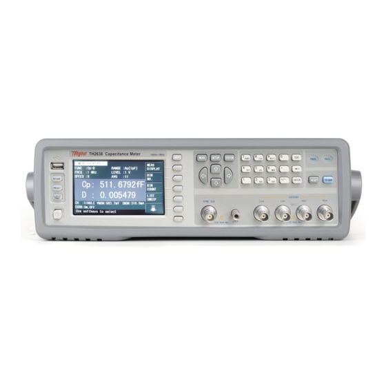
Chapter 2 Introduction In this chapter, the basic operation procedures and names & functions of the front panel, rear panel as well as screen display of TH2638 are described. Product Introduction TH2638 is a capacitance meter for ceramic capacitor production tests. It can be used for evaluating ceramic capacitance at frequencies 100Hz, 120Hz, 1kH, 10 kHz, 40 kHz, 100 kHz, 1 MHz and test signal levels (0.1 V to 1 V). - Page 9 Brand and model Brand and model. [COPY] Press this key to save the screen shot of test result to USB disk. [MEAS] Press this key to enter into the measurement result display page. [SETUP] Press this key to set the measurement conditions, limit values of correction, list setup, file setup and contact check function.
- Page 10 14) UNKNOWN terminals These are the UNKNOWN terminals used to connect a four-terminal pair test fixture or test leads for measuring the device under test (DUT). NOTE: When using a four-terminal pair test fixture or test leads with a stopper, remove the stopper or the bumper of TH2638.
-
Page 11: Introduction To Rear Panel
24) [KEYLOCK] Press [KEYLOCK], it will be lighted, which means the function of current panel is locked. Press it again, it will be off, which means discharging the lock status. If the password function is ON, it means correct password is necessary when discharging the key-lock, or the key cannot be unlocked. -
Page 12: Fan
GPIB interface General Purpose Interface Bus (GPIB). The connection of an external controller and other devices through this connector allows you to configure an automatic measurement system. Scanner interface The interface to connect a scanner can perform up to 256 sets of multi-channel corrections and measurements. - Page 13 Figure 2-3 display zones Display page name Indicate the name of the currently displayed page. Soft keys The zone is used to display the function definition of soft key. A displayed to the right of a softkey indicates that pressing ↓ will display the softkey label one level lower.
-
Page 14: Basic Operation
2.5 Basic Operation Basic operation of TH2638 is as follows: Use [MEAS] keys and soft keys to select the desired page. Use cursor keys ([←][→] [↑] [↓]) to move the cursor to the desired zone. When the cursor moves to a specified zone, the zone will become reverse expression. -
Page 15: Chapter 3 Basic Measurement Procedure
Chapter 3 Basic Measurement Procedure This chapter describes the procedure to measure a capacitor with the test fixture by using TH2638. 3.1 Connecting test fixture Generally, it is difficult to connect the DUT (capacitor) directly to the TH2638. Therefore, a test fixture is generally used to connect the DUT to the TH2638. - Page 16 Primary parameter Secondary parameter D, Q, G, Rp D, Q, Rs, Rs – Ls Each parameter is described below. Capacitance value measured by parallel equivalent circuit model Capacitance value measured by series equivalent circuit model Dissipation factor Quality factor (inverse of D) Equivalent parallel conductance measured by parallel equivalent circuit model Equivalent parallel resistance measured by parallel equivalent circuit model Equivalent series resistance measured by series equivalent circuit model...
- Page 17 Figure 3-1 Primary parameter selection menu screen Step 4: Press the softkey to select the secondary parameter (as shown in Figure 3-2) Figure 3-2 Secondary parameter selection menu screen Setting up measurement signal frequency Set up the frequency of the signal applied to the DUT (capacitor) during measurement. Step 1: Press [MEAS] key.
- Page 18 Figure 3-3 Measurement signal frequency selection menu screen Setting up measurement signal level Set up the voltage level of the signal applied to the DUT (capacitor) during measurement. Step 1: Press [MEAS] key. Step 2: Move the cursor key to the LEVEL zone. Step 3: Use the softkeys or entry keys to enter the test signal level.
-
Page 19: Executing Measurement To Compensate Errors
Setting up cable length Select the length of the measurement cable from 0 m, 1 m, or 2 m, depending on the test set lead you use. when you do not use the test lead (in other words, when you connect the test fixture directly to the UNKNOWN terminal). - Page 20 Step 2: Press the CORRECTION softkey. The CORRECTION display page as shown in Figure 3-6 appears. Figure 3-6 Correction Screen Step 3: Use the cursor keys to select the OPEN field. Step 4: Connect the UNKNOWN terminal and the test fixture with no DUT connected. Step 5: Press the MEAS OPEN softkey.
- Page 21 Description of Softkeys To enable/disable or otherwise control the behavior of open correction, use the following softkeys: Softkey Description Enables open correction. Disables open correction. MEAS OPEN Starts open correction. is greater than 20 μS (an unsuitable level for the data If open admittance used in OPEN correction), the warning message “OVERLOAD!”...
- Page 22 Step 2: Press the CORRECTION softkey. The CORRECTION display page as shown in Figure 3-9 appears. Step 3: Move the cursor to the SHORT zone. Step 4: Connect the UNKNOWN terminal and the test fixture and short-circuit the high and low test terminals Step 5: Press the MEAS SHORT softkey.
-
Page 23: Connecting The Dut (Capacitor)
screen. NOTE: Even if this warning message appears, the data for SHORT correction is still used. However, you should recheck the connection between the test fixture and the UNKNOWN terminal and confirm that the SHORT correction procedure was done correctly. Checking data for SHORT correction You can check the measured short impedance value (data for the SHORT correction). - Page 24 Figure 3-11 Measurement result display screen...
-
Page 25: Configuration Of Measurement Conditions And Display
Chapter 4 Configuration of Measurement Conditions and Display This chapter provides information on initializing the instrument, setting up the measurement conditions & display. Also, storage and load of the setting status and measurement conditions is described. 4.1 Selecting a measurement parameter TH2638 provides you the following parameter combinations. -
Page 26: Configuration Of Measurement Signal (Frequency And Level)
Figure 4-1 Relation between equivalent circuit model and measured parameters For detailed configuration steps, please refer to "Configuring Measurement Parameters". 4.2 Configuration of measurement signal (frequency and level) 4.2.1 Setting frequency The frequency can be set as 100Hz, 120Hz, 1kHz, 10kHz, 40kHz, 100kHz, 1MHz. Note: TH2638:100Hz, 120Hz, 1kHz, 10kHz, 100kHz, 1MHz;... -
Page 27: Selecting Measurement Range
Setting up signal level compensation: Step 1: Press [SETUP] key. Step 2: Move the cursor key to LEVEL zone. Step 3: Set the signal level compensation function as ON/OFF. Level error of signal level compensation function NOTE: When the DUT is large capacitance value and high loss D, even if the signal level compensation function turns on, the signal level will decrease. -
Page 28: Selecting Measurement Speed
FREQ (Hz) TH2638 Range TH2638A Range 100/120 10nF, 22nF, 47nF, 100nF, 220nF, 470nF, 1uF, 2.2uF, 4.7uF, 10uF, 22uF, 47uF, 100uF, 220uF, 470uF, 1mF 100pF, 220pF, 470pF, 1nF, 2.2nF, 4.7nF, 10nF, 22nF, 47nF, 100nF, 220nF, 470nF, 1uF, 2.2uF, 4.7uF, 10uF, 22uF, 47uF, 100uF 100pF, 220pF, 470pF, 1nF, 2.2nF, 4.7nF, 10nF, 22nF, 47nF, 100nF, 220nF, 470nF, 1uF, 2.2uF, 4.7uF, 10uF 22pF, 47pF, 100pF, 220pF, 470pF, 1nF,... -
Page 29: Selecting The Cable Length
of this measurement are obtained according to the processing of the measurement plus algorithm. In order to reduce the impact of errors such as measurement methods or measurement conditions, Tonghui can provide customized fixtures to ensure the accuracy of its measurements. -
Page 30: Configuration Of Trigger Delay Time
It can be set between 1~256. Setting up the measurement speed: Step 1: Press [SETUP] key. Step 2: Move the cursor key to AVG zone. Step 3: Use function keys or numeric key to input the desired average factor. If the averaging factor is entered using the Enter key, the function key mark will change to the unit mark (x1). -
Page 31: Configuration Of Frequency Shift
Figure 4-2 Measurement signal output timing sequence 4.10 Configuration of frequency shift Function description: When using two or more than two TH2638 instruments, you can set the frequency shift 0%, +1%, -1%, +2%, -2% to avoid the signal interference between measuring instruments. Setting up the measurement speed: Step 1: Press [SETUP] key. -
Page 32: Using Fixed Display
4.11.2 Using fixed display There are two display modes to display the measurement results. Function key Instruction D.P. AUTO The measurement result is displayed according to different (default) measured value each time and the decimal point is not fixed. D.P. FIX The measurement result is displayed according to settings and the decimal point is fixed. -
Page 33: Configuration Of List Sweep Function
The deviation currently displayed is the percentage of the difference between the test value of DUT and the preset reference value divided by the reference value. Its calculating formula is as below: Δ%=(X-Y)/Y*100[%] Where, X is the test value of DUT. Y is the preset reference value. -
Page 34: Sweep Parameter
NOTE: When the trigger mode is set to INT, sweep test modes of SEQ and STEP will not be controlled by [TRIGGER]. When the trigger mode is set to MAN, [TRIGGER] can be used to trigger the list sweep test. Operation steps for setting the list sweep mode: Step 1: Press [SETUP] key. -
Page 35: Configuration Of Contact Check
Operation steps for setting the sweep points: Step 1: Press [SETUP] key. Step 2: Press LIST SETUP key. Step 3: Move the cursor to the FREQ zone. Step 4: Using the cursor keys to select one of the sweep point fields (1 through 10) and use DELETE LINE key to clear the current limit values of sweep points. -
Page 36: Configuration Of Limit Table Beep
Range CC TH1 CC TH2 100Hz/120Hz 1kHz 100pF – 1nF 10nF 0.08 22nF – 100nF 2.2nF – 10nF 0.08 220nF – 1uF 22nF – 100nF 0.08 2.2uF – 10uF 220nF – 1uF 22uF – 100uF 2.2uF – 10uF 0.151 220uF – 1mF 22uF –... -
Page 37: Beeper Tone
The instrument completes the open/short/load correction at the frequency point specified by the user. When the DUT exceeds the limit value, or the DUT is sorted in the comparator, the status is OUT_OF_BIN, AUX_BIN, OVLD or no connection. ... -
Page 38: Pass Word
4.18 PASS WORD This zone is used to display the password–protection mode. Operation steps for setting the password Step 1: Press [SYSTEM] key. Step 2: Press SYSTEM SETUP function key. Step 3: Using the cursor keys to select PASS WORD zone. Step 4: Using the function keys to select the desired pass word. -
Page 39: Time
4.21 TIME There is internal clock in TH2638. Operation steps for setting the time Step 1: Press [SYSTEM] key. Step 2: Press SYSTEM SETUP function key. Step 3: Using the cursor keys to select DATE/TIME zone. Step 4: Using the input keys to input the date and time. 4.22 GPIB ADDR This zone is used to control and display the current GPIB address. -
Page 40: File Manage
Check the network connections: You can check the current network conditions in LAN Status zone. The status can be one of the following: Status Instruction Working properly LAN is well-connected Working improperly LAN is not well-connected Recognizing LAN connection is initializing 4.24 File Manage TH2638 can save the user-set parameter to the nonvolatile memory in the form of file, so when use the same setting next time user can load a corresponding file to obtain the parameter set and... -
Page 41: U-Disk Manage Performance
FREQ LEVEL RANGE SPEED AVG TRIG SYN SR SR DLY ALC DELAY FR SHT LCRJ Rsou Vm Im ISO DEV A DEV B ... -
Page 42: Operation Steps For File Management
Meet the USB 1.0/1.1 standard Capacity: 32MB/256MB/2GB/4GB File format: FAT16, FAT32 (Format the USB memory on Microsoft Windows operation system) 4.24.3 Operation steps for file management A. Search an existed file Step 1: Press [MEAS] key. Step 2: Press ↓ function key. Step 3: Press the FILE MANAGE function key. -
Page 43: Saving Measurement Results Into Usb Memory
When the progress bar is disappeared, the operation of the file copy is finished. NOTE: Please make sure that your U-disk meets the standard that described in this chapter and no write-read protection. 4.24.4 Saving measurement results into USB memory You can save measurement results obtained by the TH2638 into USB memory as .CSV files. - Page 44 Status Represents the measurement result status by using one of the following status values: Measurement successfully completed. Overload. Defective goods or not connected The Status field uses the following two-character fixed-length ASCII format: SN(S:+/- , N: 0~2) NOTE: If the value is 1, the measurement data is 9.9E37; if the value is 0 or 2, the actual measurement data is output.
- Page 45 memory. Step 6. When the data has been saved into the USB memory, a “Storing data completed: TH2638XXX.csv” message appears in the system message area. NOTE: Measurement result files are automatically assigned file names TH2638001.csv through ~TH2638999.csv and you cannot change the file names. If the total size of the measurement result data exceeds the capacity of the data buffer memory, a “Data Buffer Overflow”...
-
Page 46: Saving A Screenshot Into Usb Memory
NOTE: If the capacity of the USB memory device is large enough, the total amount of measurement data will not overflow. 4.24.5 Saving a Screenshot into USB Memory The user can save the screenshot of the TH2638 display as a GIF file to the USB memory. The user can then download the saved file to a PC and open to browse. -
Page 47: Chapter 5 Correction
Chapter 5 Correction This chapter describes the operation method for different types of correction in TH2638. 5.1 Introduction of correction functions TH2638 provides four types of correction functions: OPEN correction, SHORT correction, LOAD correction and compensation correction. 5.1.1 OPEN/SHORT/LOAD/compensation correction The following table provides four types of correction functions: OPEN correction, SHORT correction, LOAD correction and OFFSET correction. -
Page 48: Cable Correction
5.1.2 Cable correction Cable correction avoids measurement error due to the differences of each cable when you use a cable length of 1 m or 2 m in 1 MHz. Measurement error due to an individual cable is proportional to the square of the test frequency. Accordingly, the difference of each test cables may not be ignored at high frequencies, such as 1 MHz. -
Page 49: Turning On Load Correction
Setting up ON/OFF directly Step 1. Press [SETUP] key. Step 2. Press CORRECTION softkey. Step 3. Use the cursor keys to select the SHORT field. Step 4. Press the ON softkey to turn ON the SHORT correction function. NOTE: If you change the setup of the cable length or frequency shift (1 MHz) with the SHORT correction ON, the warning message “Need corr meas”... -
Page 50: Obtaining Correction Data
the OFFSET correction is automatically set to OFF. You cannot separately set the ON and OFF states as the primary parameter and secondary parameter. You can set up separate ON/OFF states by setting the correction value of either parameter to 0. 5.3 Obtaining correction Data 5.3.1 Obtaining data for OPEN correction The normal measurement operation data and the OPEN correction data are separated. - Page 51 When using a general Capacitance component as the standard: If you cannot prepare an existing standard, value a general purpose device (capacitor, resistor, and so on) by using a Capacitance meter and use it as the standard. Notes on selecting a device to use as the standard are given below: When you measure DUTs with a fixed impedance value, use a device with an impedance value close to the fixed value.
- Page 52 Definition procedure The procedure to define the standard value for the LOAD correction is described below. Step 1: Press [SETUP] key. Step 2: Press CORRECTION softkey. Step 3: Use the cursor keys to select the LOAD Cp-D field. Step 4: Press the appropriate softkey (Cp-.../Cs-...) to select the primary parameter. Step 5: Press the appropriate softkey to select the secondary parameter.
-
Page 53: Selecting Single/Multiple Correction Mode
executed. Turns OFF the auto-ranging function. When the load range is set at FIX, the selected measurement range is used at the LOAD measurement. 5.3.4 Selecting Single/Multiple Correction Mode Functional Description TH2638 can store up to 256 sets of OPEN/SHORT/LOAD correction data. In addition, it can store one set of the standard’s reference value data at a specified frequency point. -
Page 54: Checking Displaying/Setting Up Correction Data
parameter. The entered values are set up as the data for the OFFSET correction for the measurement frequency at the time of data entry. 5.4 Checking displaying/Setting up correction Data 5.4.1 Checking displaying/setting up data for OPEN correction Displaying data/Selecting parameter format for OPEN correction Step 1: Press [SETUP] key. -
Page 55: Avoiding Mistakes Related To Work In Obtaining Correction Data
Step 8: Input your desired value for the secondary parameter for LOAD. 5.5 Avoiding mistakes related to work in obtaining correction data To avoid simple work-related mistakes in measuring the data for OPEN/SHORT/LOAD correction (for example, setting up the OPEN state and SHORT state inversely), it is important to confirm that the measured data is correct. -
Page 56: Chapter 6 Executing Measurement
Chapter 6 Executing Measurement 6.1 Starting (triggering) Measurement The method used to start (trigger) measurement varies depending on the setup of the trigger mode, as shown in the following table: Trigger mode Instruction Internal trigger The internal trigger is used to generate a trigger. (INT) Manual trigger... -
Page 57: Inputting The Trigger Signal
Step 1: Select external trigger mode. Step 2: Press [MEAS] key. Step 3: Input a trigger signal (TTL pulse signal) from the Ext Trig terminal on the rear panel or input EXT_TRIG through the handler/scanner interface to perform a single measurement. The trigger signal input from the Ext Trig terminal on the rear panel must meet the following requirements (input voltage and pulse width). -
Page 58: Using Correction Function
within the recommended range. 6.2.3 Using correction function The OPEN correction eliminates the error due to the parallel stray admittance of the measurement cable and test fixture. The SHORT correction eliminates the error due to the series residual impedance of the measurement cable and test fixture. -
Page 59: Turning Off Display
6.3.3 Turning OFF display Turning OFF display can shorten the measurement computation time (EOM). 6.3.4 Decreasing the average time If you use the averaging function, set the averaging time to as small a value as possible. 6.3.5 Setting the trigger delay time to 0 If you do not use the trigger delay function, set the trigger delay time to 0. -
Page 60: Chapter 7 Limit Setup (Comparator Function)
Chapter 7 Limit setup (comparator function) This chapter describes how to use the function that performs sorting based on the measured results (comparator function). Introduction of Comparator Function The comparator function of TH2638 lets you set up to 9 limit ranges for the primary parameter (BIN1 to BIN9) and 1 limit range for the secondary parameter and sort the DUTs into up to 11 categories: BIN1 to BIN9, OUT_OF_BINS or AUX_BIN. -
Page 61: Selecting A Limit Range Designation Method
Reference value for the tolerance mode Setup steps: Press SETUP key. Press LIMIT TABLE function key. Use the cursor key to select BIN field. Press CLEAR TABLE to clear the limit ranges. 7.2.2 Selecting a limit range designation method Two methods can be used to designate the limit ranges for the primary parameter (BIN1 to BIN9). - Page 62 Figure 7-1 Example of limit range settings Tolerance mode (reference value: 1 nF) Absolute mode Absolute Percent Lower Upper Lower Upper Lower Upper limit value limit value limit value limit value limit value limit value BIN1 0.98nF 0.99nF -0.02nF -0.01nF BIN2 0.99nF 1.01nF...
-
Page 63: Setting Up Limit Ranges
7.2.3 Setting up limit ranges Attention on setup If the upper limit value is set to a value equal to or less than the lower limit value, this limit range will not be used. This operation is equivalent to setting the limit range to OFF. ... -
Page 64: Setting Up Aux Function
Use the cursor key to select BIN1 LOW field. Enter the limit value using the numeric keys. When you enter the value, the softkey labels change to unit labels (p, n, u, m, k, M, x1). You can enter the lower limit value and then the higher limit value is automatically changed to LOW*1. -
Page 65: Judgment Of Low Measured Results
OUT_OF_BINS BIN1 to BIN9 AUX_BIN Not sorted to any BINs No relation OUT_OF_BINS Table 7-4 Sorting result Setup procedure Press SETUP key. Press LIMIT TABLE function key. Use the cursor key to select AUX field. Use the function key to select ON/OFF state of the AUX function. 7.3 Judgment of Low Measured Results TH2638 has a function to detect extremely low measured primary parameter values (Cp or Cs) that are equal to or less than the preset boundary value (Low C). -
Page 66: Reading Out Sorting Judgment Result
When measurement frequency is 10kHz: 100E-12F (100 pF) range When measurement frequency is 100 kHz: 10E-12F (100 pF) range When measurement frequency is 1 MHz: 1E-12F (1 pF) range For the fixed range mode The measurement range currently selected is the range in which the measurement is actually performed. - Page 67 Figure 7-5 Sorting judgment flow...
-
Page 68: Reading Out Sorting Count Of Each Bin (Bin Count Function)
7.5 Reading out sorting count of each BIN (BIN count function) You can count the number of DUTs sorted into each BIN by turning ON the BIN count function. The maximum value of the count is 999999. The count will remain at 999999 if this value is exceeded (it does not return to 0). -
Page 69: Chapter 8 Handler Interface
Chapter 8 HANDLER Interface The handler interface of TH2638 can output the measurement end signal, the sorting result of the comparator function, and other data from the TH2638, as well as input an external trigger signal or a key lock signal to the TH2638. This chapter also gives information required to configure an auto-sorting system that combines the TH2638 and a handler in using the handler interface and the comparator function. -
Page 70: Input/Output Signal Pin Assignment
Judgment result GPIB output Handler interface Measurement Measu signals that become Measured Primary parameter Secondary parameter status rement active sorting value status result /BIN1 /BIN2 /BIN3 /BIN4 /BIN5 /BIN6 /BIN7 /BIN8 Measured No error /BIN9 value /OUT_OF_BINS AUX BIN: One of BIN1 /SREJ To BIN9 /AUX_BIN... - Page 71 Figure 8-2 Pin assignment of the handler interface connector Input/ou Signal name Description number tput /BIN1 /BIN2 /BIN3 /BIN4 Sorting judgment signals. A BIN signal of the /BIN5 sorting result (one of pin numbers 1 - 11) /BIN6 Output becomes LOW. These signals are based on the /BIN7 open-collector output.
- Page 72 External DC voltage. This supplies the voltage to the input signals (EXT_TRIG and /KEYLOCK) and the operation output 14,15 EXT_DCV2 Input signals (/ALARM, /INDEX, /EOM, and /READY_FOR_TRIG). The input voltage range is between +5V and +24V. 16,17,18 Internal DC voltage. Primary-parameter-upper-limit-exceeded /PHI signal.
-
Page 73: Timing Diagram
An error signal was detected. This signal displayed when instantaneous power failure is detected. /ALARM This signal is also displayed when the HANDLER interface board is reset. Analog measurement end signal. This signal is displayed when the analog measurement ends. This means that Output once HANDLER receives the signal, /INDEX... -
Page 74: List Scan Signal Line
Measure Time Mini. Typical Value Trigger pulse width /READY_FOR_TRIG,/INDEX,/E 40us OM Trigger response time 1(100Hz) 10.0ms 1(120Hz) 10.0ms T3 Analog 1(1kHz) 2.2ms measurement Measurement 2.3ms 1(10kHz/40kHz) T3+T4 time Time 1(100kHz) 1.6ms 1(1MHz) 1.3ms T4 Measuring 0.75ms calculation time Trigger Wait Time Figure 8-3 Time of Timing Diagram 8.4 List Scan signal line When the HANDLER interface is used with the list scan comparator, the following signal... - Page 75 Control output signal The output timing of the /INDEX (analog measurement end) and /EOM (measurement cycle end) signals differs depending on the scan mode of the list scan (the characteristics of these signals are different when the comparator is used). SEQ scan mode Output /INDEX when the last analog measurement of the scan cycle is completed.
- Page 76 comparator test time) and the corresponding measurement data is provided. The comparator test result is provided after the /EOM signal of the last scan point is output. 12-18 22-29 Its function is the same as the comparator 32-36 ist scan comparator pin distribution map Table 8-4 L List sweep comparator signal area Figure 8-4...
- Page 77 List scan comparator timing diagram Figure 8-5 Time Mini. Typical Trigger pulse width /INDEX and /EOM response times for 40us measurement time Trigger wait time after output/EOM Time in list scan comparator timing diagram Table 8-5...
-
Page 78: Electrical Characteristics
8.5 Electrical Characteristics 8.5.1 Output Signal The output signal is isolated by an open collector optocoupler. Users can refer to Table 8-6 to use various DC voltages as external pull-up resistors for the TH2638. recommended Pull-up voltage ( Resistance Value (Ω) resistance value (Ω) 1.7k(5V/3mA) - Page 79 Figure 8-6 Test result output signal circuit block diagram...
-
Page 80: Input Signal
Figure 8-7 Control output signal circuit block diagram 8.5.2 Input Signal Each input signal is connected to the cathode of the optocoupler LED. The anode of the optocoupler LED is connected to a voltage source. The electrical characteristics of the input signal are shown in Table 8-8, and the circuit connections are shown in Figure 8-8. - Page 81 Figure 8-8 HANDLER interface input signal connection Note: The string I on the EXT_TRIG signal line in the figure is a circuit with an approximate constant current source, the output current I is calculated as: I≈12(mA)
-
Page 82: Chapter 9 Scan Interface
Chapter 9 SCAN Interface The user can scan the measured input/output timing control signals through the scan interface or select to correct each scan channel. This chapter describes the configuration using the scan interface and multi-channel calibration. 9.1 Use Multi-Channel Correction TH2638 provides the ability to allow users to pre-measure before measurement or to recall calibration data from up to 256 calibration data sets. -
Page 83: Measuring Multiple Calibration Data
Decrease the channel number in steps of 1 Decrease the channel number in steps of 10 Select channel through scan interface The channel is selected by using the /CH0~/CH7 and /CH_VALID signal lines of the scan interface. The signal line of /CH0~/CH7 is represented by the binary of high level (0) and low level (1) to indicate the channel number./CH7 signal line is the most significant bit, /CH0 is the least significant bit. - Page 84 Figure 9-1 Multi-channel correction function test flow elect the method defined by the load correction standard The user can choose how to define the load correction standard value (LOAD correction reference value): either define a value for each channel or define the same value for all channels. If the user selects a channel-by-channel definition, the reference value entered by the user is the reference value for that channel.
-
Page 85: Input/Output Pin Assignment
data, except that it is necessary to select a channel number to be corrected before the measurement. When the user measures the open/short/and multi-correction function load correction data, the measured value is stored as the correction data of the current measurement channel. Check open/short/load correction data The procedure for checking the open/short/load correction data is the same as the usual calibration, except that you need to select a channel number you want to view before checking. -
Page 86: Timing Diagram
Signal Pin# Pin Name Explanation Direction /CH0 Channel selection signal (8-bit binary input). /CH2 Select the correction data corresponding to the scanner channel. The most significant bit is /CH7 /CH4 and the least significant bit is /CH0。 /CH6 Input Channel valid signal. This signal is low to /CH_VALID generate a trigger that makes the channel set by the channel select signal active. -
Page 87: Electrical Characteristics
Figure 9-3 Scan interface timing diagram CH (N): Measurement of the N th channel CH (N-1): Measurement of the (N-1) th channel CH (N+1): Measurement of the (N+1) th channel 9.4 Electrical characteristics 9.4.1 Output signal The output signals (/ INDEX and / EOM) are connected to the optocoupler isolated collector open output. -
Page 88: Input Signal
Output Voltage (V) Maximum current Output Signal (mA) Low Level High Level /INDEX,/EOM 0-0.5 EXT_DCV* *1.EXT_DCV range: +5V~+15V Figure 9-4 Scan interface output signal circuit connection diagram 9.4.2 Input signal Each input signal is connected to the cathode side of the LED of the optocoupler. The anode side of the LED is connected to the voltage of the drive source. - Page 89 Figure 9-5 Scan interface input signal connection diagram...
- Page 90 Appendix A Technical Parameters General parameters Model TH2638 TH2638A Test signal parameter Cp-D, Cp-Q, Cp-Rp, Cp-G, Cs-D, Cs-Q, Cs-Rs,Cs-Rs-Ls Test Signal 100Hz,120Hz, 100Hz,120Hz, 1kHz, 10kHz, Allowable 1kHz,10kHz,100kHz,1M 40kHz,100kHz Frequency frequency Hz, 1MHz± 1%, 1MHz± 2% Accuracy ± 0.02% Range 0.1V-1V Level Resolution 0.01V...
- Page 91 10 Ω 100kHz 10 Ω ------------------- 1MHz 1MHz± 1% 1MHz± 2% Test Speed 5 speeds: 1, 2, 4, 6, 8 100/120Hz 11ms 1k/10k Hz 3.3ms Fastest measurement speed 40 kHz ------------------------------- 100kHz 2.5ms 1MHz 2.3ms ------------------------------- Test range mode Automatic, Keep 10 nF, 22 nF, 47 nF, 100 nF, 220 nF, 470 nF, 1μF, 2.2μF, 4.7μF, 100Hz 10μF, 22μF, 47μF, 100μF, 220μF, 470μF, 1 mF...
- Page 92 Internal, Manual, Internal, Manual, Trigger Mode External, Bus External (except Scanner), Bus (except GPIB) 0 – 1s Trigger Delay Time Range Resolution 0.1ms Measuring display range Cs , Cp ± 1.000000 aF to 999.9999 EF ± 0.000001 to 9.999999 ± 0.01 to 99999.99 Parameters ±1.000000 aΩ...
- Page 93 Attached Table A-1 General technical parameters Effective measurement range Range capacitance Recommended measurement range Effective measurement range 10nF 0F—15nF 0F—15nF 22nF 15nF—33nF 0F—33nF 47nF 33nF—68nF 0F—68nF 100nF 68nF—150nF 0F—150nF 220nF 150nF—330nF 0F—330nF 470nF 330nF—680nF 0F—680nF 680nF—1.5uF 0F—1.5uF 2.2uF 1.5uF—3.3uF 0F—3.3uF 4.7uF 3.3uF—6.8uF 0F—6.8uF...
- Page 94 Range capacitance Recommended measurement range Effective measurement range 100pF 0F—150pF 0F—150pF 220pF 150pF—330pF 0F—330pF 470pF 330pF—680pF 0F—680pF 680pF—1.5nF 0F—1.5nF 2.2nF 1.5nF—3.3nF 0F—3.3nF 4.7nF 3.3nF—6.8nF 0F—6.8nF 10nF 6.8nF—15nF 0F—15nF 22nF 15nF—33nF 0F—33nF 47nF 33nF—68nF 0F—68nF 100nF 68nF—150nF 0F—150nF 220nF 150nF—330nF 0F—330nF 470nF 330nF—680nF 0F—680nF...
- Page 95 Range capacitance Recommended measurement range Effective measurement range 10pF 0F—15pF 0F—15pF 22pF 15pF—33pF 0F—33pF 47pF 33pF—68pF 0F—68pF 100pF 68pF—150pF 0F—150pF 220pF 150pF—330pF 0F—330pF 470pF 330pF—680pF 0F—680pF 680pF—1.5nF 0F—1.5nF 2.2nF 1.5nF—3.3nF 0F—3.3nF 4.7nF 3.3nF—6.8nF 0F—6.8nF 10nF 6.8nF—15nF 0F—15nF 22nF 15nF—33nF 0F—33nF 47nF 33nF—68nF 0F—68nF...
- Page 96 Precision index In order to ensure the measurement accuracy, the following conditions must be met: Warm-up time: 30 minutes or more Ambient temperature: 23 ° C ± 5 ° C Perform open circuit correction Perform 1MHz cable correction ...
- Page 97 Test speed 10nF 22nF 47nF 100nF 220nF 470nF 0.055+0. 0.055+0. 0.055+0. 0.055+0. 0.055+0. 030xK 022xK 018xK 016xK 015xK 2.2uF 4.7uF 10uF 22uF 47uF 100uF 220uF 0.4+0.06 0.4+0.04 0.4+0.03 0.4+0.03 0.4+0.03 470uF Attached Table A-10 Measurement accuracy of CP, CS (measurement frequency: 100Hz/120Hz)
- Page 98 Test speed 10nF 22nF 47nF 100nF 220nF 470nF 0.00035 0.00035 0.00035 0.00035 0.00035 +0.0003 +0.0002 +0.0001 +0.0001 +0.0001 2.2uF 4.7uF 10uF 22uF 47uF 100uF 220uF 0.004+0. 0.004+0. 0.004+0. 0.004+0. 0.004+0. 470uF 00060x 00044x 00032x 00036xK 00030xK Attached Table A-11 Measurement accuracy of D (measurement frequency: 100 Hz / 120 Hz)
- Page 99 Test speed 0.055+0. 0.055+0. 0.055+0. 0.055+0. 0.055+0. 100pF 070xK 047xK 036xK 033xK 030xK 0.055+0. 0.055+0. 0.055+0. 0.055+0. 0.055+0. 220pF 045xK 032xK 025xK 022xK 020xK 470pF 2.2nF 4.7nF 10nF 22nF 47nF 0.055+0. 0.055+0. 0.055+0. 0.055+0. 0.055+0. 030xK 022xK 018xK 016xK 015xK 100nF 220nF 470nF...
- Page 100 Test speed 0.00035 0.00035 0.00035 0.00035 0.00035 100pF +0.0007 +0.0004 +0.0003 +0.0003 +0.0003 0.00035 0.00035 0.00035 0.00035 0.00035 220pF +0.0004 +0.0003 +0.0002 +0.0002 +0.0002 470pF 2.2nF 4.7nF 10nF 22nF 0.00035 0.00035 0.00035 0.00035 0.00035 47nF +0.0003 +0.0002 +0.0001 +0.0001 +0.0001 100nF 220nF 470nF...
- Page 101 Test speed 0.055+0. 0.055+0. 0.055+0. 0.055+0. 0.055+0. 100pF 070xK 047xK 036xK 033xK 030xK 0.055+0. 0.055+0. 0.055+0. 0.055+0. 0.055+0. 220pF 045xK 032xK 025xK 022xK 020xK 470pF 2.2nF 4.7nF 10nF 0.055+0. 0.055+0. 0.055+0. 0.055+0. 0.055+0. 22nF 030xK 022xK 018xK 016xK 015xK 47nF 100nF 220nF 470nF...
- Page 102 Test speed 0.00035 0.00035 0.00035 0.00035 0.00035 100pF +0.0007 +0.0004 +0.0003 +0.0003 +0.0003 0.00035 0.00035 0.00035 0.00035 0.00035 220pF +0.0004 +0.0003 +0.0002 +0.0002 +0.0002 470pF 2.2nF 4.7nF 10nF 0.00035 0.00035 0.00035 0.00035 0.00035 22nF +0.0003 +0.0002 +0.0001 +0.0001 +0.0001 47nF 100nF 220nF 470nF...
- Page 103 Test speed 0.055+0. 0.055+0. 0.055+0. 0.055+0. 0.055+0. 22pF 070xK 047xK 036xK 033xK 030xK 0.055+0. 0.055+0. 0.055+0. 0.055+0. 0.055+0. 47pF 045xK 032xK 025xK 022xK 020xK 100pF 220pF 470pF 2.2nF 0.055+0. 0.055+0. 0.055+0. 0.055+0. 0.055+0. 4.7nF 030xK 022xK 018xK 016xK 015xK 10nF 22nF 47nF 100nF...
- Page 104 Test speed 0.00035 0.00035 0.00035 0.00035 0.00035 22pF +0.0007 +0.0004 +0.0003 +0.0003 +0.0003 0.00035 0.00035 0.00035 0.00035 0.00035 47pF +0.0004 +0.0003 +0.0002 +0.0002 +0.0002 100pF 220pF 470pF 2.2nF 0.00035 0.00035 0.00035 0.00035 0.00035 4.7nF +0.0003 +0.0002 +0.0001 +0.0001 +0.0001 10nF 22nF 47nF 100nF...
- Page 105 Test speed 0.055+0. 0.055+0. 0.055+0. 0.055+0. 0.055+0. 10pF 070xK 047xK 036xK 033xK 030xK 0.055+0. 0.055+0. 0.055+0. 0.055+0. 0.055+0. 22pF 045xK 032xK 025xK 022xK 020xK 47pF 100pF 220pF 470pF 0.055+0. 0.055+0. 0.055+0. 0.055+0. 0.055+0. 2.2nF 030xK 022xK 018xK 016xK 015xK 4.7nF 10nF 22nF 47nF...
- Page 106 Test speed 0.00035 0.00035 0.00035 0.00035 0.00035 10pF +0.0007 +0.0004 +0.0003 +0.0003 +0.0003 0.00035 0.00035 0.00035 0.00035 0.00035 22pF +0.0004 +0.0003 +0.0002 +0.0002 +0.0002 47pF 100pF 220pF 470pF 0.00035 0.00035 0.00035 0.00035 0.00035 2.2nF +0.0003 +0.0002 +0.0001 +0.0001 +0.0001 4.7nF 10nF 22nF 47nF...
- Page 107 Test speed 0.055+0. 0.055+0. 0.055+0. 0.055+0. 0.055+0. 070xK 047xK 036xK 033xK 030xK 0.055+0. 0.055+0. 0.055+0. 0.055+0. 0.055+0. 2.2pF 045xK 032xK 025xK 022xK 020xK 4.7pF 10pF 22pF 47pF 0.055+0. 0.055+0. 0.055+0. 0.055+0. 0.055+0. 100pF 030xK 022xK 018xK 016xK 015xK 220pF 470pF Attached Table A-20 Measurement accuracy of Cp, Cs (measurement frequency: 1MHz, 1MHz±...
- Page 108 Test speed 0.00035 0.00035 0.00035 0.00035 0.00035 +0.0007 +0.0004 +0.0003 +0.0003 +0.0003 0.00035 0.00035 0.00035 0.00035 0.00035 2.2pF +0.0004 +0.0003 +0.0002 +0.0002 +0.0002 4.7pF 10pF 22pF 0.00035 0.00035 0.00035 0.00035 0.00035 47pF +0.0003 +0.0002 +0.0001 +0.0001 +0.0001 100pF 220pF 470pF Attached Table A-21 Measurement accuracy of D (measurement frequency: 1MHz, 1MHz±...
- Page 109 Measurement speed and measurement time Measurement speed Frequency 100Hz 11.1ms 21.1ms 41.1ms 61.1ms 81.1ms 120Hz 9.3ms 17.8ms 34.4ms 51.1ms 67.9ms 1kHz 3.2ms 5.2ms 9.2ms 13.2ms 17.2ms 10kHz 3.3ms 5.3ms 9.3ms 13.3ms 17.3ms 100kHz 2.5ms 3.8ms 6.3ms 8.9ms 11.4ms 1MHz 2.3ms 3.3ms 5.3ms 7.3ms...